Napoleon Fireplaces B36DFN User manual
- Category
- Fireplaces
- Type
- User manual
This manual is also suitable for

1
W415-0484 / A / 07.23.06
W415-0484 / A / 07.26.06

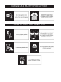
WHAT TO DO IF YOU SMELL GAS
WARNINGS & SAFETY PRECAUTIONS

WARNING
• Do not burn wood or other materials in this fireplace.
• Adults and especially children should be alerted to the hazards of high surface temperatures and should stay
away to avoid burns or clothing ignition. Keep young children and animals away when the fireplace is hot.
• Due to high temperatures, the fireplace should be located out of traffic and away from furniture and draperies.
• Clothing or other flammable material should not be placed on or near the fireplace.
• Any safety screen or guard removed for servicing must be replaced prior to operating the fireplace.
• It is imperative that the control compartments, burners and circulating blower and its passageway in the
fireplace and venting system are kept clean. The fireplace and its venting system should be inspected before
use and at least annually by a qualified service person. More frequent cleaning may be required due to excessive
lint from carpeting, bedding material, etc. The fireplace area must be kept clear and free from combustible
materials, gasoline and other flammable vapours and liquids.
• Under no circumstances should this fireplace be modified.
• This fireplace must not be connected to a chimney flue pipe serving a separate solid fuel burning appliance.
• Do not use this fireplace if any part has been under water. Immediately call a qualified service technician to
inspect the fireplace and to replace any part of the control system and any gas control which has been under
water.
• Do not operate the fireplace with the glass door removed, cracked or broken. Replacement of the glass should
be done by a licensed or qualified service person. Use only with a glass door certified with the fireplace.
• Do not strike or slam shut the fireplace glass door.
• This fireplace uses and requires a fast acting thermocouple. Replace only with a fast acting thermocouple
supplied by Wolf Steel Ltd.
19-20 FINISHING
Door Removal & Installation
Louvre Installation
Log Placement / Glowing Embers
Charcoal Embers
Charcoal Lumps
Logo Placement
21
OPTIONAL BLOWER INSTALLATION
22 OPTIONAL FAN INSTALLATION /
GD36 THERMOSTATIC SENSOR
CONTROL
23 OPERATION / MAINTENANCE
Operating Instructions
Maintenance
24 ADJUSTMENTS
Pilot Burner Adjustment
Venturi Adjustment
25-26 REPLACEMENTS
Ordering Replacement Parts
Replacement Parts
Vent Kits
Terminal Kits
Accessories
27-28 TROUBLE SHOOTING GUIDE
PG 2-5 INTRODUCTION
Warnings and Safety Precautions
Warranty
General Instructions
General Information
Care of Glass & Plated Parts
6 - 13 VENTING
Venting Lengths
Air Terminal Locations
Typical Vent Installations
Special Vent Installations
Venting Specifications
14
-
18 INSTALLATION
Wall and Ceiling Protection
Using Flexible Vent Components
Fireplace Vent Connection
Restricting Vertical Vents
Gas Installation
Mobile Home Installation
Framing
Nailing Tab Installation
Mantle Installation
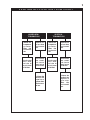
NOTE: changes, other than editorial, are denoted by a vertical line in the margin.
TABLE of CONTENTS
PLEASE RETAIN THIS MANUAL FOR FUTURE REFERENCE

4
W415-0484 / A / 07.26.06
ALL SPECIFICATIONS AND DESIGNS ARE SUBJECT TO CHANGE WITHOUT PRIOR NOTICE DUE TO ON-GOING PRODUCT IMPROVEMENTS. NAPOLEON® IS A REGISTERED
TRADEMARK OF WOLF STEEL LTD. PATENTS U.S. 5.303.693.801 - CAN. 2.073.411, 2.082.915. © WOLF STEEL LTD.
NAPOLEON NAPOLEON
NAPOLEON NAPOLEON
NAPOLEON
gas fireplaces are manufactured under the strict Standard of the world recog-gas fireplaces are manufactured under the strict Standard of the world recog-
gas fireplaces are manufactured under the strict Standard of the world recog-gas fireplaces are manufactured under the strict Standard of the world recog-
gas fireplaces are manufactured under the strict Standard of the world recog-
nized nized
nized nized
nized
ISO 9001 : 2000 Quality Assurance Certificate.ISO 9001 : 2000 Quality Assurance Certificate.
ISO 9001 : 2000 Quality Assurance Certificate.ISO 9001 : 2000 Quality Assurance Certificate.
ISO 9001 : 2000 Quality Assurance Certificate.
NAPOLEONNAPOLEON
NAPOLEONNAPOLEON
NAPOLEON
products are designed with superior components and materials, assembled by products are designed with superior components and materials, assembled by
products are designed with superior components and materials, assembled by products are designed with superior components and materials, assembled by
products are designed with superior components and materials, assembled by
trained craftsmen who take great pride in their work. The burner and valve assembly are leaktrained craftsmen who take great pride in their work. The burner and valve assembly are leak
trained craftsmen who take great pride in their work. The burner and valve assembly are leaktrained craftsmen who take great pride in their work. The burner and valve assembly are leak
trained craftsmen who take great pride in their work. The burner and valve assembly are leak
and test-fired at a quality test station. Once assembled the complete fireplace is thoroughlyand test-fired at a quality test station. Once assembled the complete fireplace is thoroughly
and test-fired at a quality test station. Once assembled the complete fireplace is thoroughlyand test-fired at a quality test station. Once assembled the complete fireplace is thoroughly
and test-fired at a quality test station. Once assembled the complete fireplace is thoroughly
inspected by a qualified technician before packaging to ensure that you, the customerinspected by a qualified technician before packaging to ensure that you, the customer
inspected by a qualified technician before packaging to ensure that you, the customerinspected by a qualified technician before packaging to ensure that you, the customer
inspected by a qualified technician before packaging to ensure that you, the customer
, receives the, receives the
, receives the, receives the
, receives the
quality product that you expect from quality product that you expect from
quality product that you expect from quality product that you expect from
quality product that you expect from
NAPOLEONNAPOLEON
NAPOLEONNAPOLEON
NAPOLEON
..
..
.
NAPOLEON GAS FIREPLACE PRESIDENT'S LIFETIME LIMITED WARRANTYNAPOLEON GAS FIREPLACE PRESIDENT'S LIFETIME LIMITED WARRANTY
NAPOLEON GAS FIREPLACE PRESIDENT'S LIFETIME LIMITED WARRANTYNAPOLEON GAS FIREPLACE PRESIDENT'S LIFETIME LIMITED WARRANTY
NAPOLEON GAS FIREPLACE PRESIDENT'S LIFETIME LIMITED WARRANTY
The following materials and workmanship in your new The following materials and workmanship in your new
The following materials and workmanship in your new The following materials and workmanship in your new
The following materials and workmanship in your new
NAPOLEONNAPOLEON
NAPOLEONNAPOLEON
NAPOLEON
gas fireplace are warranted against defects for as gas fireplace are warranted against defects for as
gas fireplace are warranted against defects for as gas fireplace are warranted against defects for as
gas fireplace are warranted against defects for as
long as you own the fireplace. This covers: combustion chamberlong as you own the fireplace. This covers: combustion chamber
long as you own the fireplace. This covers: combustion chamberlong as you own the fireplace. This covers: combustion chamber
long as you own the fireplace. This covers: combustion chamber
, heat e, heat e
, heat e, heat e
, heat e
xchangerxchanger
xchangerxchanger
xchanger
, stainless steel burner, stainless steel burner
, stainless steel burner, stainless steel burner
, stainless steel burner
, phazer™ logs and, phazer™ logs and
, phazer™ logs and, phazer™ logs and
, phazer™ logs and
embers, ceramic glass (thermal breakage only), gold plated parts against tarnishing, porcelainized enamelled componentsembers, ceramic glass (thermal breakage only), gold plated parts against tarnishing, porcelainized enamelled components
embers, ceramic glass (thermal breakage only), gold plated parts against tarnishing, porcelainized enamelled componentsembers, ceramic glass (thermal breakage only), gold plated parts against tarnishing, porcelainized enamelled components
embers, ceramic glass (thermal breakage only), gold plated parts against tarnishing, porcelainized enamelled components
and aluminum extrusion trims.and aluminum extrusion trims.
and aluminum extrusion trims.and aluminum extrusion trims.
and aluminum extrusion trims.
Electrical (110V and millivolt) components and wearable parts such as blowers, gas valves, thermal switch, switches,Electrical (110V and millivolt) components and wearable parts such as blowers, gas valves, thermal switch, switches,
Electrical (110V and millivolt) components and wearable parts such as blowers, gas valves, thermal switch, switches,Electrical (110V and millivolt) components and wearable parts such as blowers, gas valves, thermal switch, switches,
Electrical (110V and millivolt) components and wearable parts such as blowers, gas valves, thermal switch, switches,
wiring, remote controls, ignitorwiring, remote controls, ignitor
wiring, remote controls, ignitorwiring, remote controls, ignitor
wiring, remote controls, ignitor
, gask, gask
, gask, gask
, gask
eting, and pilot assembly are covered and eting, and pilot assembly are covered and
eting, and pilot assembly are covered and eting, and pilot assembly are covered and
eting, and pilot assembly are covered and
NAPOLEONNAPOLEON
NAPOLEONNAPOLEON
NAPOLEON
will provide replacement partswill provide replacement parts
will provide replacement partswill provide replacement parts
will provide replacement parts
free of charge during the first year of the limited warfree of charge during the first year of the limited war
free of charge during the first year of the limited warfree of charge during the first year of the limited war
free of charge during the first year of the limited war
rantyranty
rantyranty
ranty
..
..
.
L
L
LL
L
abour related to warabour related to war
abour related to warabour related to war
abour related to war
ranty repair is covered free of charge during the first yearranty repair is covered free of charge during the first year
ranty repair is covered free of charge during the first yearranty repair is covered free of charge during the first year
ranty repair is covered free of charge during the first year
. R. R
. R. R
. R
epair work, howeverepair work, however
epair work, howeverepair work, however
epair work, however
, requires the prior, requires the prior
, requires the prior, requires the prior
, requires the prior
approval of an authorized company official. Labour costs to the account of approval of an authorized company official. Labour costs to the account of
approval of an authorized company official. Labour costs to the account of approval of an authorized company official. Labour costs to the account of
approval of an authorized company official. Labour costs to the account of
NAPOLEONNAPOLEON
NAPOLEONNAPOLEON
NAPOLEON
are based on a predetermined rate are based on a predetermined rate
are based on a predetermined rate are based on a predetermined rate
are based on a predetermined rate
schedule and any repair work must be done through an authorized schedule and any repair work must be done through an authorized
schedule and any repair work must be done through an authorized schedule and any repair work must be done through an authorized
schedule and any repair work must be done through an authorized
NAPOLEONNAPOLEON
NAPOLEONNAPOLEON
NAPOLEON
dealer dealer
dealer dealer
dealer
..
..
.
CONDITIONS AND LIMITATIONS
NAPOLEON warrants its products against manufacturing defects to the original purchaser only -- i.e., the individual or legal entity (registered
customer) whose name appears on the warranty registration card filed with NAPOLEON -- provided that the purchase was made through an authorized
NAPOLEON dealer and is subject to the following conditions and limitations:
This factory warranty is nontransferable and may not be extended whatsoever by any of our representatives.
The gas fireplace must be installed by a licenced, authorized service technician or contractor. Installation must be done in accordance with the
installation instructions included with the product and all local and national building and fire codes.
This limited warranty does not cover damages caused by misuse, lack of maintenance, accident, alterations, abuse or neglect and parts installed
from other manufacturers will nullify this warranty.
This limited warranty further does not cover any scratches, dents, corrosion or discolouring caused by excessive heat, abrasive and chemical
cleaners nor chipping on porcelain enamel parts, mechanical breakage of PHAZER™ logs and embers, nor any venting components used in the
installation of the fireplace.
NAPOLEON warrants its stainless steel burners against defects in workmanship and material for life, subject to the following conditions: During the
first 10 years NAPOLEON will replace or repair the defective parts at our option free of charge. From 10 years to life, NAPOLEON will provide
replacement burners at 50% of the current retail price.
In the first year only, this warranty extends to the repair or replacement of warranted parts which are defective in material or workmanship provided
that the product has been operated in accordance with the operation instructions and under normal conditions.
After the first year, with respect to this President's Limited Lifetime Warranty, NAPOLEON may, at its discretion, fully discharge all obligations with
respect to this warranty by refunding to the original warranted purchaser the wholesale price of any warranted but defective part(s).
After the first year, NAPOLEON will not be responsible for installation, labour or any other costs or expenses related to the reinstallation of a
warranted part, and such expenses are not covered by this warranty.
Notwithstanding any provisions contained in this President's Limited Lifetime Warranty, NAPOLEON’S responsibility under this warranty is defined
as above and it shall not in any event extend to any incidental, consequential or indirect damages.
This warranty defines the obligations and liability of NAPOLEON with respect to the NAPOLEON gas fireplace and any other warranties expressed
or implied with respect to this product, its components or accessories are excluded.
NAPOLEON neither assumes, nor authorizes any third party to assume, on its behalf, any other liabilities with respect to the sale of this product.
NAPOLEON will not be responsible for: over-firing, downdrafts, spillage caused by environmental conditions such as rooftops, buildings, nearby
trees, hills, mountains, inadequate vents or ventilation, excessive venting configurations, insufficient makeup air, or negative air pressures which
may or may not be caused by mechanical systems such as exhaust fans, furnaces, clothes dryers, etc.
Any damages to fireplace, combustion chamber, heat exchanger, brass trim or other component due to water, weather damage, long periods of
dampness, condensation, damaging chemicals or cleaners will not be the responsibility of NAPOLEON.
The bill of sale or copy will be required together with a serial number and a model number when making any warranty claims from your authorized
dealer. The warranty registration card must be returned within fourteen days to register the warranty.
NAPOLEON reserves the right to have its representative inspect any product or part thereof prior to honouring any warranty claim.

5
W415-0484 / A / 07.23.06
THIS GAS FIREPLACE SHOULD BE INSTALLED AND SERV-
ICED BY A QUALIFIED INSTALLER to conform with local
codes. In absence of local codes, install the B36DF to the current
National Fuel Gas Code, ANSI Z223.1, or the current
CAN/CGA B149, Installation Codes.
Installation practices vary from region to region and it is
important to know the specifics that apply to your area,
for example: in Massachusetts State:
• The fireplace damper must be removed or welded in the open
position prior to installation of a fireplace insert or gas log.
• A carbon monoxide detector is required in all rooms containing
gas fired appliances
• The appliance off valve must be a “T” handle gas cock.
• The flexible connector must not be longer than 36 inches.
• The appliance is not approved for installation in a bedroom or
bathroom unless the unit is a direct vent sealed combustion
product.
• WARNING: This product must be installed by a licensed plumber
or gas fitter when installed within the commonwealth of
Massachusetts.
Mobile home installation must conform with local codes or in the
absence of local codes, install to the current standard for gas
equipped mobile housing CAN/CSA ZA240 MH Series in Canada
or the Manufactured Home Construction and Safety Standard,
Title 24 CFR, Part 3280, or the Fire Safety Criteria for Manufac-
tured Home Installations, Sites and Communities Standard ANSI/
NFPA 501A in the United States.
The fireplace and its individual shutoff valve must be discon-
nected from the gas supply piping system during any pressure
testing of that system at test pressures in excess of 1/2 psig
(3.5 kPa). The fireplace must be isolated from the gas supply
piping system by closing its individual manual shutoff valve
during any pressure testing of the gas supply piping system at
test pressures equal to or less than 1/2 psig (3.5 kPa).
When the fireplace is installed directly on carpeting, vinyl tile
or other combustible material other than wood flooring, the
fireplace shall be installed on a metal or wood panel extend-
ing the full width and depth.
If the optional fan or blower is installed, the junction box must
be electrically connected and grounded in accordance with
local codes. In the absence of local codes, use the current
CSA C22.1 CANADIAN ELECTRICAL CODE in Canada or the
ANSI/NFPA 70 NATIONAL ELECTRICAL CODE in the United
States.
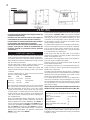
FOR YOUR SATISFACTION, THIS FIREPLACE HAS BEEN
TEST-FIRED TO ASSURE ITS OPERATION AND QUALITY!
Maximum input is 23,000 BTU/hr for natural gas and propane.
When the fireplace is installed at elevations above 4,500ft, and
in the absence of specific recommendations from the local au-
thority having jurisdiction, the certified high altitude input rating
shall be reduced at the rate of 4% for each additional 1,000ft.
Maximum output for natural gas and propane is 15,200 BTU/
hr at an efficiency of 66% with the fan on. The maximum A.F.U.E.
(annual fuel utilization efficiency) rating is 62% for natural gas
and propane.
Minimum inlet gas supply pressure is 4.5 inches water col-
umn for natural gas and 11 inches water column for propane.
Maximum inlet gas pressure is 7 inches water column for
natural gas and 13 inches water column for propane. Mani-
fold pressure under flow conditions is 3.5 inches water col-
umn for natural gas and 10 inches water column for propane.
This fireplace is approved for bathroom, bedroom and bed-
sitting room installations and is suitable for mobile home
installation.
No external electricity (110 volts or 24 volts) is required
for the gas system operation.
Expansion / contraction noises during heating up and cool-
ing down cycles are normal and are to be expected.
Do not use abrasive cleaners to clean plated parts. Buff lightly
with a clean dry cloth. The B36DF is factory equipped with
tempered glass. The glass thickness is 3/16". Use only re-
placement glass available from your Napoleon dealer. DO
NOT SUBSTITUTE MATERIALS. Clean the glass after the first
10 hours of operation with a recommended gas fireplace
glass cleaner. Thereafter clean as required. DO NOT CLEAN
GLASS WHEN HOT! If the glass is not kept clean permanent
discolouration and / or blemishes may result.
Use only accessories designed for and listed with
your specific fireplace.
Provide adequate ventilation air. Provide adequate ac-
cessibility clearance for servicing and operating the
fireplace. Never obstruct the front opening of the fire-
place.
For safe and proper operation of the fireplace follow the
venting instruction exactly.
In order to avoid the possibility of exposed insulation or
vapour barrier coming in contact with the fireplace body,
it is recommended that the walls of the fireplace enclo-
sure be 'finished', (i.e. drywall/sheetrock) as would any
other outside wall of the home. This will ensure that
clearance to combustibles is maintained within the cav-
ity.
GENERAL INSTRUCTIONS
GENERAL INFORMATION
CARE OF GLASS, AND PLATED PARTS

6
W415-0484 / A / 07.26.06
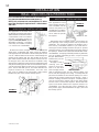
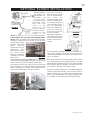
Use only Wolf Steel, Simpson Dura-Vent, Selkirk Direct
Temp or American Metal Amerivent venting components.
For Simpson Dura-Vent, Selkirk Direct Temp and American
Metal Amerivent, follow the installation procedure provided
with the venting components.
All outer pipe joints of these venting systems must be
sealed using Red RTV Hight Temperature Sealant.
Wolf Steel, Simpson Dura-Vent, Selkirk Direct Temp and
American Metal Amerivent venting systems must not be
combined.
A starter adaptor must be used and may be purchased
from the corresponding supplier:
PART 5"/8" SUPPLIER
Duravent W175-0170 Wolf Steel
Amerivent 5DSC-N American Metal
Direct Temp 5DT-AAN Selkirk
For vent systems that provide seals on the inner exhaust
flue, only the outer air intake joints must be sealed using a
red high temperature silicone (RTV). This same sealant
maybe used on both the inner exhaust and outer intake
vent pipe joints of all other approved vent systems except
for the exhaust vent pipe connection to the fireplace flue
collar which must be sealed using the black high tempera-
ture sealant Mill Pac.
When using Wolf Steel venting components, use only ap-
proved Wolf Steel rigid / flexible components with the fol-
lowing termination kits: WALL TERMINAL KIT GD422, or
1/12 TO 7/12 PITCH ROOF TERMINAL KIT GD410, 8/12 TO
12/12 ROOF TERMINAL KIT GD411, FLAT ROOF TERMI-
NAL KIT GD412 or PERISCOPE KIT GD401 (for wall pen-
etration below grade). With flexible venting, in conjunction
with the various terminations, use either the 5 foot vent kit
GD420 or the 10 foot vent kit GD430.
These vent kits allow for either horizontal or vertical venting
of the fireplace. FIGURES 3 & 5. The maximum allowable
horizontal run is 20 feet. The maximum allowable vertical
vent length is 40 feet. The maximum number of 5" vent
connections is two horizontally or three vertically (exclud-
ing the fireplace and the air terminal connections) when
using aluminum flexible venting.
For optimum flame appearance and fireplace performance,
keep the vent length and number of elbows to a minimum.
The air terminal must remain unobstructed at all times.
Examine the air terminal at least once a year to verify that
it is unobstructed and undamaged.
Purge all gas lines with the glass door of the fireplace
removed. Assure that a continuous gas flow is at the burner
before re-installing the door.
Under extreme vent configurations, allow several minutes (5-
15) for the flame to stabilize after ignition.
Eight (8") inches is the minimum bend radius allowed for
the 8" diameter flexible liner.
For optimum performance it is recommended that all hori-
zontal runs have a 1 inch rise per foot when using Napoleon
flexible vent components.
A terminal shall not terminate directly above a sidewalk or
paved driveway which is located between two single family
dwellings and serves both dwellings. Local codes or regu-
lations may require different clearances.
Do not allow the inside liner to bunch up on horizontal or
vertical runs and elbows. Keep it pulled tight. A 1¼" air gap
all around between the inner liner and outer liner is required
for safe operation. Use a firestop when penetrating interior
walls, floor or ceiling.
Objects placed in front of the fireplace must be kept a
minimum of 48" away from the front face of the unit.
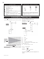
FIGURE 1
Horizontal runs may have a 0 inch rise per foot in all cases
using SIMPSON DURA-VENT or NAPOLEON RIGID OR
FLEXIBLE venting components when venting as illustrated
in Figures 3, and 4.
VENTING
VENTING LENGTHS
Minimum clearance to combustible con-
struction from fireplace and vent sur-
faces:
sides, back and bottom 0" (to stand off)
top (framing) 8"
finishing 0"
recessed depth 21"
sides and bottom of the vent pipe 1"
top of vent 2"
For safe and proper operation of the fireplace follow the
venting instruction exactly.
Deviation from the minimum vertical vent length can
create difficulty in burner start-up and/or carboning.
Provide a means for visually checking the vent connection
to the fireplace after the fireplace is installed.
Vent lengths that pass through unheated spaces (attics,
garages, crawl spaces) should be insulated with the
insulation wrapped in a protective sleeve to minimize
condensation.

7
W415-0484 / A / 07.23.06
**
**
* Recommended to prevent condensation on windows and thermal breakage
****
****
** It is recommended to use a heat shield and to maximize the distance to vinyl clad soffits.
******
******
*** The periscope GD-201 requires a minimum 18 inches clearance from an inside corner.
********
********
**** This is a recommended distance. For additional requirements check local codes.
††
††
† Three feet above if within 10 feet horizontally.
‡‡
‡‡
‡ A vent shall not terminate directly above a sidewalk or paved driveway that is located between two single family
dwellings and serves both dwellings.
††††
††††
†† Permitted only if the veranda, porch, or deck is fully open on a minimum of two sides beneath the floor.
†*†*
†*†*
†* Recommenced to prevent recirculation of exhaust products. For additional requirements check local codes.
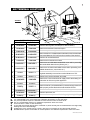
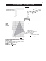
A
B
C
D
E
F
G
H
I
J
K
L
M
N
O
12 INCHES
9 INCHES
12 INCHES*
18 INCHES**
12 INCHES**
0 INCHES
0 INCHES***
2 INCHES***
3 FEET****
3 FEET****
9 INCHES
3 FEET†
7 FEET****
12 INCHES****
16 INCHES
2 FEET†*
Clearance above grade, veranda porch, deck or balcony.
Clearance to windows or doors that open.
Clearance to permanently closed windows.
Vertical clearance to ventilated soffit located above the terminal within
a horizontal distance of 2 feet from the centerline of the terminal.
Clearance to unventilated soffit.
Clearance to an outside corner wall.
Clearance to an inside non-combustible corner wall or protruding
non-combustible obstructions (chimney, etc.).
Clearance to an inside combustible corner wall or protruding com-
bustible obstructions ( vent chase, etc.).
Clearance to each side of the centerline extended above the meter
/ regulator assembly to a maximum vertical distance of 15ft.
Clearance to a service regulator vent outlet.
Clearance to a non-mechanical air supply inlet to the building or a
combustion air inlet to any other appliance.
Clearance to a mechanical air supply inlet.
Clearance above a paved sidewalk or paved driveway located on
public property unless fitted with a heat shield kit GD-301.
Clearance under a veranda, porch, deck or balcony.
Clearance above the roof.
Clearance from an adjacent wall including neighbouring buildings.
CANADIAN U.S.A.
12 INCHES
12 INCHES
12 INCHES*
18 INCHES**
12 INCHES**
0 INCHES
0 INCHES***
2 INCHES***
3 FEET
3 FEET
12 INCHES
6 FEET
7 FEET‡
12 INCHES††
16 INCHES
2 FEET†*
INSTALLATIONS
AIR TERMINAL LOCATIONS
FIGURE 2

8
W415-0484 / A / 07.26.06
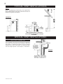
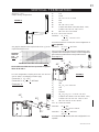
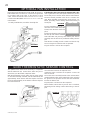
Use the GD401 periscope kit to locate the air termination
above grade. The periscope must be installed so that when
final grading is completed, the bottom air slot is located a
minimum of 12 inches above grade. The maximum allow-
able vent length depends on the fireplace, as illustrated.
FIGURES 3 a-c
FIGURE 4
TYPICAL VENT INSTALLATIONS
SPECIAL VENT INSTALLATIONS
NOTE:
When terminating vertically, the restrictor
plate W500-0205 must be installed. Refer to
Restricting Vertical Vents.
PERISCOPE TERMINATION
* When installing with no vertical rise,
ensure that the vent pipe does not slope
downward.

9
W415-0484 / A / 07.23.06
VERTICAL
TERMINATION
HORIZONTAL
TERMINATION
Vertical rise
is equal to or
greater
than the
horizontal
run
Horizontal
run + verti-
cal rise to
maximum
of 40 feet
Vertical rise
is equal to or
greater
than the
horizontal
run
Horizontal
run + verti-
cal rise to
maximum
of 40 feet
Vertical rise
is less than
horizontal
run
Horizontal
run + verti-
cal rise to
maximum
of 24.75 feet
4.2 times the
vertical rise
equal to or
greater than
the horizon-
tal run
Vertical rise
is less than
horizontal
run
Horizontal
run + verti-
cal rise to
maximum
of 40 feet
3 times the
vertical rise
equal to or
greater
than the
horizontal
run
VENTING APPLICATION FLOW CHART

10
W415-0484 / A / 07.26.06
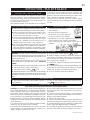
ELBOW VENT LENGTH VALUES
DEFINITIONS
HORIZONTAL TERMINATION
REQUIRED
VERTICAL
RISE IN
FEET
(V
T
)
CALCULATED HORIZONTAL VENT RUN
PLUS OFFSETS IN FEET (H
T
)
FIGURE 5
45º
FIGURE 6
90°
H
1
H
2
when (H
T
) < (V
T
)
Simple venting configuration (only one 45º and 90° elbow)
for the following symbols used in the venting calcula-
tions and examples are:
> - greater than
> - equal to or greater than
< - less than
< - equal to or less than
H
T
- total of both horizontal vent lengths (H
R
) and off-
sets (H
O
) in feet
H
R
- combined horizontal vent lengths in feet
H
O
- offset factor: .03(total degrees of offset - 135°
**
**
*) in
feet
V
T
- combined vertical vent lengths in feet
feet inches
1° 0.03 0.5
15° 0.45 6.0
30° 0.9 11.0
45°
**
**
* 1.35 16.0
90°
**
**
* 2.7 32.0
* *
* *
* the first 45º and 90° offset has a zero value and is
shown in the formula as -45° and -90º respectively
or -135º when combined.
For vent configurations requiring more than one 45º and
90° elbow, the following formulas apply:
Formula 1: H
T
< V
T
Formula 2: H
T
+ V
T
< 40 feet
Example 1:
V
1
=8 ft
V
T
=
V
1
= 8 ft
H
1
= 2.5 ft
H
2
=2 ft
H
R
= H
1
+ H
2
= 2.5 + 2 = 4.5 ft
H
O
=.
03(one 45º elbow + two 90º elbows - 135º)
=0.3(225-135º) = 2.7ft
H
T
= H
R
+ H
O
= 4.5 + 2.7 = 7.2 ft
H
T
+ V
T
= 7.2 +8 =15.2ft
Formula 1: H
T
< V
T
7.2 < 8
Formula 2: H
T
+ V
T
< 40 feet
15.2 < 40
45º
90°
Since both formulas are met, this vent configuration is ac-
ceptable.
V
1
90°
The shaded area within the lines represents acceptable
values for H
T
and V
T
.

11
W415-0484 / A / 07.23.06
V
1
HORIZONTAL TERMINATION
See graph to determine the re-
quired vertical rise V
T
for the re-
quired horizontal run H
T
.
For vent configurations requiring more than one 45º and
90° elbow the following formulas apply:
Formula 1: H
T
< 4.2 V
T
Formula 2: H
T
+ V
T
< 24.75 feet
FIGURE 7
REQUIRED
VERTICAL
RISE IN
INCHES (V
T
)
HORIZONTAL VENT RUN PLUS OFFSETS IN FEET (HT)
when (H
T
) > (V
T
)
Simple venting configuration (only one 45º and 90° elbow)
Example 2:
V
1
=4 ft
V
2
= 1.5 ft
V
T
= V
1
+
V
2
= 4 ft + 1.5 ft = 5.5 ft
H
1
=2 ft
H
2
=1 ft
H
3
=1 ft
H
4
= 1.5 ft
H
R
= H
1
+ H
2
+ H
3
+ H
4
= 2 + 1 + 1 + 1. 5 = 5.5 ft
H
O
= .03(one 45º elbow + three 90º elbow -135º)
=.03(315-135)=5.4ft
H
T
= H
R
+ H
O
= 5.5 +5.4 = 10.9 ft
H
T
+ V
T
= 10.9 + 5.5 = 16.4 ft
Formula 1:H
T
< 4.2 V
T
4.2 V
T
= 4.2 x 5.5 = 23.1 ft
10.9 < 23.1
Formula 2:H
T
+ V
T
< 24.75 feet
16.4 < 24.75
Since both formulas are met, this vent configuration is ac-
ceptable.
H
4
90°
H
3
H
1
90°
H
2
90°
FIGURE 8
45°
The shaded area within the lines represents acceptable
values for H
T
and V
T
.
V
2

12
W415-0484 / A / 07.26.06
VERTICAL TERMINATION
Example 3:
V
1
=5 ft
V
2
=10 ft
V
T
=
V
1
+
V
2
=
5 + 10 = 15 ft
H
1
=3 ft
H
2
=2.5 ft
H
R
=H
1
+ H
2
= 3 + 2.5 = 5.5 ft
H
O
=.03(one 45º elbow + three 90º elbows - 135º)
=.03(45+90+90+90-135)=5.4
H
T
=H
R
+ H
O
= 5.5 + 5.4 = 10.9 ft
H
T
+ V
T
= 10.9 + 15 = 25.9 ft
Formula 1: H
T
< V
T
10.9 < 15
Formula 2: H
T
+ V
T
< 40 feet
25.9 < 40
Since both formulas are met, this vent configuration is ac-
ceptable.
when (H
T
) < (V
T
)
Simple venting configurations
FIGURE 9
REQUIRED VERTICAL RISE IN
FEET (V
T
)
HORIZONTAL VENT RUN
PLUS OFFSETS IN FEET (H
T
)
FIGURE10
For vent configurations requiring more than one 45º and
one 90° elbow , the following formulas apply:
Formula 1: H
T
< V
T
Formula 2: H
T
+ V
T
< 40 feet
See graph to determine the required vertical rise V
T
for the
required horizontal run H
T
.
90°
90°
V
1
H
1
H
2
V
2
45°
45°
90°
The shaded area within the lines represents acceptable
values for H
T
and V
T
.

13
W415-0484 / A / 07.23.06
H
1
VERTICAL TERMINATION
For vent configurations requiring more than one 45º and
one 90° elbow , the following formulas apply:
Formula 1: H
T
< 3V
T
Formula 2: H
T
+ V
T
< 40 feet
Example 4:
when (H
T
) > (V
T
)
Simple venting configurations
See graph to determine the required vertical rise V
T
for the
required horizontal run H
T
.
V
1
=1 ft
V
2
= 1.5 ft
V
T
=
V
1
+
V
2
=
1 + 1.5 = 2.5 ft
H
1
=6 ft
H
2
=2 ft
H
R
=H
1
+ H
2
= 6 + 2 = 8 ft
H
O
=.03(one 45º elbow + three 90º elbow - 135º)
=.03(45 + 90 + 90 + 90 - 135) = 5.4 ft
H
T
=H
R
+ H
O
= 8 + 5.4 = 13.4 ft
H
T
+ V
T
= 13.4 + 2.5 = 15.9 ft
Formula 1: H
T
< 3V
T
3V
T
=
3 x
2.5 = 7.5 ft
13.4 > 7.5
Since this formula is not met, this vent configuration is
unacceptable.
Formula 2: H
T
+ V
T
< 40 feet
15.9 < 40
Since only formula 2 is met, this vent configuration is unac-
ceptable and a new fireplace location or vent configuration
will need to be established to satisfy both formulas.
Example 5:
V
1
=1.5 ft
V
2
=8 ft
V
T
=
V
1
+
V
2
=
1.5 + 8= 9.5 ft
H
1
=1 ft
H
2
=1 ft
H
3
=10.75 ft
H
R
=H
1
+ H
2
+ H
3
= 1 + 1 + 10.75 = 12.75 ft
H
O
=.03(three 90° elbows + two 45° elbow - 135°)
=.03(90 + 90 + 90 + 45 + 45 - 135) = 6.75 ft
H
T
=H
R
+ H
O
= 12.75 + 6.75 = 19.5 ft
H
T
+ V
T
= 19.5 + 9.5= 29 ft
Formula 1: H
T
< 3V
T
3V
T
=
3 x
9.5 = 28.5 ft
19.5 < 28.5
Formula 2: H
T
+ V
T
< 40 feet
29 < 40
Since both formulas are met, this vent configuration is ac-
ceptable.
REQUIRED
VERTICAL
RISE IN
FEET (V
T
)
HORIZONTAL VENT RUN PLUS OFFSET IN FEET (H
T
)
FIGURE 13
FIGURE 11
45°
45°
90°
90°
H
1
90°
H
3
The shaded area within the lines represents acceptable
values for H
T
and V
T
.
90°
FIGURE 12
45°
V
1
90°
V
2
90°
H
2
V
2
V
1
H
2

14
W415-0484 / A / 07.26.06
This application occurs
when venting through a
roof. Installation kits for
various roof pitches are
available from your Napo-
leon dealer. See Accesso-
ries to order the specific
kit required.
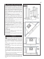
1. Determine the air terminal location, cut and frame 10
inch openings in the ceiling and the roof to provide the
minimum 1 inch clearance between the fireplace pipe /
liner and any combustible material. Try to center the ex-
haust pipe location midway between two joist to prevent
having to cut them. Use a plumb bob to line up the center of
the openings. DO NOT FILL THIS SPACE WITH ANY TYPE
OF MATERIAL. A vent pipe shield will prevent any materials
such as insulation, from filling up the 1" air space around
the pipe. Nail headers
between the joist for
extra support.
2. Apply a bead of
caulking (not sup-
plied) to the frame-
work or to the Wolf
Steel vent pipe shield
plate or equivalent (in the case of a finished ceiling), and
secure over the opening in the ceiling. A firestop must be
placed on the bottom of each framed opening in a roof or
ceiling that the venting system passes through. Apply a
bead of caulking all around and place a firestop spacer
over the vent shield to restrict cold air from being drawn
into the room or around the fireplace. Ensure that both
spacer and shield maintain the required clearance to
combustibles. Once the vent pipe / liner is installed in its
final position, apply sealant between the pipe / liner and
the firestop spacer.
FIGURE 16
This application occurs when vent
ing through an exterior wall. Having
determined the air terminal location,
cut and frame a hole in an exterior
wall with a minimum opening as
required. See Note above. (As an
alternative to framing, a vent pipe
shield may be installed, ensuring
a 1" clearance to combustibles.
1. Mark and cut the vent pipe shield to the determined
depth of the combustible wall. Apply a bead of caulking
(not supplied) to the framework or to the shield plate (in the
case of a finished wall) and secure the shield through the
opening to the interior wall. The final location of the vent
pipe shield should maintain the required clearance to the
8" vent pipe / liner. (See note above). Do not fill this cavity
with any type of material. Apply a bead of caulking all around
and place a firestop spacer over the vent shield to restrict
cold air from being drawn into the room or around the fire-
place. Ensure that both spacer and shield maintain the
required clearance to combustibles. Once the vent
pipe / liner is installed in its final position, apply sealant
between the pipe / liner and the firestop spacer.
FIGURE 15
FIGURE 14
OR
FOR SAFE AND PROPER OPERATION OF THE FIREPLACE,
FOLLOW THE VENTING INSTRUCTIONS EXACTLY.
NOTE: Only a clearance to combustibles of 2" at the
top of the vent pipe is required and 1" at the bottom
and sides.
HORIZONTAL INSTALLATION
VERTICAL INSTALLATION
INSTALLATION
WALL AND CEILING PROTECTION
FIGURE 17

15
W415-0484 / A / 07.23.06
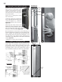
INNER FLEX
LINER
OUTER
FLEX
LINER
INNER
SLEEVE
HIGH
TEMPERATURE
SEALANT
AIR
TERMINAL
CONNECTOR
FIGURE 18
A VENT SHIELD MUST BE USED IF THE WALL TERMINAL IS
INSTALLED ON COMBUSTIBLE, EXTERIOR SURFACES.
1. Cut or frame a hole in an exterior wall with a minimum
oval or rectangle opening of 10½"w x 11 ½"h. Secure the
firestop spacer over the opening to the interior wall, ensur-
ing 2" clearance above the vent pipe opening.
2. Stretch the 5" diameter aluminum flexible liner to the
required length taking into account the additional length
needed for the finished wall surface. Slip the liner a mini-
mum of 2" over the inner sleeve of the air terminal and
secure with 3 #8 screws. Apply a heavy bead of the high
temperature sealant.
3. Using the 8" diameter flexible aluminum liner, slide
over the outer combustion air sleeve of the air terminal and
secure with 3 #8 screws. Seal as before.
The air terminal mounting plate may be recessed into
the exterior wall or siding by 1½", the depth of the return
flange.
5. Apply a heavy bead of the high temperature sealant,
Mill Pac, to the inside of the 5" liner approximately 1" from
the end. Slip the liner a minimum of 2" over the fireplace
vent collar and secure with 3 #8 screws.
6. Using the 8" diameter flexible aluminium liner, apply
sealant, slide a minimum of 2" over the fireplace combus-
tion air collar and secure with 3 #8 screws.
7. If more liner needs to be used to reach the fireplace,
couple them together as illustrated. The vent system must
be supported approximately every 3 feet for both vertical
and horizontal runs. Use noncombustible strapping to
maintain the minimum 1" clearance to combustibles.
FIGURE 19
HORIZONTAL AIR TERMINAL INSTALLATION
VERTICAL AIR TERMINAL INSTALLATION
4. Insert the liners through the firestop maintaining the
required clearance to combustibles. Holding the air termi-
nal (lettering in an upright, readable position), secure to
the exterior wall and make weather tight by sealing with
caulking (not supplied).
Use only approved aluminum flexible liner kits marked:
"Wolf Steel Approved Venting" as
identified by the stamp only on the 8”
outer liner.
USING FLEXIBLE VENT COMPONENTS
For safe and proper operation of the fireplace, follow the vent-
ing instructions exactly.
All inner exhaust and outer intake vent pipe joints may be
sealed using either Red RTV high temp silicone sealant or
Black high temp Mill Pac with the exception of the fireplace
exhaust flue collar which must be sealed using Mill Pac
(not supplied).
1. Fasten the roof
support to the roof
using the screws
provided. The roof
support is optional.
In this case the
venting is to be
adequately
supported using
either an alternate
method suitable to
the authority having jurisdiction or the optional roof support.
2. Stretch the exhaust to
the required length. Slip
the liner a minimum of
2" over the inner sleeve
of the air terminal and
secure with 3 #8 screws.
Seal using a heavy bead
of the high temperature
sealant.
3. Repeat using air
intake vent pipe.
4. Thread the air
terminal pipe assembly
down through the roof.
The air terminal must be
located vertically and
plumb. Attach the air
terminal assembly to the
roof support, ensuring that a minimum 16" of air terminal
will penetrate the roof when fastened.
DO NOT CLAMP THE FLEXIBLE ALUMINIUM LINER.
ROOF SUPPORT
FIGURE 20
FIGURE 21

16
W415-0484 / A / 07.26.06
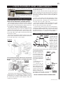
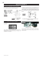
Vertical terminations may display a very active flame. As
this appearance is not desirable, the vent exit must be
restricted using restrictor plate, W500-0205. This reduces
the velocity of the exhaust gases, slowing down the flame
pattern and creating a more traditional appearance.
Remove the two screws on either side of the exhaust collar
inside the firebox. Install the plate as shown. The plate is
adjustable depending on the required restriction. Replace
the screws.
Proceed once the vent installation is complete.
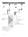
1. Move the fireplace into position and secure using the
nailing tabs and/or secure to the floor through the ¼"diam-
eter holes located at either end of the base.
2. Route a 3/8" N.P.T. black iron gas line, 1/2" type-L cop-
per tubing or equivalent to the fireplace.
3. For ease of accessibility, an optional remote wall switch
or millivolt thermostat may be installed in a convenient lo-
cation. Route 2-strand (solid core) millivolt wire through
the electrical hole located at the bottom left side of the unit.
The recommended maximum lead length depends on wire
size:
WIRE SIZE MAX. LENGTH
14 gauge 100 feet
16 gauge 60 feet
18 gauge 40 feet
Attach the two leads to terminals 1 and 3 located on the
gas valve.
4. Install rigid black pipe, 1/2" type-L copper tubing or, if
local codes permit, a 3/8" flex connector and shutoff valve
to the gas line and the fireplace gas valve.
Seal and tighten securely. An adapter fitting is required
between the gas valve and the copper tubing or flex con-
nector. Do not kink flex connector.
5. Check for gas leaks by brushing on a soap and water
solution. Do not use open flame.
Do not connect either the wall switch, thermostat or gas
valve to electricity (110 volts).
Purge all gas lines with the glass door of the fireplace
removed. Assure that a continuous gas flow is at the burner
before re-installing the door.
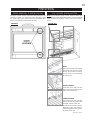
FIGURE 26
FIGURE 25
GAS INSTALLATION
RESTRICTING VERTICAL VENTS
FIGURE 23
FIREPLACE VENT CONNECTION
RESTRICTOR PLATE
TOP OF THE
FIREBOX
FLUE COLLAR
FIGURE 24
STORM
COLLAR
FLASHING
CAUL KI NG
W EAT HER
SEALANT
2”
AI R I NL ET
BASE
5. Remove nails from the shingles, above and to the sides
of the chimney. Place the flashing over the air terminal and
slide it underneath the sides and upper edge of the
shingles. Ensure that the air terminal is properly centred
within the flashing, giving a 3/4" margin all around. Fasten
to the roof. Do not nail through the lower portion of the
flashing. Make weather-tight by sealing with caulking.
Where possible, cover the sides and top edges of the
flashing with roofing material.
6. Apply a heavy bead of weatherproof caulking 2 inches
above the flashing. Slide the storm collar around the air
terminal and down to the
caulking. Tighten to ensure
that a weather-tight seal
between the air terminal
and the collar is achieved.
Attach the other storm
collar centred between the
air intake vent pipe and the
air exhaust slots onto the
air terminal. Tighten
securely. Attach the vertical
rain cap.
Spacers are attached to the exhaust liner at
predetermined intervals to maintain a 1-1/4" air gap to
the air intake vent pipe. These spacers must not be
removed.
1. Install the 5 inch diameter aluminium flexible liner to
the fireplace. Secure with 3 screws and flat washers. Seal
the joint and screw holes using the high temperature seal-
ant Mill Pac.
2. Install the 8 inch diameter aluminium flexible liner to
the fireplace. Attach and seal the joints.
FIGURE 22

17
W415-0484 / A / 07.23.06
This appliance may be installed as an OEM (Original
Equipment Manufacturer) installation in a manufactured
home or mobile home and must be installed in accordance
with the manufacturer’s instructions and the Manufactured
Home Construction and Safety Standard, Title 24 CFR, Part
3280, in the United States or the Mobile Home Standard,
CAN/CSA Z240 MH Series, in Canada. This appliance is
only for use with the type(s) of gas indicated on the rating
plate. A conversion kit is supplied with the mobile home
appliance.
This Mobile/Manufactured Home Listed appliance comes
factory equipped with a means to secure the unit.
The fireplace is equipped with two 1/4” diameter holes
located in the front left and right corners of the base. For
mobile home installations, the fireplace must be fastened
in place. Use #10 hex head screws, inserted through the
holes in the base to secure.
Always turn off the pilot and the fuel supply at the source,
prior to moving the mobile home.
After moving the mobile home and prior to lighting the
fireplace, ensure that the logs are positioned correctly.
This appliance may be installed in an aftermarket
permanently located, manufactured (mobile) home, where
not prohibited by local codes.
This appliance is only to be used with the type of gas
indicated on the rating plate. This appliance is not
convertible for use with other gases, unless a certified kit
is used.
Conversion Kits
The mobile home appliance is field convertible between
Natural Gas (NG) and Propane (LP).
To convert from Natural Gas to Propane order conversion
kit # W175-0235
To convert from Propane to Natural Gas order conversion
kit # W175-0236
Note: In order to avoid the possibility of exposed insulation
or vapour barrier coming in contact with the fireplace body,
it is recommended that the walls of the fireplace enclo-
sure be “finished” (ie: drywall/sheetrock), as you would
finish any other outside wall of a home. This will ensure
that clearance to combustibles is maintained within the
cavity.
It is best to frame your fireplace after it is positioned and
the vent system is installed. Use 2x4's and frame to local
building codes.
It is not necessary to install a hearth extension with this
fireplace system.
When roughing in the fireplace, raise the fireplace to ac-
commodate for the thickness of the finished floor materi-
als, i.e. tile, carpeting, hard wood, which if not planned for
will interfere with the opening of the lower access door
and the installation of many decorative flashing accesso-
ries.
Objects placed in front of the fireplace should be kept a
minimum of 48" away from the front face.
Combustible materials may be installed flush with the front
of the fireplace but must not cover or protrude past any of
the black face-areas of the fireplace. Non-combustible ma-
terial (brick, stone or ceramic tile) may protrude in these
areas.
MOBILE HOME INSTALLATION
FRAMING
B36DF
FIGURE 27a-d

18
W415-0484 / A / 07.26.06
NAILING
TAB
1) Attach the nailing tabs to the corner
posts using the 2 sheet metal screws
supplied. Secure through the centre of
the top and bottom slots in the nailing
tab and then through the existing holes
in the corner posts.
If there are no existing holes, follow
these instructions:
Position the nailing tab so that the front
face is offset with the front edge of the
corner post (approx. ½"). Centre the
nailing tab vertically on the corner post.
Figure 32 a.
Drill through the centre of the top and
bottom slots in the nailing tab. Secure
using the two sheet metal screws sup-
plied. This allows the nailing tab to slide back
and forth for desired framing. Figure 32b.
2) To determine the final location of the nailing tab you
must first determine the thickness of your finishing mate-
rial (i.e. drywall). This will determine the dimension from
the front edge of the corner post to the nailing tab. Once
the nailing tab is in the desired location, drill through the
centre hole of the nailing tab. Secure with a sheet metal
screw*. Figure 32c.
* Additional set screws may be installed.
Combustible mantle clearance can vary according to the
mantle depth. Use the graph to help evaluate the clear-
ance needed. Curtains, above the fireplace, must not be
positioned lower than the 8" distance required for the 2"
combustible mantle. These same requirements apply to
any combustibles protruding on either side of the fireplace.
FIGURES 32a-c
TOP SLOT
FINISHING
MATERIAL
CORNER
POST
NAILING
TAB
A
B
C
CENTRE
HOLE
NAILING TAB INSTALLATION
MANTLE INSTALLATION
FIGURES 33•4

19
W415-0484 / A / 07.23.06
A
C
B
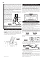
The upper louvres must be removed to allow the door to be
opened or closed. To access the lower door latch, open
the valve control door. Release the top and bottom door
latches, located at the right side of the door.
FINISHING
L36 LOUVRE INSTALLATION
DOOR REMOVAL & INSTALLATION
FIGURE 35 a-c
HOOD
Attach the hood by pressing the
top flange into the clips along
the top of the louvre opening.
Secure using a screw through
the centre slot.
LOWER LOUVRES
Insert the hinge clips into the
slots located at the bottom left
and right corners of the unit.
To remove the louvres, pull the
back tabs of the clips forward,
while pushing the louvre assem-
bly back. Lift the clip.
UPPER LOUVRES
Insert the louvre tabs into the
slots located at the top left and
right corners of the unit.
SLOT
TAB
B
C
HINGE
CLIP
SLOT
FIGURE 34
A
CLIPS
CENTRE
SLOT
FLANGE
Note: The protective wrap is best removed when the
assembly is at room temperature but this can be improved
if the assembly is warmed, using a hair dryer or similar
source.

20
W415-0484 / A / 07.26.06
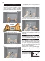
PHAZER
TM
logs and glowing embers exclusive to Napoleon Fire-
places, provide a unique and realistic glowing effect that is
different in every installation. Take the time to carefully po-
sition the glowing embers for a maximum glowing effect.
Log colours
may vary. During the initial use of the fireplace,
the colours will become more uniform as colour pigments
burn in during the heat activated curing process.
1. Place the rear log against the locator, pushing down,
until it rests on the base, infront of the tabs.
2. Move the two small logs (#2 & #3) into position, lining
up the studs located on the burner with the holes on the
bottom of the logs. Ensure that the small logs sit flat on the
burner.
REARVIEW
LOCATOR
TAB
TAB
LOG PLACEMENT
Randomly place the charcoal embers along the front and
sides of the log support tray in a realistic manner. Fine dust
found in the bottom of the bag should not be used.
Tear the embers into pieces and place along the front row
of ports covering all of the burner area in front of the small
logs (#2 & #3). Care should be taken to shred the embers
into thin, small irregular pieces as only the exposed edges
of the fibre hairs will glow. The ember material will only
glow when exposed to direct flame; however, care should
be taken to not block the burner ports.
Blocked burner ports can cause an incorrect flame pattern,
carbon deposits and delayed ignition. PHAZER
TM
logs glow
when exposed to direct flame. Use only certified "glowing
embers" and PHAZER
TM
logs available from your Napo-
leon dealer.
Remove the backing of the
logo supplied and place on the
glass viewing door, as
indicated.
CHARCOAL EMBERS
GLOWING EMBERS
LOGO PLACEMENT
3. Place the bottom of the left crossover log (#4) onto the
locating stud on the left side of the log support.
The top of the log should rest in the pocket on the rear log.
4. Position the heel of log #5 into the slot in the centre of
the log support. ther end of the log rests in the pocket of the
left log.
5. Place the bottom of the right crossover log (#6) onto
the locating stud on the right side of the log support. The
top of the log should rest in the pocket provided on the
center log (#5).
FIGURE 37a-d
#1
#2 #3
#4
#5
#6
½"
½"
LOGO
FIGURE 38
Page is loading ...
Page is loading ...
Page is loading ...
Page is loading ...
Page is loading ...
Page is loading ...
Page is loading ...
Page is loading ...
Page is loading ...
Page is loading ...
-
 1
1
-
 2
2
-
 3
3
-
 4
4
-
 5
5
-
 6
6
-
 7
7
-
 8
8
-
 9
9
-
 10
10
-
 11
11
-
 12
12
-
 13
13
-
 14
14
-
 15
15
-
 16
16
-
 17
17
-
 18
18
-
 19
19
-
 20
20
-
 21
21
-
 22
22
-
 23
23
-
 24
24
-
 25
25
-
 26
26
-
 27
27
-
 28
28
-
 29
29
-
 30
30


Napoleon Fireplaces B36DFN User manual
- Category
- Fireplaces
- Type
- User manual
- This manual is also suitable for
Ask a question and I''ll find the answer in the document
Finding information in a document is now easier with AI
Related papers
-
Napoleon Fireplaces StarFire GD70PT-S User manual
-
-
-
-
-
-
-
-
-
Other documents
-
NAPOLEON B36DFP Installation And Operation Instructions Manual
-
-
-
-
Vollrath Cover, Inset, Hinged Installation guide
-
White Rodgers H06E030S1 User manual
-
NAPOLEON BGNV42P User manual
-
Everbilt BPGH4WHD6 Operating instructions
-
-
 Drolet Nova 820 User manual
