Page is loading ...

OPERATING AND INSTALLATION
OPERACIÓN E INSTALACIÓN
UTILISATION ET INSTALLATION
DHW HEAT PUMP WATER HEATER
CALENTADOR DE AGUA CON BOMBA ELÉCTRICA DE CALOR
CHAUFFE-EAU THERMODYNAMIQUE
»ACCELERA® 300
A 280011-36221-8653
STIEBEL ELTRON Inc.
17 West Street | West Hatfi eld MA 01088
Tel. 413-247-3380 | Fax 413-247-3369
Email info@stiebel-eltron-usa.com
www.stiebel-eltron-usa.com
The Accelera
®
300 Heat
Pump Water Heater is tested
and certifi ed by WQA against
NSF/ANSI 372 for lead free
compliance.

2 | ACCELERA® 300 HEAT PUMP WATER HEATER WWW.STIEBEL-ELTRON-USA.COM
GENERAL INFORMATION
QUICK START-UP GUIDE
GENERAL INFORMATION
Please read
Read these instructions carefully and retain them for
future reference. If the water heater is passed on to
a third party please hand these instructions to the
new user.
This manual includes important information regarding the safe
and effi cient handling of the water heater. Keep this manual with
the water heater at all times.
Work must only be carried out by a licensed installer who has read
and understands these instructions. All federal, state, and local
codes must be followed. Failure to do so may result in equipment
failure, serious injury, or death.
While working on the water heater, disconnect the power supply.
Illustrations in these instructions are designed to aid a general
understanding and may deviate from the actual water heater
version. No claims can be derived from such illustrations.
Limited liability:
We have collated all details and information in this manual in due
consideration of applicable standards and regulations, the state of
the art and our long-term know-how and experience.
Losses due to the following are excluded from our liability:
- Non-observance of these instructions
-Incorrect use
- Installation of the water heater by unqualifi ed personnel
- Unauthorized modifi cations
- Technical modifi cations
- Use of unauthorized spare parts
Copyright:
These operating and installation instructions are subject to
copyright.
Transferring these instructions to third parties, copying of any
kind, either in total or extracts therefrom, as well as their use
and/or conveying its contents are prohibited without our written
consent.
Contraventions are liable to claims for compensation. Further
claims are reserved.
We hold the copyright:
STIEBEL ELTRON Inc.
17 West Street | West Hatfi eld MA 01088
Tel. 413-247-3380 | Fax 413-247-3369
Email info@stiebel-eltron-usa.com
www.stiebel-eltron-usa.com
Should you have any question regarding the installation or
operation of the water heater, please contact our customer service.
Tel. (USA) 800-582-8423 or 413-247-3380
Please record your serial number and information
Serial No.:
____________________________________________________________________
Date of Purchase:
____________________________________________________________
Accelera
®
300 Quick Start-up Guide
A. OVERVIEW: This water heater hooks up like any other electric water heater, with a few minor exceptions. Be sure to follow
all state and local codes during installation. This page is not intended to be a substitute for the installation manual. Be
sure to follow all safety precautions.
B. UNPACKING: DO NOT unpack water heater unit until it is located at the point of installation. Follow all instructions in the
manual and be sure to use caution, as this unit is top heavy. DO NOT lay the unit down and DO NOT jar or tip the unit past
45 degrees on the hand truck. See: 10.6
C. INSTALLATION / WATER:
a. Location: Find a suitable location according to the manual. Minimum area is 10’ x 10’ x 8’. Be sure vents are parallel to
the wall with the fan facing the most open area along that wall. Please note: a drain pan is recommended. See: 10.6
b. 3/4” Inlet from union provided. For hook-up, follow all state and local codes for check valves, expansion tanks, shut off
valves, gauges, etc. Install a 70 psi pressure reduction valve.
Please note: water pressure should not exceed 0.48 MPa (70 psi). See: 10.7
c. 3/4” Outlet from union to hot water line.
d. Install T&P Relief valve (supplied). Please note: 0.69 MPa / 99 °C (100 psi / 210 °F).
D. CONDENSATE DRAIN: Goes directly into a drain or use a condensate pump to drain into a suitable location. See: 10.6.1
E. FILL & FLUSH TANK: Run water and be sure tank is full prior to turning on the electricity.
F. INSTALLATION / ELECTRICAL: Use a 240 Volt / 15 Amp double pole breaker and connect to water heater L1, L2, and
Ground. See: 16.2
!
WITHIN ABOUT 5 HOURS OF START-UP TIME, EXHAUST
AIR FLOW SHOULD BE APPROXIMATELY -14,4°C (6°F)
LESS THAN THE INLET SIDE.
CAUTION: RISK OF SCALDING.
THERE IS A RISK OF SCALDING AT OUTLET
TEMPERATURES EXCEEDING 43°C (110°F) RISK OF
SCALDING

ENGLISH
WWW.STIEBEL-ELTRON-USA.COM ACCELERA 300 | 3
QUICK START-UP GUIDE | OPERATION
H
M
C
Cold water
Hot water
2
12
15
13
14
11
3
4
5
6
7
8
9
10
1
1 Vacuum breaker
2 Hot water connection (Union adaptor to 3/4")
3 Mixing valve (optional, supplied by installer)
4 Connection for T&P valve ¾"
5 T&P valve ¾", 0.69 MPa @99 °C (100 psi @210 °F) (supplied with unit)
6 0.551 MPa (80 psi) relief valve (optional, supplied by installer)
7 Expansion tank (optional, supplied by installer)
8 Straight-through shut-off valve (supplied by installer)
9 Check valve (optional, supplied by installer)
10 0.48 MPa (70 psi) pressure reduction valve (optional, supplied by installer)
11 Cold water connection (with Union adaptor to 3/4")
12 Condensate drain (elbow supplied with unit)
13 Drain valve (supplied by installer)
14 Drain pan (supplied by installer)
15 Condensate spillover

4 | ACCELERA® 300 HEAT PUMP WATER HEATER WWW.STIEBEL-ELTRON-USA.COM
CONTENTS | OPERATION
GENERAL INFORMATION ____________________________________________2
QUICK START-UP GUIDE ____________________________________________2
OPERATION __________________________________________________________5
1. Overview ____________________________________________________5
2. General information ________________________________________5
2.1. Key to symbols ___________________________________________________ 5
3. Safety ________________________________________________________9
3.1. General safety instructions ____________________________________ 9
3.2. Intended use ______________________________________________________ 9
3.3. Incorrect use ______________________________________________________ 9
3.4. Personnel qualifi cation _________________________________________ 9
3.5. Safety equipment ________________________________________________ 9
3.6. Particular risks ___________________________________________________ 9
4. Water heater description _________________________________ 10
4.1. Function description ___________________________________________ 10
5. Operation __________________________________________________ 10
5.1. Initial start-up by a licensed installer ______________________ 10
5.2. Starting and stopping __________________________________________ 10
5.3. Emergency stop _________________________________________________ 10
6. Maintenance and care ____________________________________ 10
6.1. Descaling _________________________________________________________ 11
7. What to do if ... ___________________________________________ 11
7.1. ... the water heater does not deliver hot water ___________ 11
7.2. ... the safety valve of the cold water supply line is
dripping __________________________________________________________ 11
7.3. ... the condensate drain drips ________________________________ 11
7.4. ... the power consumption is too high ______________________ 11
7.5. ... the room temperature drops excessively _______________ 11
7.6. ... other faults occur ____________________________________________ 11
8. Safety ______________________________________________________ 11
8.1. General safety instructions ___________________________________ 11
8.2. Incorrect use _____________________________________________________ 12
8.3. Qualifi cation _____________________________________________________12
8.4. Instructions, standards and regulations ___________________ 12
8.5. Water installation _______________________________________________ 12
8.6. Electrical installation___________________________________________ 12
9. Water heater description _________________________________ 12
9.1. Standard delivery _______________________________________________ 13
9.2. Special accessories _____________________________________________ 13
10. Installation ________________________________________________ 13
10.1. Installation location ____________________________________________ 13
10.2. Shipping inspection ____________________________________________ 14
10.3. Handling __________________________________________________________ 14
10.4. Storage ____________________________________________________________ 14
10.5. Positioning the water heater _________________________________ 14
10.6. Unpacking the water heater __________________________________ 14
10.7. Water connection _______________________________________________ 17
10.8. Power supply: 240V / 15A double pole circuit breaker __ 17
11. Initial start-up ____________________________________________ 19
11.1. Initial start-up ___________________________________________________ 19
11.2. Shutting down ___________________________________________________ 19
11.3. Restarting ________________________________________________________ 19
12. Settings ____________________________________________________ 19
12.1. Adjusting the water temperature ____________________________ 19
13. Water heater hand over __________________________________ 19
14. Troubleshooting ___________________________________________ 19
14.1. Safety equipment of the water heater ______________________ 19
14.2. Troubleshooting _________________________________________________ 20
15. Maintenance and cleaning _______________________________ 20
15.1. Cleaning the evaporator ______________________________________ 20
15.2. Draining the tank _______________________________________________ 20
15.3. Sacrifi cial anode rod ___________________________________________ 20
15.4. Descaling _________________________________________________________ 20
15.5. Checking valves _________________________________________________ 21
16. Specifi cation _______________________________________________ 21
16.1. Connection and dimensions __________________________________ 21
16.2. Wiring diagram _________________________________________________ 22
16.3. Refrigerant diagram ___________________________________________ 23
16.4. Technical Data ___________________________________________________ 24
WARRANTY ________________________________________________________ 27
ENVIRONMENT AND RECYCLING _________________________________ 27

OPERATION
OVERVIEW
ENGLISH
WWW.STIEBEL-ELTRON-USA.COM ACCELERA® 300 HEAT PUMP WATER HEATER | 5
1. Overview
Front of the water heater
7
6
2
5
4
3
1
26_03_01_1338
4
4
8
1 Water heater cover
2 Opening for PT valve
3 Condensate drain
4 Leveling feet
5 Cold water inlet
6 Hot water outlet
7 Air entry
8 Condensate spillover
An 80 gallon water tank is part of the water heater. Foam insulation
is applied to the outside of the water tank to prevent heat losses.
The water heater casing is made from powder-coated sheet steel.
The internally enameled water tank is supported by three height-
adjustable anti-vibration leveling feet.
OPERATION
Back of the water heater
9
10
26_03_01_1337
9 Air discharge
10 Entry for the power cable
11 Information labels, serial no.:
11

OPERATION
GENERAL INFORMATION
6 | ACCELERA® 300 HEAT PUMP WATER HEATER WWW.STIEBEL-ELTRON-USA.COM
2. General information
The chapter Operation is intended for users and licensed installers.
The chapter Installation is intended for licensed installers only.
2.1 Key to symbols
2.1.1 Layout of safety information
DANGER Electric shock
Before any work on the water heater,
disconnect all poles from the power
supply.
e
e
e
e
e
e
e
e
e
e
e
e
e
e
e
e
po
p
p
p
p
p
p
p
p
p
p
p
wer
1
3
4
2
1 Symbol (see chapter "Symbols")
2 Keyword (see chapter "Keywords")
3 Designations (see chapter "Symbols")
4 Information text
2.1.2 Symbols
Symbol Description
Injury
Electrocution
Burns or scalding
!
Other situations
Fire
Explosion
Water heater disposal
2.1.3 Keywords
KEYWORD
DANGER The keyword DANGER indicates information
that must be observed, otherwise serious injury
or death
will result.
WARNING The keyword WARNING indicates information
that must be observed, otherwise serious injury
or death
may result.
CAUTION The keyword CAUTION indicates information
that must be observed, otherwise relatively
serious or light injuries may result.
2.1.4 Symbols in this documentation
Read the text next to this symbol carefully.
» Passages with the symbol "»" indicate that you have to do
something. The action you need to take is described step by
step.
- Passages with this symbol "–" indicate lists.
2.1.5 Units of measure in this documentation
The dimensions in this document are given in
millimeters (inches).
2.1.6 Information on the packaging
Information label "Top heavy"
!!
Hoher Schwerpunkt
High balance point
Hoog zwaartepunt
Centre de gravité en partie haute
Hög tyngdpunkt
Alto centro di graviá
Alto centro de gravedad
Achtung - Attention - Attentie - Attention
Uppmärksamhet - Oppmerksomhet
Attenzione - Atención
+
264623-33631
Information label "Vertical transport"
!CHTUNG!TTENTION
4RANSPORTUND!UFSTELLUNG
$AMITDAS'ERËTVOR"ESCHËDIGUNGENGESCHàTZTISTSOLLTEESBISANDEN-ONTAGEORTINDER6ERPACKUNGTRANSPORTIERTWERDEN'ERËTSENKRECHTTRANSPORTIEREN"EI
BEENGTEN4RANSPORTBEDINGUNGENKANNDAS'ERËTAUCHKURZZEITIGGENEIGTWERDEN"EACHTEN3IEDIEWEITEREN(INWEISEZUM!UFSTELLENUND!USRICHTENDES'ERË
TESINDERBEILIEGENDEN'EBRAUCHSUND-ONTAGEANWEISUNGUM3CHËDENAM'ERËTZUVERMEIDEN
4RANSPORTANDINSTALLATION
4OPROTECTTHEEQUIPMENTAGAINSTDAMAGEITMUSTBETRANSPORTEDINSIDEITSDEDICATEDPACKAGINGUNTILTHEINSTALLATIONFACILITYISARRIVED4RANSPORTTHEEQUIPMENT
UPRIGHT7HERESPACEISRESTRICTEDYOUMAYALSOMOVEBRIEFLYTHEEQUIPMENTTIPPEDBACKWARDSATANANGLE/BSERVETHENOTESONINSTALLATIONANDFITTINGOFTHE
EQUIPMENTWHICHCANBEFOUNDINTHEENCLOSEDINSTALLATIONANDOPERATINGINSTRUCTIONSTOAVOIDPOSSIBLEDAMAGETOTHEEQUIPMENT
'ERËTNURSENKRECHTODERGGFGENEIGTTRANSPORTIEREN
-OVETHISMACHINEONLYINAVERTICALPOSITIONORIFREQUIREDSLIGHTLYINCLINEDWITHTHECONTROLFACIAPOINTUP
!C
H
T
UNG
!TTENTION
4RANSPORTUND!UFSTELLUNG
$AMITDAS'ERËTVOR"ESCHËDIGUNGENGESCHàTZTISTSOLLTEESBISANDEN-ONTAGEORTINDER6ERPACKUNGTRANSPORTIERTWERDEN
PGPG
'
ERËTSENKRECHTTRANS
P
ORTIEREN
"EI
BEENGTEN4RANSPORTBEDINGUNGENKANNDAS'ERËTAUCHKURZZEITIGGENEIGTWERDEN"EACHTEN3IEDIEWEITEREN(INWEISEZUM!UFSTELLENUND!USRICHTENDES'ERË
GG G G P G P
GG G G P G P
P
P
TESINDERBEILIEGENDEN'EBRAUCHSUND-ONTAGEANWEISUNGUM3CHËDENAM'ERËTZUVERMEIDEN
GPGG GGG
GPGG GGG
4RANSPORTANDINSTALLATION
4OPROT
ECTTHE
EQUIPM
ENTAGA
INSTDA
MAGEI
TMUSTBETRAN
SPORTED
INSIDEITSDEDICATED
PACKAG
INGUNT
ILTHEINSTALLATIONF
ACILITY
ISARRIVED
PP
4RANSPORTTHEEQUIPMENT
UPRIGHT
P
P
7HERESPACEISRESTRICTEDYOUMAYALSOMOVEBRIEFLYTHEEQUIPMENTTIPPEDBACKWARDSATANANGLE/BSERVETHENOTESONINSTALLATIONANDFITTINGOF
THE
QP G G P P GG Y
QP G G P P GG Y
P
QP
P
QP
EQUIPMENTWHICHCANBEFOUNDINTHEENCLOSEDINSTALLATIONANDOPERATINGINSTRUCTIONSTOAVOIDPOSSIBLEDAMAGETOTHEEQUIPMENT
PGG
PYY YQPPP G
PYY YQPPP G
'ERËTNURSENKRECHTODER
GG
F
G
ENEI
G
TTRANSPORTIEREN
-OVETHISMACHINE
ONLYI
NAVERTICAL
POSIT
IONORIFR
EQUIRE
DSLI
GHTLY
INCLINEDWITHTHECONTROLFACI
APOIN
TUP
280306-34594

OPERATION
GENERAL INFORMATION
ENGLISH
WWW.STIEBEL-ELTRON-USA.COM ACCELERA® 300 HEAT PUMP WATER HEATER | 7
2.1.7 Information on the water heater
For reason
of
corrosion
protection
use flat
gasket ring
28030 5 - 35826
BURN
HOT
CAUTION
DANGER
!
284760-34684
WW Austritt
DHW outlet
280304-34684
mus e e o e c eary mar e
socket. The valve drain outlet pipe
must not be sealed or blocked, and the
valve easy gear is to be operated
at least once every six month.
28
0
5
58-
34684
Drain
280302-34812
KW Eintritt
CW Inlet
280303-
3
46845
For reason
of
corrosion
protection
use flat
gasket ring
28030 5 - 35826
Drain
28
0
3
0
2-34812
lief valve
ber:
relief valve installation
t be fitted to this socket.
280557-35826
2
4
6
1
7
3
5
26_03_01_1355
2
8
0
3
0
4
-
3
4
6845
3
1
1 Information label "Condensate drain"
2 Information label "Risk of scalding"
3 Information label "Connection"
4 Information label "Hot water outlet"
5 Information label "Relief valve"
6 Information label "Relief valve installation location"
7 Information label "Cold water inlet"
Power supply
Disconnect power supply
before opening the cover.
280556-34684
Type: Accelera 300/WHP 300
Heat pump:
PN (Air 42° / Water 60°):
IN (Air 42° / Water 60°):
Type of Refrigerant:
Refrigerant charge:
Max. operating pressure:
Lock rotor current:
MCA:
Rated load compressor:
Motor fan:
Order-No.: 222423
DHW-cylinder:
Additional heating element:
Max. operating pressure:
Max. operating temperature:
Type of cylinder material:
Cylinder capacity:
Observe the installation manual! Tested for lea
No.: 8443 / 005204
Voltage / Frequency:
Breaker:
P (rated power input):
Maximum allowable ratings
Protection class:
Nmax
Single phase 220-240 V, 50/60 Hz
15 amp.
2200 W, 9.17 A
IP 24
*222423844300520415*
1690 W
87 psi /600 kPa
168.8 °F /76 °C
Glass lined steel
80.044 Gal /303 l
0.5 kW
2.17 A
R134A
1.9842 Lb. /900 g
348.1 psi /2.4
13.4 A
10.4 A
2.3 A
38 W
: on a ns uorna gr se gases cover y yoo rooco - rme cay sea .
FR: Comprend les gaz à effet de serre fluorés enregistrés par le protocole de Kyoto - systèmes hermétiquement scellés.
NL: Bevat gefluoreerde broeikasgassen die onder het Kyoto-protocol vallen - hermetisc
SE: Innehåller av Kyoto - protokollet registrerade flourerande växthusgaser i hermetisk
PL: Zawiera fluorowane gazy cieplarniane ujęte w Protokole z Kioto - hermetycznie za
CZ: Obsahuje fluorizované skleníkové plyny, obsažené v Kjótském protokolu - hermeti
8
11
26_03_01_1356
10
9
8 Information label "Power connection"
9 Type plate
10 Information label "Fluorated gases"
11 Information label "Energy effi ciency"
1 Information label "Condensate drain"
This label shows you the position where the water heater drain
is located.
Drain
280302-34812
D
r
a
i
n
2
8
0
3
0
2-
3
4
8
12
280302-34812.
2 Information label "Risk of scalding"
BURN
HOT
CAUTION
CAUTION
DANGER
!
284760-34684
284760-34684.
3 Information label "Connection"
For reason
of
corrosion
protection
use flat
gasket ring
28030 5 - 35826
280305-35826

OPERATION
GENERAL INFORMATION
8 | ACCELERA® 300 HEAT PUMP WATER HEATER WWW.STIEBEL-ELTRON-USA.COM
4 Information label "Hot water outlet"
WW Austritt
DHW outlet
280304-34684
W
W
A
u
s
t
r
i
t
t
D
H
W
o
u
t
l
e
t
2
8
0
3
0
4
-
3
4
68
4
280304-34684
5 Information label "Relief valve"
Warning
A
temperature and pressure relief valve
must be fitted to the clearly marked
socket. The valve drain outlet pipe
must not be sealed or blocked, and the
valve easy gear is to be operated
at least once every six month.
280558-34684
W
a
r
n
i
n
g
A
t
e
m
p
e
r
a
t
u
r
e
a
n
d
p
r
e
s
s
u
r
e
r
e
l
i
e
f
v
a
l
v
e
m
u
s
t
b
e
f
i
t
t
e
d
t
o
t
h
e
c
l
e
a
r
l
y
m
a
r
k
e
d
s
o
c
k
e
t
.
T
h
e
v
a
lv
e
d
r
a
i
n
o
u
t
l
e
t
p
i
p
e
m
u
s
t
n
o
t
b
e
s
e
a
l
e
d
o
r
b
l
o
c
k
e
d
,
a
n
d
t
h
e
v
a
l
v
e
e
a
s
y
g
e
a
r
i
s
t
o
b
e
o
p
e
r
a
t
e
d
a
t
l
e
a
s
t
o
n
c
e
e
v
e
r
y
s
i
x
m
o
n
t
h.
2
8
0
5
5
8
-
3
4
68
4
280558-34684
6
Information label "Relief valve installation location"
Relief valve
Plumber:
The relief valve installation
must be fitted to this socket.
280557-35826
R
e
l
i
e
f
v
a
l
v
e
P
l
u
m
b
e
r
:
T
h
e
r
e
l
i
e
f
v
a
l
v
e
in
s
t
a
ll
a
ti
on
m
u
s
t
b
e
f
i
t
t
e
d
t
o
t
h
i
s
soc
k
e
t.
2
8
0
5
5
7-
358
2
6
280557-35826
7 Information label "Cold water inlet"
KW Eintritt
CW Inlet
280303-34684
K
W
E
i
n
t
r
i
t
t
C
W
I
n
l
e
t
2
8
0
3
0
3
-
3
4
68
4
280303-34684
8 Information label "Power connection"
Power supply
Disconnect power supply
before opening the cover.
280556-346842
P
o
w
e
r
s
u
p
p
l
y
D
i
s
c
o
n
n
e
c
t
p
o
w
e
r
s
u
p
p
l
y
b
e
f
o
r
e
o
p
e
n
i
n
g
t
h
e
c
o
v
e
r
.
2
8
0
5
5
6
-
3
4
68
4
2
280556-34684
9 Type plate
Type: Accelera 300/WHP 300
Heat pump:
PN (Air 42° / Water 60°):
IN (Air 42° / Water 60°):
Type of Refrigerant:
Refrigerant charge:
Max. operating pressure:
Lock rotor current:
MCA:
Rated load compressor:
Motor fan:
Order-No.:
222423
DHW-cylinder:
Additional heating element:
Max. operating pressure:
Max. operating temperature:
Type of cylinder material:
Cylinder capacity:
Test pressure storage tank:
Observe the installation manual! Tested for leaks!
Made in Germany
No.: xxxx / xxxxxx
Voltage / Frequency:
Breaker:
P (rated power input):
Limits for heat pump operation:
Maximum allowable ratings
Protection class:
Nmax
Single phase 220-240 V, 50/60 Hz
15 amp.
6 °C / + 4 2 °C
2200 W, 9.17 A
IP 24
*222423xxxxxxxxxxxx*
1690 W
87 psi /
600 kPa
168.8 °F / 76
°C
Glass lined steel
80.044 Gal /303 l
130.5 psi / 900 kPa
0.5 kW
2.17
A
R134a
1.9842 Lb. /900 g
348.1 psi /2.4
MPa
13.4 A
10.4 A
2.3 A
38 W
STIEBEL ELTRON INC
17 West Street
West Hatfield, MA 01088
USA
282209
-35793
26_03_01_1357
10 Information label "Fluorated gases"
DE: Enthält vom Kyoto - Protokoll erfasste fluorierte Treibhausgase - hermetisch geschlossenes System.
GB: Contains fluorinated greenhouse gases covered by the Kyoto Protocol - hermetically sealed.
FR: Comprend les gaz à effet de serre fluorés enregistrés par le protocole de Kyoto - systèmes hermétiquement scellés.
NL: Bevat gefluoreerde broeikasgassen die onder het Kyoto-protocol vallen - hermetisch gesloten systeem.
SE: Innehåller av Kyoto - protokollet registrerade flourerande växthusgaser i hermetiskt förslutna system.
PL: Zawiera fluorowane gazy cieplarniane ujęte w Protokole z Kioto - hermetycznie zamknięty układ.
CZ: Obsahuje fluorizované skleníkové plyny, obsažené v Kjótském protokolu - hermeticky uzavřený systém.
ES: Sistema herméticamente cerrado que contiene gases de efecto invernadero mencionados en el protocolo de Kioto.
DK: Indeholder fra Kyoto-protokollen registrerede, fluorerede drivhusgasser – hermetisk lukket system.
NO: Inneholder fluorerte drivhusgasser som omfattes av Kyotoprotokollen - hermetisk lukket system.
FI: Sisältää Kioton sopimuksen alaisia fluorattuja kasvihuonekaasuja - ilmatiiviisti suljettu järjestelmä.
284436-34741
BG: Съдържа посочените в Протокола от Киото флуорирани парникови газове - херметически затворена система.
HU: A Kiotói Jegyzıkönyv szerinti fluortartalmú üvegházhatású gázokat tartalmaz - hermetikusan zárt rendszer.
IT: Contiene gas fluorurati ad effetto serra disciplinati dal protocollo di Kyoto - Impianto ermeticamente chius.
RO: Conține un sistem închis ermetic contra emisiei de gaze fluorine monitorizat de protocolul Kyoto.
26_03_01_1386
11 Information label "Energy effi ciency"
282980-36142
Maintain the legibility of all information labels.
Illegible safety information and symbols can result in
dangerous situations.

OPERATION
SAFETY
ENGLISH
WWW.STIEBEL-ELTRON-USA.COM ACCELERA® 300 HEAT PUMP WATER HEATER | 9
3. Safety
This chapter provides an overview of all important actions required
for a safe and trouble-free operation.
3.1 General safety instructions
Operate the water heater only when fully installed and with all
safety equipment in place.
Unsuitable tools or incorrect handling can result in damage to
the water heater.
DANGER Scalding
The water is heated inside the water tank to60 °C
(140 °F). There is a risk of scalding at outlet
temperatures above 43 °C (109 °F).
» Ensure that outfl owing water does not directly
contact your body.
CAUTION Injury
Where children or persons with limited physical,
sensory or mental capabilities are allowed to control
this water heater, ensure that this will only happen
under supervision or after appropriate instruction by
a person responsible for their safety.
» Children should be supervised to ensure that they
never play with the water heater.
Never place any objects on top of the water heater.
Objects placed on top of the water heater can increase
the noise level developed by the water heater through
vibrations.
Never cover the water heater.
The water heater draws in air. Covering the inlet slots
reduces the air intake. This reduces the effi ciency of
the water heater and can even lead to one of the safety
devices interrupting the water heater operation.
3.2 Intended use
This water heater produces hot water automatically.
The water heater can be installed and operated in the open as well
as in enclosed spaces. The temperature of the air that is drawn in
during operation must not fall below 6 °C (43 °F).
Any other use beyond that described shall be deemed inappropriate.
Observation of these instructions is also part of the correct use of
this water heater.
Any changes or modifi cations to this water heater void all warranty
rights.
3.3 Incorrect use
The following are not permitted:
- Do not heat anything other than potable water
- Do not use unqualifi ed (unlicensed) personnel for installation
- Do not use in an environment with greasy extract air
This water heater must not be operated at ambient
temperatures in excess of 42 °C (107 °F) or below 6 °C
(43 °F).
If outside air is directly drawn in ensure, that the
water heater is isolated from its power supply when
the air temperature falls below 6 °C (43 °F).
3.4 Personnel qualifi cation
DANGER Injury
Incorrect handling can result in severe injuries and
material losses. Inadequately qualified personnel
cannot assess the potential risks.
Have the installation, initial start-up, maintenance
and repair steps carried out only by the qualifi ed
individuals specifi ed in the respective chapters.
In the remainder of this manual, such qualifi ed individuals will be
described as the "licensed installer."
3.5 Safety equipment
Wear safety shoes/boots during the transportation and positioning
of the water heater. Dry, this water heater weighs 130 kg (290 lb).
Safety shoes/boots reduce the risk of injury.
3.6 Particular risks
3.6.1 Electric current
WARNING Electric shock
Contacting parts that carry live power is associated
with a direct risk to life. Damaging the insulation or
individual components can result in a risk to life.
» If you detect damaged insulation, immediately
switch off the power supply and arrange for the
necessary repair.
» Have all electrical work carried out by a qualifi ed
electrician.
3.6.2 Hot surfaces
CAUTION Burning
Contact with hot components can result in burning.
» When working near hot components, wear
protective clothing and gloves.
» The pipework connected to the hot water outlet of
the water heater can reach temperatures in excess
of 60 °C (140 °F).
3.6.3 Refrigerant
The water heater is fi lled with R134A refrigerant at the factory.
WARNING Freezer burn
Should the water heater leak refrigerant, avoid contact
with the refrigerant or breathing in any released
vapors. Immediately vent the room.
In normal water heater operation, the refrigerant is contained in
a sealed circuit.

OPERATION
WATER HEATER DESCRIPTION
10 | ACCELERA® 300 HEAT PUMP WATER HEATER WWW.STIEBEL-ELTRON-USA.COM
4. Water heater description
This water heater is an automatic hot water generator with approx.
303l (80gallon) capacity. The hot water temperature is factory
set to 60 °C (140 °F).
After opening a hot water faucet, the hot water is pushed out of
the water heater by the incoming cold water.
This water heater works like an air conditioner but does not need
to be vented. The water heater extracts heat from the ambient air
to heat the water. The demand for electrical energy and the heat-
up time depend on the ambient air temperature and humidity.
When installing the water heater inside, the space where it is
installed will be cooled down during the operation by 1 to 3 °C
(2 to 6 °F).
The water heater also extracts moisture from the air that creates
condensate, which must be drained off. For this purpose, a
condensate drain is integrated in the water heater. This is where
you can connect a hose to a drain.
To protect the steel tank against corrosion, the interior is coated
with a special enamel and is equipped with a replaceable sacrifi cial
anode.
Heat pump function:
A sealed circuit inside the water heater contains R134A refrigerant
(see "Specifi cation/data table"); this does not deplete ozone, is
non-fl ammable, and evaporates at low temperatures.
In the evaporator, where heat is extracted from the outside air,
the refrigerant changes from its liquid into its gaseous state. A
compressor draws in the gas in and compresses it. The increase
in pressure raises the refrigerant temperature and heats the water
tank.
This process requires electrical energy. The energy (motor heat)
is not lost, but reaches the condenser downstream together with
the compressed refrigerant. Here, the gas transfers heat to the
water tank. An expansion valve then reduces the pressure and
the process starts again.
4.1 Function description
4.1.1 Heat pump operation
The heat pump unit located on top of the water heater extracts
heating energy from the ambient air.
If the water heater was separated from the power
supply during operation, the compressor will only
restart if the pressure inside the refrigerant circuit has been
balanced. Pressure balance can only be created after waiting
15 minutes.
4.1.2 Booster heater
Primarily, the water inside the tank is heated by the heat pump.
When there is a higher hot water demand or when the water heater
was switched OFF and you require hot water quickly, the integral
booster heater will turn on. To save energy, the booster heater
only heats the top third of the tank (approx. 102 l (27 gallons)).
A thermostat switches the booster heater on if the water
temperature inside the tank falls below 45 °C (112 °F). A thermostat
switches the booster heater off if the water temperature inside the
tank exceeds 60 °C (140 °F).
4.1.3 Defrosting
The lower limit of use of the water heater is permanently set to
6 °C (42 °F). It is possible that at this limit, the evaporator will be
coated in frost. This is subject to the air temperature and humidity
level, particularly at low hot water temperatures.
The compressor will be switched off as soon as the evaporation
temperature falls below -7 °C (20 °F) for any length of time. When
the temperature at the evaporator fi ns rises above 3 °C (38°F), the
compressor starts again, and the hot water heating continues. The
fan continues to run during defrosting.
5. Operation
You do not have to make any adjustments. The water heater
is therefore not equipped with any controls. The hot water
temperature is factory set to 60 °C (140 °F).
Should you wish to operate with different settings, contact your
local licensed installer.
WARNING Scalding
The water is heated inside the water tank to
60 °C (140 °F). There is a risk of scalding at outlet
temperatures in excess of 42 °C (108 °F).
Ensure that outfl owing water does not directly contact
your body.
5.1 Initial start-up by a licensed installer
Initial start-up should be done by a licensed installer.
5.2 Starting and stopping
The water heater is not equipped with an ON/OFF switch. If a
power plug was fi tted during installation, you can disconnect
the water heater from the power supply by pulling that plug.
Alternatively, you can terminate the water heater operation by
tripping the circuit breaker.
5.3 Emergency stop
In case of emergency, carry out the following steps:
» Isolate the power supply by tripping the circuit breaker or by
pulling the power plug.
» Shut off the cold water inlet.
6. Maintenance and care
A damp cloth is suffi cient for cleaning the exterior of the water
heater. Never use abrasive or corrosive cleaning agents. Do not
hose down the water heater.
» Monthly, check that the condensate drain is clear.
» Monthly, carry out a visual inspection of the condensate
pan drain (in the top of the water heater; see the following
diagram). Look through the air intake grille at the front of the
water heater. If required, notify your local licensed installer
who will remove any contamination.

OPERATION
WHAT TO DO IF ...
ENGLISH
WWW.STIEBEL-ELTRON-USA.COM ACCELERA® 300 HEAT PUMP WATER HEATER | 11
1
26_03_01_1404
1 Condensate pan drain
6.1 Descaling
At high temperatures water separates out lime. This is deposited
on the inside of the tank. With increasing limescale build-up, the
amount of hot water inside the tank is reduced.
» Have a licensed installer descale the booster heater from
time to time. This extends the service life of the booster
heater.
» Scale cannot build up on the heat pump element.
A licensed installer who knows the local water quality will tell you
when the next maintenance appointment is due.
» Have your licensed installer check the sacrifi cial anode
regularly.
7. What to do if ...
7.1 ... the water heater does not deliver hot
water
» Check the water heater power supply.
» Check your fuse box for a tripped circuit breaker.
» Make sure there is a 15A double pole circuit breaker
If the circuit breaker has tripped, reset it or replace it. Notify your
local licensed installer if the circuit breaker trips again.
» Ensure that the air intake and air discharge are unobstructed.
Excessively high ambient temperature, excessively high
temperature of the air drawn in (>42 °C (108 °F)) or a fault in the
refrigerant circuit can result in the compressor being overloaded.
The thermal protective 'auto reset' motor switch or the high limit
'manual reset' cut-out can both shut off the compressor off.
The high limit pressure limiter must only be reset by
your licensed installer after they have removed the
cause of the relevant fault.
After a short cooling down period, the thermal protective motor
auto reset switch will restart the compressor automatically.
Notify your local licensed installer if the water heater does not
restart automatically.
7.2 ... the safety valve of the cold water supply
line is dripping
This unit can operate up to 0.48 MPa (70psi) of inlet pressure.
Expansion water drips from the safety valve during heat-up. This
is completely normal. Notify your local licensed installer if water
still drips after heat-up has been completed.
7.3 ... the condensate drain drips
This is quite normal and always happens when the surface
temperature of the evaporator is lower than the dew point
temperature of the ambient air.
7.4 ... the power consumption is too high
Please consult a qualifi ed licensed installer.
7.5 ... the room temperature drops excessively
The water heater operation reduces the ambient air by
1 to 3°C (2 to 6°F). Notify your local licensed installer if the
ambient temperature drops abnormally.
7.6 ... other faults occur
Notify your local licensed installer. Refer to the water heater
number on the type plate next to the barcode.
Type: Accelera 300/WHP 300
Heat pump:
PN (Air 42° / Water 60°):
IN (Air 42° / Water 60°):
Type of Refrigerant:
Refrigerant charge:
Max. operating pressure:
Lock rotor current:
MCA:
Rated load compressor:
Motor fan:
Order-No.:
222423
DHW-cylinder:
Additional heating element:
Max. operating pressure:
Max. operating temperature:
Type of cylinder material:
Cylinder capacity:
Test pressure storage tank:
Observe the installation manual! Tested for leaks!
Made in Germany
No.: xxxx / xxxxxx
Voltage / Frequency:
Breaker:
P (rated power input):
Limits for heat pump operation
:
Maximum allowable ratings
Protection class:
Nmax
Single phase 220-240 V, 50/60 Hz
15 amp.
6 °C / +42 °C
2200 W, 9.17 A
IP 24
*222423xxxxxxxxxxxx*
1690 W
87 psi /
600 kPa
168.8 °F /
76
°C
Glass lined steel
80.044 Gal /303 l
130.5 psi / 900 kPa
0.5 kW
2.17 A
R134a
1.9842 Lb. /900 g
348.1 psi /2.4 MPa
13.4 A
10.4 A
2.3 A
38 W
STIEBEL ELTRON INC
17 West Street
West Hatfield, MA 01088
USA
282209
-35793
26_03_01_1357
1
1 Water heater number
8. Safety
Only qualifi ed licensed installers should carry out installation,
initial start-up, maintenance and repair of the water heater.
8.1 General safety instructions
Use only original accessories and spare parts intended for this
water heater.
DANGER Electric shock
Disconnect the water heater from the power supply
prior to its installation.
WARNING Injury
If the pipes inside the water heater are damaged,
leaking refrigerant gas can result in severe physical
freezer burns.
Do not inhale refrigerant. Immediately vent the room
thoroughly.
» Wear safety goggles and gloves during water heater
installation.
INSTALLATION

OPERATION
WATER HEATER DESCRIPTION
12 | ACCELERA® 300 HEAT PUMP WATER HEATER WWW.STIEBEL-ELTRON-USA.COM
WARNING Injury
Moving parts represent a risk of injury.
» Before opening the water heater, ensure that the fan
has come to a complete standstill.
8.2 Incorrect use
The following are not permitted:
- Do not install the water heater on non-load bearing fl oors
- Do not install the water heater where it is at risk from frost
- Do not install in rooms where the water heater is at risk from
explosions as a result of dust, gases or vapors
- Do not ignore safety clearances and safety zones
- Do not incorrectly install the power connection
- Do not operate the water heater with the tank empty
- Do not operate the water heater with an open casing
- Do not heat anything other than potable water
- Do not fi ll with any other Freon, use only R134A
8.3 Qualifi cation
WARNING Injury
Incorrect handling can result in severe injuries and
material losses. Inadequately qualified personnel
cannot assess the impending danger.
Have only personnel mentioned in the appropriate
sections of this manual carry out specifi c measures.
In this manual, such qualifi ed individuals will be described as the
"licensed installer".
Licensed installers are responsible for adherence to all currently
applicable regulations during installation and initial start-up.
8.3.1 Licensed installer
Licensed installers are specially trained in their fi eld. Licensed
installers work on systems on the basis of their training, knowledge
and experience, as well as their knowledge of applicable standards
and regulations. They are able on their own to recognize and
prevent possible problems.
8.3.2 Electrician (licensed)
An electrician is a licensed installer who meets the above
requirements with regard to electrical installations.
8.3.3 Plumber (licensed)
A plumber is a licensed installer who meets the above requirements
with regard to water-related installations.
8.3.4 Customer service
For customer service inquiries, please contact Stiebel Eltron
directly at 1-800-582-8423, ext. 25 or ext. 33.
8.4 Instructions, standards and regulations
Follow all national, state, and local codes.
Observe the regulations of your local energy and water supply
utilities.
The following standards were taken into account:
UL 499, UL 1995, UL 94-5 VA, UL 174
IEC 60335-1-2-40, IEC 61000-3-2; 1995
IEC 61000-3-3, IEC 55014-1 IEC 55014-2
EMC Directive 89/336/EEC
EN 255 T3
Read the water heater type plate and the chapter "Specifi cation".
8.5 Water installation
The following materials may be used:
- Cold water line: steel, copper or plastic pipework.
- Hot water line: copper or plastic pipework.
» Ensure that no contamination reaches the water heater
through the pipework.
8.6 Electrical installation
Protect the water heater electrically with a 15A double pole circuit
breaker.
Where the water heater is permanently connected to the power
supply, it must be able to be separated from the mains power
supply by an additional isolator that disconnects all poles with
at least 3 mm (0.12") contact separation. For this purpose, use
contractors, circuit breakers, fuses, etc. on site.
In case of a fault, the safety equipment interrupts the relevant
power circuit.
9. Water heater description
3
2
1
4
5
26_03_02_1404
1 High limit safety cut-out - manual reset
2 Compressor
3 Condensate drain
4 Filter dryer
5 Service valve, high pressure
6 Sacrifi cial anode
6

ENGLISH
WWW.STIEBEL-ELTRON-USA.COM ACCELERA® 300 HEAT PUMP WATER HEATER | 13
INSTALLATION
INSTALLATION
8
7
9
10
26_03_02_1405
7 Capacitor
8 Fan
9 Evaporator
10 Defrost sensor
The hot water thermostat temperature is preset at the
factory.
Where customers require a lower hot water
temperature, the thermostat settings of the heat pump
and the booster heater can be reduced.
A sacrifi cial anode rod is installed in the top of the water heater. (6)
9.1 Standard delivery
- Accelera 300 heat pump water heater
- Two adaptors, Union to ¾"
- Two union gaskets
9.2 Special accessories
Description Part number
Anode rod 278235
Segmented anode rod 143498
10. Installation
CAUTION Injury
Incorrect installation can result in severe injuries and
material losses.
Prior to installation ensure you have adequate space
for the work to be carried out.
Handle components with sharp edges carefully.
The sheet steel casing of the water heater is not
designed to withstand heavy forces.
Handle and install the water heater with care.
10.1 Installation location
DANGER Explosion
Never install the water heater in rooms where it is
at risk from explosions as a result of dust, gases or
vapors.
WARNING Injury
The room where the water heater is to be installed
must have a load-bearing fl oor. There is a risk of
the water heater breaking through the fl oor if the
substrate has insuffi cient load-bearing capacity. The
wet weight of the water heater is approx. 430 kg (950
lb).
If the fl oor offers inadequate load-bearing capacity,
there is a risk of the water heater breaking through
the fl oor, resulting in a risk to life.
Risk of frost damage
Install the water heater only in an area free from the
risk of frost. When the water heater is not in use and
there is a risk of frost, the water inside the water tank
can freeze and damage the tank.
- Never install the water heater in areas where the air
temperature regularly drops below 6 °C (42 °F) or rises above
42 °C (108 °F).
- To prevent nuisance through operating noise, never install
the water heater in the vicinity of bedrooms. Prevent noise
emissions towards a neighbor.
- Allow adequate space around the water heater for
installation, maintenance and cleaning tasks.
With internal installations, also observe the following:
- The available fl oor area in the installation room must be at
least 6 m² (10' x 10' - 100 ft²). The room volume must not be
less than 13 m³ (500 ft³).
- The water heater must not be restricted by walls and
ceilings. The required minimum clearances are specifi ed in
chapter "Positioning the water heater/positioning conditions"
(see chapter 10.5, "Positioning the water heater")..
- Observe that the room temperature will drop by 1to3 °C (2
to 6 °F) as a result of the water heater operation.
- When installing the water heater in a furnace room, ensure
that the furnace operation will not be impaired.
- To keep line runs as short as possible, we recommend that
the water heater is installed near the kitchen or bathroom.

14 | ACCELERA® 300 HEAT PUMP WATER HEATER WWW.STIEBEL-ELTRON-USA.COM
INSTALLATION
INSTALLATION
10.2 Shipping inspection
» Upon receipt, check your delivery for completeness and
possible transport damage.
If transport damage is visible, proceed as follows:
- Do not accept the delivery or only with reservations.
- Note down the extent of the damage on the shipping
documents or on the delivery note of the carrier.
- Initiate a complaint.
Immediately give notice of any damage.
Give notice of all damage as soon as it has been
identifi ed. Claims can only be accepted within the
applicable claim period.
10.3 Handling
CAUTION Injury through heavy loads
Dry, this water heater weighs 130 kg (290 lb.). Use
suitable aids and suffi cient personnel when handling
this water heater.
Risk of damage through incorrect handling.
Incorrect handling can result in substantial material
losses.
Observe the information on the packaging.
Remove the packaging just before the installation.
Risk of damage through overturning.
The water heater has a high centre of gravity and a
low overturning moment. Protect the water heater
against overturning.
Only position the water heater on a level substrate.
To protect the water heater against damage, it should be
transported vertically inside its packaging. Where space is
restricted, you can also tilt (max. 45°) the water heater briefl y
to move it.
10.4 Storage
Where it is necessary to store the water heater prior to installation
for a longer period, observe the following:
- If possible, store the water heater in a dry and dust-free
ambience.
- Prevent the water heater from coming into contact with
aggressive materials.
- Prevent the water heater from being exposed to shocks or
vibrations.
- In case of prolonged storage, check the condition of the
water heater and its packaging regularly.
10.5 Positioning the water heater
» Position the water heater with its wooden pallet at the fi nal
installation location in a 10’ x 10’ x 8’ area.
Install the water heater so that there is an adequate clearance
adjacent to the air grilles (see the following diagrams).
10.5.1 Installation conditions
It is important for the water heater maintenance that adequate
space remains available above the water heater.
(15,75")
(15,75")
(7,87")
(15,75")
D0000018502
» Level the water heater horizontally by adjusting the feet.
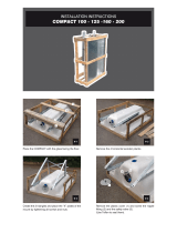
10.6 Unpacking the water heater
Ensure that the casing material in the lower section
will not be damaged.
Advice - The longer you keep the packaging foil
wrapped around the water heater, the longer it will
be protected against damage.
» Remove the packaging straps.
» Push the packaging foil far enough upwards that the pallet is
freely accessible.
» Remove the water heater carefully with the polystyrene
®
packaging from the pallet.
DANGER Injury from tipping over
The water heater has a high centre of gravity and a
low overturning moment. Ensure that the water heater
does not overturn when you remove it from its pallet.
» Slide the packaging foil far enough upwards to be able to
remove the fi rst polystyrene
®
profi les from the sides. These
polystyrene
®
profi les on the sides are used as installation
aids in the following steps.

ENGLISH
WWW.STIEBEL-ELTRON-USA.COM ACCELERA® 300 HEAT PUMP WATER HEATER | 15
INSTALLATION
INSTALLATION
26_03_01_1395
» Separate the lower packaging section at the dividing line.
For this, make an incision of approx. 30 mm (1.25") into both
sides of the dividing line.
26_03_01_1396
» Slightly tilt the water heater.
6
DANGER Injury from overturning
Secure the water heater against overturning by
getting a second person to support the water heater.
» Push a wooden support underneath the lower part of the
packaging.
» Break out the free semi-shell of the lower section of the
packaging.
» Keep the water heaters slightly tilted.
» Wind out the free leveling foot, but not by more than 30mm
(1.1").
» Turn the locking nut on the thread of the leveling foot
towards the bottom cover. When the locking nut is tight
against the bottom cover, it stabilizes the leveling foot.
26_03_01_1384
» Push two polystyrene
®
installation aids with the step-shaped
corner underneath the water heater. The water heater is
subsequently set and tilted onto this profi le. Ensure that you
do not set the water heater down in the area of the joint edge
of the sheet steel jacket, but at least 150 mm (6") along.

16 | ACCELERA® 300 HEAT PUMP WATER HEATER WWW.STIEBEL-ELTRON-USA.COM
INSTALLATION
INSTALLATION
26_03_01_1388
» Tilt the water heater that has been set down on the
polystyrene
®
installation aids.
» Remove the remaining fl oor semi-shell.
» In the tilted state of the water heater, wind out the second
and third leveling foot, but not by more than 30 mm (1.1").
» In both cases, tighten the locking nut against the bottom
cover.
» Position the water heater on the three leveling feet.
» Level the water heater vertically by adjusting the three
leveling feet.
» Remove any packaging that remains on the water heater.
» Install condensate drain elbow.
10.6.1 Condensate drain
26_03_01_1127
1
< 889 (35")
2
3
4
5
3
3
6
1 Condensate drain or
2 Drain pan connected to drain
3 T&P valve
4 Cold water connection
5 Hot water connection
6 Condensate spillover
The condensate drain is located on the side of the water heater.
This is where you can connect a drain hose.
When installing the unit outdoors, the condensate can drain off
freely.
For indoor installation, the condensate can be routed into a fl oor
drain or routed through the wall up to 889mm (35") (see diagram
above).
If required, install a condensate pump.
To ensure the condensate drains correctly, never kink
the hose.

ENGLISH
WWW.STIEBEL-ELTRON-USA.COM ACCELERA® 300 HEAT PUMP WATER HEATER | 17
INSTALLATION
INSTALLATION
10.7 Water connection
The water connection must be carried out by a qualifi ed licensed
plumber.
The cold water connection must comply with DIN1988 [or state
and local codes]
» Prior to installing the water heater, fl ush the line thoroughly.
H
M
C
1
1
1
1
1
1
1
1
1
1
5
6
2
3
4
Cold water
7
8
9
10
Hot water
13
14
12
11
26_03_01_1123
15
1 Vacuum breaker
2 Hot water connection (Union adaptor to 3/4")
3 Mixing valve (optional, supplied by installer)
4 Connection for T&P valve ¾"
5 T&P valve ¾", 0.69 MPa @99 °C (100 psi @210 °F) (supplied
with unit)
6 0.551 MPa (80 psi) relief valve (optional, supplied by
installer)
7 Expansion tank (optional, supplied by installer)
8 Straight-through shut-off valve (supplied by installer)
9 Check valve (optional, supplied by installer)
10 0.48 MPa (70 psi) pressure reduction valve (optional,
supplied by installer)
11 Cold water connection (with Union adaptor to 3/4")
12 Condensate drain (elbow supplied with unit)
13 Drain valve (supplied by installer)
14 Drain pan (supplied by installer)
15 Condensate spillover
» Remove the protective rubber caps from the connectors.
» With a sharp knife, cut a hole into the protective caps and
install them over the pipe to be connected.
» Connect the plumbing.
» After connecting the plumbing, connect the protective caps
so that the sheet steel casing of the water heater grips into
the outer groove of the protective cap.
Risk of damage through corrosion
To protect against the risk of corrosion, make the
connection with fl at gaskets.
» Insulate the hot water line against heat loss.
» Install a drain valve at the lowest point of the cold water
supply.
Install a 0.48 MPa (70 psi) pressure reducing valve on the cold
water inlet.
Accurately maintain the order of fi ttings on the cold water side
(see diagram 10.7).
10.7.1 Safety valve (on-site provision)
This water heater is a sealed unit. A 0.69MPa, 99°C (100psi,
210°F) T&P relief valve must be installed.
When installing the T&P valve, observe the following:
- Size the drain line so that water can drain off completely,
even if the safety valve is fully open.
- The drain outlet must not be able to be closed and must
always remain open to atmosphere.
- The T&P valve must open at a pressure of 0.69MPa (100 psi)
and be 3/4" pipe thread.
10.7.2 T&P valve (on-site provision)
WARNING Risk of injury through excessive pressure
and temperatures.
Install safety equipment that meets the applicable
regulations for the installation locations. In any case
install a "Pressure and Temperature Relief valve (T&P
relief)" that complies with the requirements of the
ANSIZ21.22 ("Requirements for Relief Valves and
Automatic Gas Shut-off Water heaters for Hot Water
Supply Systems").
The T&P valve must respond at a pressure of 0.69MPa
(100 psi). Fit the T&Pvalve into the opening on the
circumference of the water heater indicated.
Ensure that any expelled water cannot come into
contact with 'live' parts and will not run onto sensitive
surfaces. Ensure that the T&P valve outlet remains
free at all times.
10.8 Power supply: 240V / 15A double pole
circuit breaker
The electrical connection must be carried out by a qualifi ed
electrician.
DANGER Electric shock
Contacting 'live' components results in a risk to life.
» Disconnect the water heater from the power supply
before carrying out work on the control panel.
» Be sure that no one can reconnect the power while
you are working.
When making a connection use code compliant disconnects.
» Undo the screws and remove the water heater cover.

18 | ACCELERA® 300 HEAT PUMP WATER HEATER WWW.STIEBEL-ELTRON-USA.COM
INSTALLATION
INSTALLATION
Air fl ow
→
Air fl ow
→
Risk of electric shock
Use copper conductors only
Ris
Us
11
10
4
6
3
1
16
15
13
12
8
7
14
9
5
4
26_03_01_1406
2
CAUTION :
CAUTION :
Risk of electric shock
Risk of electric shock
Use copper conductors only
Use copper conductors only
1 Capacitor
2 Cable entry into the water heater casing
3 Strain relief (cable clamp)
4 Mains terminal
5 Frost monitor
6 Heat pump control thermostat
7 Fan motor
8 Heat pump terminal
9 Thermostat, booster heater
10 High limit safety cut-out, booster heater,
manual reset (see 14.1.1)
11 Booster heater
12 Sacrifi cial anode
13 Safety pressure limiter, manual reset,
(see 14.1.2)
14 Condensate pan drain
15 Compressor
16 Compressor motor protection (Klixon),
delay auto reset (see 14.1.3)
» Pull the power cable through the cable entry into the water
heater interior.
» Route the power cable through the strain relief (cable
clamp).
» Connect the power cable to the mains terminal in accordance
with the wiring diagram (see chapter 16.2 "Wiring Diagram".
L1, L2 and ground).
WARNING Electric shock
Risk of injury through inadequate grounding.
» Ensure that the water heater is correctly grounded
in accordance with the requirements at the place of
installation.
The ground conductor of the power cable must be
connected to the terminal marked G or Earth.
10.8.1 High limit safety cut-out
At ambient temperatures below -10 °C (14 °F), for example during
shipping or in storage, the high limit safety cut-out may trip.
Press the reset button of the high limit safety cut-out to reset it.
To do this, fi rst remove the water heater cover.
1
26_03_01_1151
1 Reset button for high limit safety cut-out

ENGLISH
WWW.STIEBEL-ELTRON-USA.COM ACCELERA® 300 HEAT PUMP WATER HEATER | 19
INSTALLATION
INITIAL START-UP
11. Initial start-up
11.1 Initial start-up
Only approved, licensed installers may perform the initial start-up
of this water heater, and instruct the user in its operation.
» Fill and vent the water heater. For this, open the cold water
supply and one hot water tap.
» Thoroughly fl ush the water heater.
» Check the safety valves. Inform the user that water may drip
from the safety valve while water is being heated up.
» Connect power by resetting the circuit breaker.
This water heater must not be operated at ambient
temperatures below 6 °C (43 °F) or above42 °C (107 °F).
11.2 Shutting down
The water heater can only be switched off by disconnecting the
power supply.
11.3 Restarting
If power has been switched off or interrupted, wait 15 minutes
before turning unit back on.
12. Settings
12.1 Adjusting the water temperature
The water temperature must only be adjusted by a licensed
installer, as the cover must be removed from the water heater.
3
26_03_01_1151
1
2
1 Thermostat, heat pump operation
2 Thermostat of the booster heater
3 High limit safety cutout
The temperature is reduced by turning the thermostat counter-
clockwise.
Adjust both thermostats to the same setting.
Energy consumption will rise if the temperature is set
lower at the heat pump thermostat than at the booster
heater thermostat.
Ensure that both thermostats are adjusted to the same setting.
Energy consumption will rise if the temperature is set lower at the
heat pump thermostat than at the booster heater thermostat. The
booster heater must be set equal to or lower than the heat pump.
12.2 Knob settings
Heat pump
125 °F
Backup element
120 °F
13. Water heater hand over
» Explain the functions to the user. Draw special attention to
the safety information.
» Hand these operating instructions to the user.
14. Troubleshooting
WARNING Electric shock
Always disconnect the power supply before working
on the water heater.
14.1 Safety equipment of the water heater
If faults develop, the safety cutouts on the water heater will
interrupt the appropriate power circuits.
14.1.1 High limit safety cut-out for booster heater
The high limit safety cut-out protects the water heater against
overheating. The booster heater is switched off when the
temperature of the water inside the tank exceeds 95 °C (203 °F).
After removing the source of the fault, press the reset button on
the high limit safety cut-out. To do this, fi rst remove the water
heater cover. See below.
14.1.2 Safety pressure limiter for heat pump
2
26_03_02_1306
1 Reset button for the high limit safety cutout
2 Reset button for the safety pressure limiter
1

20 | ACCELERA® 300 HEAT PUMP WATER HEATER WWW.STIEBEL-ELTRON-USA.COM
INSTALLATION
MAINTENANCE AND CLEANING
The safety high pressure limiter shuts down the compressor if
the pressure inside the refrigerant circuit exceeds the permissible
maximum value. The safety high pressure limiter may also trip if
the water heater is operated above its permissible limit, i.e. above
an air temperature of 42 °C (107 °F). (See above)
The safety pressure limiter also trips if the heat pump thermostat
fails.
» After the cause of the fault has been removed, reset the
safety pressure limiter by pressing the reset button.
14.1.3 Protective motor switch - klixon
The protective motor switch will shut down the compressor if it is
overloaded because of excessive thermal load. Remove the cause.
After a short cool-down phase, the protective motor switch will
restart the compressor automatically.
14.2 Troubleshooting
14.2.1 Excessive power consumption
» Lower the temperature of the booster heater.
14.2.2 The room temperature falls excessively
One possible cause is an inadequate air fl ow over the evaporator.
» Check the fan.
» Check for clogged evaporator.
» Ensure that the intake and discharge fl ow are not restricted.
15. Maintenance and cleaning
Only qualifi ed licensed installers must carry out maintenance work
in accordance with these instructions.
WARNING Electric shock
Maintenance work, such as checking the electrical
safety, must only be carried out by an electrician.
Always disconnect the power supply before working
on the water heater.
15.1 Cleaning the evaporator
WARNING Injury
The evaporator has many sharp-edged fi ns. When
cleaning the evaporator, proceed with caution and
wear protective clothing, in particular safety gloves.
Maintaining the full output of the water heater at all times requires
an occasional professional cleaning of the evaporator.
» Undo the screws that connect the water heater cover and
remove.
» Carefully clean the evaporator fi ns. Only use water and a soft
brush. Never use acidic or alkaline cleaning agents.
15.2 Draining the tank
WARNING Scalding
Hot water can be expelled when draining the tank.
» Close the shut-off valve in the cold water line.
» Fully open the hot faucets at all points.
The tank is drained via the cold water supply. Some residual water
will remain in the bottom of the tank.
» Open the drain valve (see chapter 10.7, "Water connection").
If a drain valve was not installed, undo the fi tting on the cold water
supply of the water heater.
15.3 Sacrifi cial anode rod
A sacrifi cial anode rod is inserted in the top of the water heater.
The sacrifi cial anode rod fi tted at the factory is approx. 1260 mm
(50") long.
The timing of the anode inspection is subject to the local water
quality and is determined by your local licensed installer. We
recommend that the anode is checked no later than 12months
after initial start-up.
CAUTION :
Risk of electric shock
Use copper conductors only
26_03_01_1025
1
1 Sacrifi cial anode rod
If the anode is used up, you will need to replace it. Should it prove
impossible to install an anode rod (length approx. 1260 mm (50")),
install a segmented anode.
Description Part #
Anode rod 278235
Segmented anode rod 143498
During the anode rod installation ensure a clean metal-conducting
connection between the anode and the tank.
/