Page is loading ...

© 2018 DELTA T LLC ALL RIGHTS RESERVED.
AIG-INST-217-ENG-01 REV. A
AIRGO MISTING SYSTEM MAINTENANCE
WARNING: Disconnect the fan and misting pump from power before servicing.
Service schedule
Schedule Procedure
50 hours of operation Initial oil change
300 hours of operation
Change the oil.
If ISO 68 Crankcase Oil Special Formula Premium Grade is used, change the oil
after every 500 hours of use. Contact Customer Service to purchase.
1,500 hours of
operation
Change the seals.
If system performance decreases, check immediately. If no wear is observed,
check again after 2,000 hours of operation.
3,000 hours of
operation
Change the relief valve.
Service the relief valve at every other seal change and check connections
before resuming.
Monthly
Check the oil level.
Check for oil and water leaks.
Annually
Clean the misting nozzles.
To prevent clogs caused by mineral deposits, clean the misting nozzles annually
using a commercial mineral deposit cleaner such as Orbit
®
Misting Nozzle
Cleaner or Lime-A-Way
®
. Depending on the mineral content of the water, the
nozzles may need to be cleaned more frequently. Check the nozzles regularly
for clogs. Observe each nozzle to ensure it is producing an even cone of mist. If
any nozzles are spraying irregularly, clean the nozzles. See the following page
for cleaning instructions.
Seasonally
Winterize the misting pump seasonally if it will be stored in temperatures at or
below 32° F (0° C).
To winterize the misting pump:
1. Flush the pump with fresh water.
2. Press the relief valve to relieve line pressure. Disconnect the water supply
hose from the filter and disconnect the high pressure hose from the top of
the fan.
3. Flush the system by connecting a short hose to the pump inlet. Place the
other end of the hose in a container with half water and half antifreeze.
4. Operate the pump until antifreeze runs through the high pressure hose.
5. Disconnect power from the pump. Cover and store the pump in an
appropriate location.
To restart the pump, reconnect the water supply hose and power supply. Turn
on the pump for 2–3 minutes and check for leaks.

© 2018 DELTA T LLC ALL RIGHTS RESERVED.
AIG-INST-217-ENG-01 REV. A
Draining and storing
If the misting system will be unused or stored for more than one week, drain the water out of the system after
you are finished using it.
To reconnect the high pressure hose to the misting pump, apply thread seal tape, such as Teflon
®
tape, to
the threads on the end of the hose, and then screw the hose back into the pump outlet.
To drain the misting system:
1. Tilt the fan cage forward 90° so that the cage is horizontal to the ground and the front of the cage is facing
the ground.
2. Disconnect the high pressure hose from the misting pump outlet.
3. Unscrew the filter from the misting pump inlet.
4. Allow the system to drain completely before storing.
If the misting system has been turned o for more than 24 hours, clear out the system by running it for one
minute before use. This ensures clean water is flowing through the system before people come into contact with
the mist.
Cleaning the misting nozzles
Clean the misting nozzles annually to prevent clogs caused by mineral deposits.
To clean a misting nozzle:
1. Unscrew and remove the nozzle from the misting rail.
2. Disassemble the nozzle as shown below. Clean all parts of the nozzle using a commercial mineral deposit
cleaner such as Orbit
®
Misting Nozzle Cleaner or Lime-A-Way
®
. Be sure to clean the nozzle’s internal mesh
screen. Refer to the illustration below.
3. Reassemble the nozzle as shown below.
4. Apply a commercial thread sealant to the nozzle’s threads. The sealant should be approved for 1,000 PSI
of water and must work with plastic. Loctite
®
1537780 No More Leaks
™
Plastic Pipe Thread Sealant or Oatey
®
31230 Great White
®
Pipe Joint Compound with PTFE are recommended.
5. Screw the nozzle back into the misting rail and tighten to 60 in·lb (6.8 N·m).
Mesh
Screen
Replacing misting nozzles
To replace a misting nozzle, unscrew the original nozzle from the misting rail. Screw the replacement nozzle into
the rail and tigthen to 60 in·lb (6.8 N·m). Repeat as needed to replace additional nozzles.

© 2018 DELTA T LLC ALL RIGHTS RESERVED.
AIG-INST-217-ENG-01 REV. A
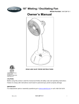
Internal pump parts diagram and parts list
174
172
169
167
166
164
163
168
167
166
161
160
188
185
310
125
121
120
99
300
106
98
90
100
70
65
64
32
24
33
53
5
38
37
49
48
200
255
10
11
8
15
20
25
27
400
408
410
415
412
427
429
440
402
403
# Description Qty # Description Qty # Description Qty
5
Screw, Bearing Cover (M6 x 14)
3 65
Rod, Plunger
1 174
Plug, Valve with 1/4’” NPTF Port
1
8
Cover, Bearing
1 70
Seal, Oil (70D)
1 185
Head, Manifold
1
10
O-Ring, Bearing Cover (70D)
1 90
Plunger (M16 x 27)
1 188
Screw, HSH (M6 x 55)
4
11
Seal, Oil (70D)
1 98
Washer, Seal (90D)
1 200
Hose, Pulse (3/8” x 24”)
1
15
Bearing, Inner Ball
1 99
Retainer, Plunger (M6 x 35)
1 255
Assembly, Bolt Mount
1
20
Rod, Connecting
1 100
Retainer, Seal
1 300
Kit, Seal (Includes 98, 106, 121, & 125)
1
24
Plug, Oil Cap
1 106
Seal, LPS with S-Spg (85D)
1 310
Kit, Valve (Includes 160, 161, 163, 164,
166, 167, 168, 169, & 172)
1
25
Crankshaft (6.3 mm)
Crankshaft (2 mm)
Crankshaft (3.3 mm)
1
1
1
120
Case, Seal
1 400
Regulator
1
121
O-Ring, Seal Case (70D)
1 402
Cap, Hex Adjusting
1
125
Seal, HPS (85D)
1 403
Nut, Locking
1
27
Bearing, Outer Ball
1 160
O-Ring, Inlet Seat (70D)
1 408
Spring
1
32
Cap, Oil Filter with O-Ring
1 161
Seat, Inlet
1 410
Retainer, Spring
1
33
O-Ring, Oil Filler Cap (70D)
1 163
O-Ring, Discharge Seat (70D)
1 412
Stem, Piston
1
37
Sight Gauge (80D)
1 164
Seat, Discharge
1 415
O-Ring, Piston Stem (70D)
1
38
Gasket, Flat Flex, Oil Gauge (80D)
1 166
Valve
2 427
Seat
1
48
Plug, Drain
1 167
Spring
2 429
O-Ring, Seat (70D)
1
49
O-Ring, Drain Plug (70D)
1 168
Retainer, Inlet Spring
1 440
Body
1
53
Crankcase
1 169
Retainer, Discharge Spring
1 468
Kit, O-Ring (Includes 172, 415, & 429)
1
64
Pin, Crosshead
1 172
O-Ring, Discharge Fitting (70D)
1

© 2018 DELTA T LLC ALL RIGHTS RESERVED.
AIG-INST-217-ENG-01 REV. A
Changing the oil
A drain pan and ISO 68 Crankcase Oil Special Formula Premium Grade are required when changing the oil.
Refer to the pump parts diagram for item number identification.
To change the oil on the misting pump:
1. Remove the drain plug (48) on the bottom of the pump. Allow the oil to drain into the drain pan, and then
replace the drain plug (48).
2. Remove the oil cap (32) on top of the pump.
3. Pour ISO 68 Crankcase Oil Special Formula Premium Grade oil into the opening until the oil level reaches
the red dot on the sight gauge (37).
4. Replace the oil cap (32).
Servicing the regulator
An O-Ring kit, M22 wrench, and an M6 allen wrench are required to service the regulator. Refer to the pump
parts diagram for item number identification.
To disassemble the regulator:
1. Disconnect the discharge and bypass hoses from the pressure regulator (400).
2. Loosen the hex valve plug (174) with an M22 wrench, and then remove the pressure regulator (400) from the
manifold head (185). Note: Do not separate the pressure regulator from the hex valve plug.
3. Remove the black adjusting cap (402) with an M6 allen wrench by turning it counterclockwise.
4. Remove the exposed coil spring (408) and flat spring retainer (410).
5. Carefully remove the piston stem (412) and o-ring (415).
6. Remove the seat (427) and o-ring (429).
To inspect and reassemble the regulator:
1. Examine the seat (427) and o-ring (429) for pitting or wear. Replace if damaged.
2. Lubricate and install the o-ring (429) on the seat (427), and then press the seat into the regulator chamber
with the small diameter down until it is squarely seated.
3. Examine the piston stem (412) and o-ring (415) for grooves, pitting, or wear. Replace if damaged.
4. Lubricate and install the o-ring (415) on the piston stem (412), and then lower the piston stem into the
regulator chamber with the tapered end facing downward.
5. Examine the flat spring retainer (410) and coil spring (408) for fatigue or breaks. Replace if damaged.
6. Place the flat spring retainer (410) and spring (408) on top of the piston stem (412).
7. Hold the locking nut (403) on top of the spring (408), and then thread the black adjusting cap (402) into the
locking nut (403).
8. Reconnect the bypass and discharge lines to the regulator (400).

© 2018 DELTA T LLC ALL RIGHTS RESERVED.
AIG-INST-217-ENG-01 REV. A
Servicing the plunger
An M10 hex tool and Loctite
®
Threadlocker Blue 242
®
are required to service the plunger. Refer to the pump
parts diagram for item number identification.
To disassemble the plunger:
1. Remove the four hex socket head screws (188) from the manifold head (185).
2. Support the manifold head from the underside, and pull the manifold head away from the crankcase (53).
3. Set aside the manifold head (185) with the crankcase side up.
4. Remove the seal retainer (100) from the plunger rod (65).
5. Loosen the plunger retainer (99) on the plunger rod (65) approximately three to four turns with an M10 hex
tool.
6. Push the ceramic plunger (90) toward the crankcase (53) to separate it from the plunger retainer (99).
Unthread the plunger retainer (99) by hand.
7. Remove the ceramic plunger (90) and seal washer (98) from the plunger retainer (99).
To inspect and reassemble the plunger:
1. Inspect the crankcase oil seal (70) for deterioration or leaks. If damaged, contact Customer Service for a
replacement, and refer to “Servicing the Crankcase.”
2. Examine the seal washer (98) and the plunger retainer (99) for damage. Replace if damaged.
3. Install the seal washer (98) on the plunger retainer (99).
4. Examine the ceramic plunger (90) for scoring, scale buildup, chips, or cracks. Replace if damaged. Note: The
ceramic plunger does not need to be replaced with every seal servicing.
5. Slide the plunger retainer (99) with the seal washer (98) into the flat end of the ceramic plunger (90).
6. Apply Loctite
®
Threadlocker Blue 242
®
to the exposed, threaded end of the plunger retainer (99).
7. Install the ceramic plunger (90) with the plunger retainer (99) and seal washer (98) on the plunger rod (65)
shoulder. Torque to 4.6 ft·lb (6.2 N·m). Note: The ceramic plunger can only be installed in one direction. The
counterbore end of the ceramic plunger fits over the plunger rod shoulder.
8. Press the Lo-Pressure seal (106) into the seal case (120) with the garter spring down.
9. Examine the ceramic plunger (90) for cracks or scale buildup. Replace if damaged.
10. Slide the seal retainer (100) over the ceramic plunger (90) with the drain slots facing the crankcase (53) and
the openings upwards and downwards.
11. Lightly lubricate the ceramic plunger (90). Carefully slide the manifold head (185) over the ceramic plunger,
supporting it from the underside to avoid damage. Press the manifold head until it is flush with the crankcase
(53).
12. Thread the four hex socket head screws (188) into the manifold head. Torque the screws to 5.2 ft·lb (7 N·m)
in the sequence shown below.
1 3
24
Torque
Sequence

© 2018 DELTA T LLC ALL RIGHTS RESERVED.
AIG-INST-217-ENG-01 REV. A
Servicing the crankcase
An M10 hex tool and Loctite
®
242
®
are required to service the crankcase. Refer to the pump parts diagram for
item number identification.
To service the crankcase:
1. Remove the manifold head (185), plunger (65), and retainer (99). See “Servicing the Plunger” for disassembly
instructions.
2. Examine the crankcase oil seal (70) for leaking or damage.
3. Check for signs of leaking around the bearing cover (8), drain plug (48), and sight gauge (37).
4. Check the oil level and for evidence of water in the oil. Ensure the oil is changed regularly according to the
service schedule.
5. Examine the crankshaft oil seal (11) for drying, cracking, or leaking. If damaged or leaking, contact Customer
Service.
Servicing the inlet/discharge valve
An M22 wrench and M8 screw are needed to service the valve. Refer to the pump parts diagram for item
number identification. Note: The inlet valve seat, o-ring, and inlet spring retainer are dierent than the discharge
valve seat, o-ring, and discharge spring retainer.
To disassemble the valve:
1. Disconnect the discharge and bypass lines from the pressure regulator (400).
2. Loosen the hex valve plug (174) with an M22 wrench, and then remove the regulator (400) from the manifold
head (185). Note: The pressure regulator does not need to be separated from the hex valve plug.
3. Remove the stacked valve assembly (310) from the valve chamber.
4. To separate the valve assemblies, thread an M8 screw into the bottom of the seat (161) until the screw
contacts the bottom of the valve (166).
If the discharge valve assembly separates from the inlet valve assembly during removal, use pliers to remove
the inlet valve assembly from the valve chamber.
If the inlet spring retainer (168) separates from the inlet seat (161), remove the spring (167) and valve (166)
from the valve chamber. Thread an M8 screw into the inlet seat (161) and remove it from the valve chamber.
5. Remove the o-rings (172, 163) from the seats (161, 164) and valve plug (174).
To inspect and reassemble the valve assembly:
1. Reassembly can be done using a new, pre-assembled valve assembly (A) or using parts (B).
A. Press the pre-assembled valve assembly (310) into the valve chamber until fully seated. Skip to step 8.
B. If reassembling using individual parts, proceed to step 2.
2. Examine the springs (167) for fatigue or breaks. Replace if damaged.
3. Examine the valve (166) and seats (161, 164) for grooves, pitting, or wear. Replace if damaged.
4. Examine the valve plug (174) and o-ring (172) for cuts or wear. Replace if damaged.
5. Lubricate and install the o-ring (163) on the outside diameter of the discharge seat (164). Set aside the
discharge seat with the small diameter facing downward.
6. Place the valve (166) on the discharge seat (164) with the concave side down, and then place the spring (167)
on the valve.
7. Place the discharge spring retainer (169) over the spring (167) and snap it to the discharge seat (164).
8. Assemble the inlet valve assembly in the same order as above, and then snap the discharge valve assembly
on the inlet valve assembly. Press the entire assembly into the valve chamber until seated.

© 2018 DELTA T LLC ALL RIGHTS RESERVED.
AIG-INST-217-ENG-01 REV. A
Servicing the seal kit
An M5 allen wrench and a new seal kit are required to service the seal kit. Contact Customer Service for a
replacement seal kit. Refer to the pump parts diagram for item number identification.
To disassemble the seal kit:
1. Remove the four hex socket head screws (188) from the manifold head (185).
2. Support the manifold head from the underside, and pull the manifold head away from the crankcase (53).
3. Set aside the manifold head (185) with the crankcase side up.
4. Remove the seal retainer (100) from the plunger rod (65).
5. Pry out the Lo-Pressure seal (106) from the seal case (120).
6. Remove the seal case (120) from the seal chamber with pliers.
7. Carefully roll the o-ring (121) o of the seal case (120).
8. Remove the Hi-Pressure seal (125).
To inspect and reassemble the seal kit:
1. Examine the manifold chamber walls (185) for scale buildup or damage.
2. Examine the Hi-Pressure seal (125) for frayed edges or uneven wear. Replace if damaged.
3. Examine the seal case o-ring (121) for cuts or deterioration. Replaced if damaged.
4. Examine the Lo-Pressure seal (106) for wear on the internal ridges and broken springs on the outer surfaces.
Replace if damaged.
5. Examine the seal retainer (100) for deformities. Replace if damaged.
6. Lubricate and press the Hi-Pressure seal (125) into the seal chamber with the grooved side facing downward.
7. Lubricate and install the o-ring (121) on the seal case (120).
8. Press the Lo-Pressure seal (106) into the seal case (120) with the garter spring facing downward.
9. Examine the ceramic plunger (90) for cracks or scale buildup. If damaged, see “Servicing the Plunger.”
10. Slide the seal retainer (100) over the ceramic plunger (90) with the drain slots facing the crankcase (53) and
the openings upwards and downwards.
11. Lightly lubricate the ceramic plunger (90). Carefully slide the manifold head (185) over the ceramic plunger,
supporting it from the underside to avoid damage. Press the manifold head until it is flush with the crankcase
(53).
12. Thread the four hex socket head screws (188) into the manifold head. Torque the screws to 5.2 ft·lb (7 N·m)
in the sequence shown below.
1 3
24
Torque
Sequence
/