Troubleshooting, cont.
Specifications
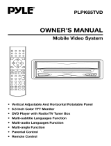
Remote Control
Front Panel Controls
Features What is included?
Troubleshooting
Troubleshooting, cont.
BV9200 User’s Manual - page 3
BV9200 User’s Manual - page 4
BV9200 User’s Manual - page 5
BV9200 User’s Manual - page 6 BV9200 User’s Manual - page 7
BV9200 User’s Manual - page 17 BV9200 User’s Manual - page 18
BV9200 User’s Manual - page 19
BV9200 User’s Manual - page 20
Video quality settings
BV9200 User’s Manual - page 9
DVD or CD Changer Control
Setup Menu structure
BV9200 User’s Manual - page 10
BV9200 User’s Manual - page 8
System wiring: Audio connections in an amplified system
BV9200 User’s Manual - page 12
System wiring: Speaker connections
BV9200 User’s Manual - page 11
System wiring: Power and antenna connections
BV9200 User’s Manual - page 13
System wiring: Connections to a Multi-Disc Changer (optional)
BV9200 User’s Manual - page 14
System wiring: Auxiliary video input connections
BV9200 User’s Manual - page 15
System wiring: Auxiliary video output connections
BV9200 User’s Manual - page 16
System wiring: TV Antenna connections
BV9200 User’s Manual - page 2
General precautions
Safety precautions
When first unpacking your new
BV9200, please check first that the
package contains all of the items
below. If something is missing, contact
the store where you purchased it.
• BV9200 Multi-media disc receiver
• Remote control
• Battery (for remote)
If you experience operation or performance problems with this product, compare your
installation with the electrical wiring diagram on the previous page. If problems persist,
read the following troubleshooting tips which may help eliminate the problems.
Display color is
light or pale.
Display color is incorrectly
adjusted.
Adjust Color and Tint controls.
Video image is
poor when other
video source is
connected.
NTSC/PAL setting is
incorrect.
Set the NTSC/PAL setting
properly according to the other
video source.
Disc cannot be
played, and the
display reads
“Parental Violation.”
Viewing has been
restricted by the unit’s
Parental Control settings.
Release the restriction or
change the Parental Control
setting. See the section of this
menu about DVD playback
setup for help.
Disc cannot be
played, and the
display reads
“Parental Violation.”
Viewing has been
restricted by the unit’s
Parental Control settings.
Release the restriction or
change the Parental Control
setting. See the section of this
menu about DVD playback
setup for help.
DVD pauses
during playback.
The disc is a dual-layer
DVD disc.
It is normal for dual-layer discs
to pause during playback briefly
and then resume playback.
• This disc player is a Class 1 Laser
Product. It uses a visible/invisible laser
beam that could cause hazardous
radiation if exposed directly to the
consumer. Use of controls,
adjustments, or procedures other than
those specified in this manual may
result in hazardous radiation exposure.
• Do not open or attempt to repair
this unit yourself. Refer any repairs to
a qualified service technician.
• Be sure that the volume level of the
player does not interfere with the
driver’s hearing. The driver must be
aware and be able to react to sound
outside the vehicle.
• This product should not be used
with an installed video screen which
is visible to the driver of the vehicle.
• In some states and countries, the
viewing of images on a screeen inside
a vehicle is illegal, even by people
other than the driver. Be sure that the
installation and operation of this
system is in compliance with local
rules and regulations.
All specifications subject to change without notice.
13.8V
4.0 amperes
7.00” x 3.98” x 6.02” (178 x 101 x 153mm)
DVD-Video, Audio CD, Video CD, MP3 CD
CD, CD-R, CD-RW, DVD+R, DVD-R, DVD+RW, DVD-RW
20Hz-20kHz
greater than 70dB
DVD PLAYER
Playable disc formats
Playable disc types
Frequency response
Signal-to-noise ratio
6.5-inch wide format (143.4 x 79.33mm)
TFT active matrix LCD
1440 x 234 pixels
NTSC, PAL, SECAM
MONITOR
Screen size
Display type
Resolution
Color system
87.5MHz - 108MHz
107MHz
greater than 60dB
40dB
FM TUNER
Tuning range
Intermediate freq.
Signal-to-noise ratio
Stereo separation
530kHz-1620kHz (9kHz)
450kHz
33dB or lower
AM TUNER
Tuning range
Intermediate freq.
Usable sensitivity
NTSC, PAL, SECAM
VHF Channels 2-13, UHF Channels 14-69 NTSC-M
75 ohm 4 Channel diversity
TV TUNER
Color system
Channel range
Antenna input type
80W x 4 channels
4 - 8 ohms
AUDIO AMPLIFIER
Power output, max.
Speaker impedance
GENERAL
Input voltage
Current consumption
Dimensions
SYMPTOM CAUSE REMEDY
GENERAL PROBLEMS
SYMPTOM CAUSE REMEDY
LCD SCREEN PROBLEMS
SYMPTOM CAUSE REMEDY
DISC PROBLEMS
SYMPTOM CAUSE REMEDY
DVD PLAYBACK PROBLEMS
SYMPTOM CAUSE REMEDY
MP3 PLAYBACK PROBLEMS
AMS/RPT BUTTON
In Radio Mode, pressing this button allows
you to sequentially browse the preset
radio stations.
In TV mode, press this button to change
the soundtrack mode. Press and hold for
3 seconds to automatically scan and store
stations.
10
TITLE
In DVD Mode, pressing this button takes
you to the Title menu for the currently
playing disc.
11
PBC (Playback Mode)
In VCD Mode, pressing this button takes
you the VCD Playback Control menu.
Within this menu, use the number
buttons to choose the songs you wish
to hear.
12
UP/DOWN/LEFT/RIGHT ARROWS
In DVD Mode, these buttons are used to
navigate the menus to make various
system settings. When done, press
ENTER to confirm.
13
ENTER
In DVD Mode, this button is used to
confirm a setting within the on-screen
menu system.
14
OSD
Press this button to display the title,
chapter, playing time and elapsed time
for the current disc.
15
BAND
This button is used in the Radio and
DVD/VCD modes. It has different
functions in the two modes:
In Radio mode, a SHORT press of this
button will cause the unit to advance
among the bands available in the
following sequence:
In DVD/VCD mode, pressing this button
will cause the unit to advance to through
the different video output modes in this
sequence:
AUTO SELECT > PAL > NTSC
16
LOC/RDM (Local/Distant, Random)
In Radio mode, this button is used to
select between Local (LOC) and Distant
radio reception modes.
In DVD, VCD, CD or MP3 modes,
pressing this button will cause the
tracks or titles on the disc to play in
random order.
17
ST/PROG (Mono/stereo, Program)
In Radio mode, this button is used to
select between Mono and Stereo radio
reception modes. If reception of a stereo
station is poor, sometimes it can be
improved by switching to mono reception.
In DVD, VCD, CD or MP3 modes, this
button acts as a STOP button when in
one of the programmed playback modes
such as Random, Repeat, etc.
18
STOP
Pressing this button will stop disc
playback.
19
PLAY/PAUSE
Press of this button to begin playback of
the disc. A second short press will pause
the playback.
20
GO TO
When you are in playback mode, pressing
this button opens a menu which allows
you to insert a particular time in a program.
When you press ENTER, playback begins
from the start time you entered.
21
SUBTITLE
Pressing this button will allow you to
change the subtitles on a DVD disc.
22
NOTE: This function is only available in DVD discs which support it.
ANGLE
If your DVD disc supports different viewing
angles of the program content, pressing
this button will enable you to change the
viewing angle.
24
AUDIO
If your DVD disc supports different audio
output formats, languages or setups,
pressing this disc will enable you to change
it by pressing this button.
23
SLOW
Press this button repeatedly to reduce
the speed of playback until desired speed
is selected:
Forward 1/2X > 1/4X > 1/8X > 1/16X > Normal >
Reverse 1/2X > 1/4X > 1/8X 1/16X
25
SETUP
Pressing this button opens up the SETUP
menu, which permits you to make various
system settings (described on page 9).
26
ZOOM
If your DVD disc supports zooming into
the image, pressing this button will provide
this function.
24
If you wish to adjust some of the video display quality settings (including menu language),
press and hold the SELECT button on the front panel for 3-5 seconds. You will see a
display with the following information:
Press the SELECT button until the item you wish to change has been highlighted. The
current setting is shown to the right of the bar graph. Use the UP and DOWN buttons
to change the setting to the way you like. Press SELECT to save and move the cursor.
when you are done, wait a few moments and the screen will return to normal mode.
If you have attached this unit to a compatible CD changer, press the MODE switch on
the front panel until you have selected CDC mode.
All functions are similar to regular CD audio mode, except you can now switch between
discs in your changer by using the two buttons in the lower right corner of the front
panel as Disc Select UP and Disc Select DOWN buttons.
Pressing the SETUP button on either the front panel or the remote to access the Setup
Menu. To navigate the menu structure, use the LEFT, RIGHT, UP and DOWN ARROW
buttons. Use the ENTER button to save a new setting.
The Setup Menu is structured as follows:
If you are using the BV9200 in a mobile A/V system which includes a power amplifier
and speakers, connect the
If you are using the BV9200 in a mobile system which does not include an audio amplifier
(so you are using the internal amplifier in the BV9200), connect the speakers to the
wiring connector provided as shown in the drawing below.
Make power and antenna connections as shown in the diagram below.
If you are using additional optional equipment, such as a rear view camera and/or a car
amplifier, be sure to also connect the orange and/or blue wires, respectively, as shown.
The BV9200 has internal circuitry to permit it to be used to control an external CD
changer, such as the BOSS Model CDC3000A or similar compatible models. If you are
considering adding a CD changer to your system, please call BOSS Audio technical
support to get advice about which changers are compatible with the BV9200.
If you are using the BV9200 in a mobile system which does not include an audio amplifier
(so you are using the internal amplifier in the BV9200), connect the speakers to the
wiring connector provided as shown in the drawing below.
If you have an other video monitor(s) in your vehicle that you wish to display the program
playing in the BV9200, connect the monitor as shown in the diagram below. If there is
more than one such monitor, you will need to add a video splitter or a multi-channel
video signal amplifier to the system as well. Please consult with your dealer for assistance
in purchasing these.
To watch TV in a vehicle usually requires connecting an antenna system to the tuner
unit (built-in to the BV9200). Connect high quality antennas as shown in the diagram
below. Depending on the type of antenna system you are using, you will connect to
either the single RCA connector or the two 3.5mm jscks (for a diversity antenna system).
To REAR Audio Inputs of
amplifier
To FRONT Audio Inputs
of amplifier
LEFT REAR
AUDIO OUT
(GREY CABLE
with WHITE JACK)
RIGHT REAR
AUDIO OUT
(GREY CABLE
with RED JACK)
LEFT REAR
AUDIO OUT
(GREY CABLE
with WHITE JACK)
RIGHT FRONT
AUDIO OUT
(GREY CABLE
with RED JACK)
to REMOTE
power terminal
8-pin
DIN-type
Connector
Multi-Disc Disc Changer
GREY CABLE
with
WHITE JACK
Video input from
DVD Changer
Video Output from
DVD Changer
NOTE:
Video input connection is only
necessary if changer is DVD or VCD
format. CD Changers do not require
this connection.
RIGHT REAR
Speaker
RIGHT FRONT
Speaker
CHOKE
WITH
FUSE HOLDER
Optional EXTERNAL POWER
AMPLIFIER
If not present, BLUE wire is left
unconnected.
Optional REAR CAMERA
control switch connnection
If not present, ORANGE wire is left
unconnected.
to Ignition Switch
(ACC+)
to Reverse (Backup)
Light Switch (+)
(do not connect to camera,
shown only as example)
REAR-VIEW
CAMERA
(CCD IN)
GREY Cable
with
WHITE Jack
GREY Cable
with
WHITE Jack
AUXILIARY VIDEO SOURCE
(e.g. Video Game)
(AUX IN)
GREY Cable
with
YELLOW Jack
Video Input
Cable
Diversity antenna
system
GREY Cable
with
WHITE Jack
GPS NAVIGATION UNIT
(GPS
Video IN)