Safety Precautions
FOR USA AND CANADA
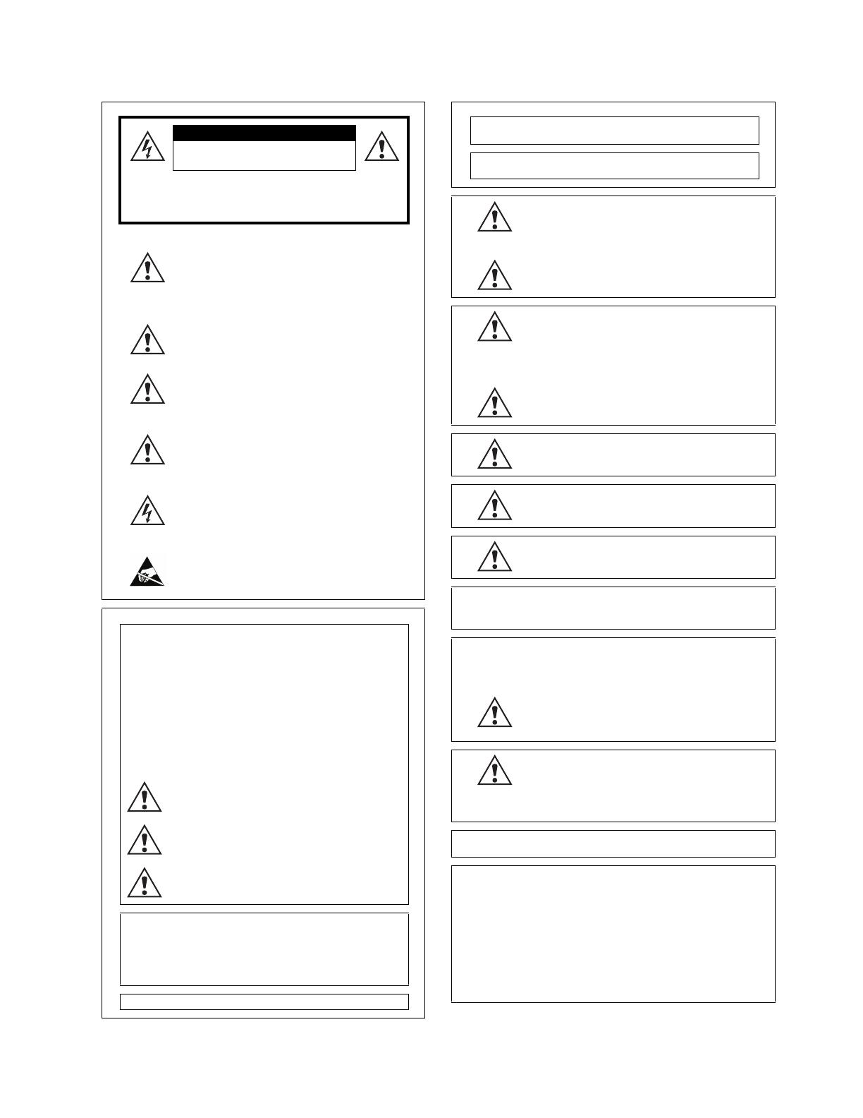
CAUTION
RISK OF ELECTRIC SHOCK
DO NOT OPEN
CAUTION: TO REDUCE THE RISK OF ELECTRIC SHOCK, DO
NOT REMOVE COVER (OR BACK).
NO USER-SERVICEABLE PARTS INSIDE. REFER
SERVICING TO QUALIFIED SERVICE PERSONNEL.
Symbol Meanings:
This symbol on the equipment refers you to
important operating and maintenance (servicing)
instructions within the Product Manual
Documentation. Failure to heed this information may
present a major risk of damage or injury to persons
or equipment.
Warning -The symbol with the word "Warning"
within the equipment manual indicates a potentially
hazardous situation, which if not avoided, could
result in death or serious injury.
Caution - The symbol with the word "Caution" within
the equipment manual indicates a potentially
hazardous situation, which if not avoided, may result
in minor or moderate injury. It may also be used to
alert against unsafe practices.
Notice - The symbol with the word "Notice" within
the equipment manual indicates a situation, which if
not avoided, may result in major or minor equipment
damage or a situation, which could place the
equipment in a non-compliant operating state.
Warning Hazardous Voltages - This symbol is
intended to alert the user to the presence of
uninsulated "dangerous voltage" within the product
enclosure that may be of sufficient magnitude to
constitute a risk of shock to persons.
ESD Susceptibility - This symbol is used to alert the
user that an electrical or electronic device or
assembly is susceptible to damage from an ESD
event.
US
FCC Part 15 Subpart B
This equipment has been tested and found to comply with the
limits for a class A Digital device, pursuant to part 15 of the FCC
Rules. These limits are designed to provide reasonable
protection against harmful interference when the equipment is
operated in a commercial environment. This equipment
generates, uses, and can radiate radio frequency energy and, if
not installed and used in accordance with the instruction manual,
may cause harmful interference to radio communications.
Operation of this equipment in a residential area is likely to cause
harmful interference in which case the user will be required to
correct the interference at his own expense.
Notice - Changes or modifications to this equipment
not expressly approved by JVC could void the user's
authority to operate this equipment.
Notice - The rating plate (serial number plate) is on
this unit.
WARNING - TO REDUCE THE RISK OF FIRE OR
ELECTRIC SHOCK, DO NOT EXPOSE THIS
APPLIANCE TO RAIN OR MOISTURE.
THIS DEVICE COMPLIES WITH PART 15 OF THE FCC
RULES. OPERATION IS SUBJECT TO THE FOLLOWING TWO
CONDITIONS: (1) THIS DEVICE MAY NOT CAUSE HARMFUL
INTERFERENCE, AND (2) THIS DEVICE MUST ACCEPT ANY
INTERFERENCE RECEIVED, INCLUDING INTERFERENCE
THAT MAY CAUSE UNDESIRED OPERATION.
This unit should be used with 12 V DC only.
CANADA
This Class "A" digital apparatus complies with Canadian
ICES-003.
Cet appareil numerique de la classe "A" est conforme a la norme
NMB-003 du Canada.
WARNING - TO REDUCE THE RISK OF FIRE OR
ELECTRIC SHOCK, DO NOT EXPOSE THIS
APPLIANCE TO RAIN OR MOISTURE.
This unit should be used with 12V DC only.
CAUTION - To prevent electric shocks and fire
hazards, do NOT use any other power source.
AVERTISSEMENT - POUR EVITER LES RISQUES
D'INCENDIE OU D'ELECTROCUTION, NE PAS
EXPOSER L'APPAREIL A L'HUMIDITE OU A LA
PLUIE.
Ce magnétoscope ne doit être utilizé que sur du courant direct en
12V.
ATTENTION - Afin d'eviter tout resque d'incendie ou
d'electrocution, ne pas utiliser d'autres sources
d'alimentation électrique.
Notice - The rating plate (serial number plate) is on
this unit.
REMARQUE - Le plaque signalétique (plaque du
numéro desérie) es située sur le cadre intérieur de
l'unité.
CAUTION - To prevent electric shock, do not open
the cabinet. No user serviceable parts inside. Refer
servicing to qualified service personnel.
EUROPE
This equipment is in compliance with the essential requirements
and other relevant provisions of CE Directive 93/68/EEC.
INTERNATIONAL
This equipment has been tested to CISPR 22:1997 along with
amendments A1:2000 and A2:2002 and found to comply with the
limits for a Class A Digital device.
Notice - This is a Class A product. In domestic
environments this product may cause radio
interference in which case the user may have to take
adequate measures.
CAUTION - Where there are strong electromagnetic
waves or magnetism, for example near a radio or TV
transmitter, transformer, motor, etc., the picture and
the sound may be disturbed. In such cases, please
keep the apparatus away from the sources of the
disturbance.
Due to design modifications, data given in this instruction book
are subject to possible change without prior notice.
Dear Customer,
This apparatus is in conformance with the valid European
directives and standards regarding electromagnetic compatibility
and electrical safety.
European representative of Victor Company of Japan, Limited is:
JVC Technical Services Europe GmbH
Postfach 10 05 04
61145 Friedberg
Germany


