Frigidaire 137153100A (0903) User manual
- Category
- Washing machines
- Type
- User manual
This manual is also suitable for

Installation Instructions
Washer
Instructions d’Installation
Laveuse
P/N 137153100A (0903)
Printed in U.S.A.

Important Safety Instructions
Recognize safety symbols, words and labels
Safety items throughout this manual are labeled with a
WARNING or CAUTION based on the risk type as described:
Destroy the carton and plastic bags after the dryer is un-•
packed. Children might use them for play. Cartons covered
with rugs, bedspreads, or plastic sheets can become airtight
chambers causing suffocation. Place all materials in a gar-
bage container or make materials inaccessible to children.
The electrical service to the washer must conform with local •
codes and ordinances and the latest edition of the National
Electrical Code, ANSI/NFPA 70, or in Canada, CSA 22.1
Canadian Electrical Code Part 1.
To avoid back or other injury, have more than one person •
move or lift the washer.
The instructions in this manual and all other literature in-•
cluded with this dryer are not meant to cover every possible
condition and situation that may occur. Good safe practice
and caution MUST be applied when installing, operating
and maintaining any appliance.
Save these instructions
for future reference.
This symbol alerts you to situations that
may cause serious body harm, death or
property damage.
This symbol alerts you to situations that may
cause bodily injury or property damage.
For your safety the information in this manual must be followed to minimize the risk of fi re or explosion or to
prevent property damage, personal injury or loss of life. Do not store or use gasoline or other fl ammable vapors and liquids in
the vicinity of this or any other appliance.
2
Important Safety Instructions ................................................2
Installation Requirements .................................................. 2-3
Installed Dimensions .............................................................4
Unpacking Instructions ..........................................................4
Installation Instructions ..................................................... 5-6
Replacement parts ................................................................6
Français ................................................................................7
Tools needed for installation:
3/8” socket and ratchet•
Adjustable pliers•
Carpenter’s level•
Table of Contents
CIRCUIT - Individual, properly polarized and grounded 15
amp. branch circuit fused with 15 amp. time delay fuse or
circuit breaker.
POWER SUPPLY - 2-wire, with ground, 120 volt single phase,
60 Hz, Alternating Current.
OUTLET RECEPTACLE - Properly grounded 3-prong receptacle
to be located so the power supply cord is accessible when
the washer is in an installed position.
Because of potentially inconsistent voltage capabili-
ties, the use of this washer with power created by gas pow-
ered generators, solar powered generators, wind powered
generators or any other generator other than the local utility
company is not recommended.
GFI (Ground Fault Interrupter) receptacle is not re-
quired.
Read all of the following instructions before
installing and using this appliance:
type
type
Grounding
Grounding
receptacle
receptacle
wa
wa
ll
ll
Po
Po
wer cord
wer cord
with 3-prong
with 3-prong
gr
gr
ounded plug
ounded plug
Do not, under any circumstances,
Do not, under any circumstances,
cut, remove, or bypass the
cut, remove, or bypass the
grounding prong.
grounding prong.
The washer MUST be grounded. In the event of malfunction 1.
or breakdown, grounding will reduce the risk of electrical
shock by a path of least resistance for electrical current.
Since your washer is equipped with a power supply cord 2.
having an equipment-grounding conductor and a grounding
plug, the plug MUST be plugged into an appropriate,
copper wired receptacle that is properly installed and
grounded in accordance with all local codes and ordinances
or in the absence of local codes, with the National Electrical
Codes, ANSI/NFPA 70 (latest edition). If in doubt, call a
licensed electrician. DO NOT cut off or alter the grounding
prong on the power supply cord. In situations where a
two-slot receptacle is present, it is the owner’s responsibility
to have a licensed electrician replace it with a properly
grounded three prong grounding type receptacle.
Electrical system requirements
Grounding requirements
- ELECTRICAL SHOCK HAZARD - Improper
connection of the equipment grounding conductor can result
in a risk of electrical shock. Check with a licensed electrician
if you are in doubt as to whether the appliance is properly
grounded.
Installation Requirements

3
For installations requiring a longer drain hose, have a
qualifi ed technician install a longer drain hose (according to
your model number) available from an authorized parts dis-
tributor. For drain systems in the fl oor, install a syphon break
kit available from your local hardware store.
96”
(244cm)
max.
33”
(84cm)
min.
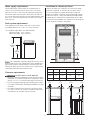
Drain system requirements
Drain capable of eliminating 17 gals (64.3 L) per minute.
A standpipe diameter of 1-1/4 in. (3.18 cm) minimum.
The standpipe height above the fl oor should be:
Minimum height: 33 in. (84 cm)
Maximum height: 96 in. (244 cm)
Water supply requirements
Hot and cold water faucets MUST be installed within 42
inches (107 cm) of your washer’s water inlet. The faucets
MUST be 3/4 inch (1.9 cm) with threading for laundry hose
connection. Water pressure MUST be between 30 and 120
psi. Pressure difference between hot and cold cannot be more
than 10 psi. Your water department can advise you of your
water pressure.
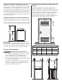
Clearance requirements
60 sq. in.
(387.1cm²)
3”
(7.6cm)
60 sq. in.
(387.1cm²)
3”
(7.6cm)
closet door
Installation in a Recess or Closet
If washer and dryer are installed in the same closet, door
ventilation is required: A minimum of 120 square inches
(774.2 cm²) of opening, equally divided at the top and
bottom of the door, is required. Louvered openings should
be located 3 inches (7.6 cm) from bottom and top of door.
Air openings are required to be unobstructed when a door
is installed. A louvered door with equivalent air openings for
the full length of the door is acceptable.
DO NOT INSTALL YOUR WASHER:
In an area exposed to dripping water or outside weather 1.
conditions. The ambient temperature should never be be-
low 60° F (15.6° C) to maximize detergent effectiveness
In an area (garage or garage-type building) where gaso-2.
line or other fl ammables (including automobiles) are kept
or stored.
On carpet. Floor MUST be solid with a maximum slope 3.
of 1 inch (2.54 cm). To minimize vibration or movement,
reinforcement of the fl oor may be necessary.
0”
(0 cm)
0”
(0 cm)
1”
(2.5 cm)
0”
(0 cm)
16”
(40.5 cm)
MINIMUM INSTALLATION CLEARANCES - Inches (cm)
SIDES REAR TOP FRONT
Alcove 0” (0 cm) 0” (0 cm) 16” (40.5 cm) n/a
Under-
Counter
n/a n/a n/a n/a
Closet 0” (0 cm) 0” (0 cm) 16” (40.5 cm) 1” (2.5 cm)

4
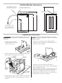
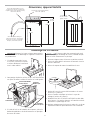
Installed Washer Dimensions
Unpacking Instructions
27” (68.6 cm)27” (68.6 cm)
36”
(91.5 cm)
24”
(61 cm)
43 5/8”
(111 cm)
power cord length on rear of
washer approximately 59” (150 cm)
51” (129.5 cm)
to clear open lid
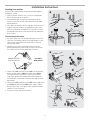
If the washer is to be transported at a later date,
the tub blocking pad, shipping bolt, and plastic spacer block
should be retained.
To prevent vibration, possible machine dam-
age and maximize performance, the following steps must be
completed.
If foam tub block has been 1.
removed, reinsert it now and
retape the lid securely.
Using a rug, blanket or piece of cardboard to protect the 2.
fl oor, carefully lay the washer on its left side.
Using a ratchet with 3/8” socket, remove the mechanism 3.
shipping bolt and plastic spacer block from the center of
the base.
Carefully return the washer to an upright position.4.
Remove the tape holding the lid shut and open the lid.5.
Remove the foam tub block.6.
Remove the inlet hoses and other tub contents.7.
From the back of the washer, remove the wire shipping 8.
clip securing the drain hose.
DO NOT remove the PLASTIC CLAMP which secures the 9.
drain hose to the right side of the washer backsheet. It
helps form a standpipe to prevent water siphoning.
Carefully move the washer to within 4 feet of the fi nal 10.
location for the start of the installation.
water supply connection on
rear of washer, inlet hose length
approximately 43” (109 cm)
drain hose retention clamp
on rear of washer, loose
hose length beyond clamp
approximately 54” (137 cm)
WIRE CLIP
PLASTIC
SPACER
SHIPPING
BOLT
PLASTIC
CLIP

5
a
b
c
d
raise
lower
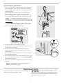
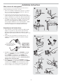
Leveling your washer
Excessive noise and vibration can be prevented by properly
leveling the washer.
With the washer within 4 feet (1 m) of its fi nal location, 1.
place a level on top of the washer.
Use adjustable pliers to adjust the leveling legs so the 2.
washer is level front-to-rear and side-to-side, and stable
corner-to-corner.
Press down on alternate corners and sides and feel for the 3.
slightest movement. Adjust the appropriate leg(s) so the
washer sits solidly on the fl oor on ALL four legs. Keep the
leveling leg extension at a minimum for best performance
of the washer.
Run some water from the hot and cold faucets to fl ush the 1.
water lines and remove particles that might clog the water
valve screens and to determine which faucet is hot and
which is cold supply.
Remove the inlet hoses and rubber washers from the 2.
plastic bag located in the drum of the washer and install
the rubber washers in each end of the inlet hoses.
Connecting inlet water
Connect the 3. HOT inlet hose to the HOT inlet connection
on the washer and the COLD inlet hose to the COLD
inlet connection on the washer. Tighten by hand until
snug. Then tighten each supply connection another 2/3
turn with pliers. Do not cross thread or over-tighten these
connections.
Connect the 4. HOT inlet hose to the HOT water supply and
the COLD inlet hose to the COLD water supply. Tighten
by hand until snug. Then tighten each supply connection
another 2/3 turn with pliers.
Turn on the water and check for leaks.5.
RUBBER WASHERS
MUST BE PRESENT
USE ONLY
NEW HOSES
Installation Instructions
a
e
f
g
b
c
d
“C”
(COLD)
“H”
(HOT)

6
Grounding type
Grounding type
wa
wa
ll receptacl
ll receptacle
Po
Po
wer cord with
wer cord with
3-prong
3-prong
gr
gr
ounded plug
ounded plug
Do not,
Do not,
under
under
an
an
y cir
y cir
cumstances,
cumstances,
cut,
cut,
remo
remo
ve
ve,
or b
or b
ypass th
ypass the
gr
gr
ounding pr
ounding pr
ong.
ong.
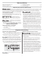
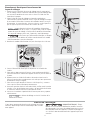
CABLE TIE
Connecting drain and electrical
Form a “U” shape on the end of the drain hose with the hose 1.
pointed toward the drain. Place the formed end in a laundry
tub or a standpipe and secure with a cable tie provided in the
enclosure package.
Place the hook end of the drain hose in the drain opening. 2.
Secure the drain hose with the cable tie (provided in the
enclosure package) to the standpipe, inlet hose, laundry tub,
etc. so the hose does not pull out from the force of the water.
Plug the power cord into a grounded outlet.3.
Turn on the power at circuit breaker/fuse box.4.
Carefully slide the washer to its fi nal position. Recheck for level 5.
and rock corners for stability.
Read the Use & Care Guide provided with the washer. It 6.
contains valuable and helpful information that will save you
time and money.
Run the washer through a complete cycle, checking for water 7.
leaks and proper operation.
If you have any questions during initial operation, please review 8.
the “Service Prevention Checklist” in your Use & Care Guide
before calling for service.
Place these instructions in a location near the washer for future 9.
reference.
A wiring diagram and technical data sheet are
located inside the washer console.
Replacement parts:
If replacements parts are needed for your washer, contact the
source where you purchased your washer.
- ELECTRICAL SHOCK HAZARD - Label all
wires prior to disconnection when servicing controls. Wiring
errors can cause improper and dangerous operation. Verify
proper operation after servicing.
Check to ensure the power is off at circuit
breaker/fuse box before plugging the power cord into outlet.
The standpipe inside diameter must be 1-1/4” (3.2
cm) minimum. There must be an air gap around the drain hose
in the standpipe. A snug hose fi t can cause a siphoning action.
Page is loading ...
Page is loading ...
Page is loading ...
Page is loading ...
Page is loading ...
Page is loading ...
-
 1
1
-
 2
2
-
 3
3
-
 4
4
-
 5
5
-
 6
6
-
 7
7
-
 8
8
-
 9
9
-
 10
10
-
 11
11
-
 12
12


Frigidaire 137153100A (0903) User manual
- Category
- Washing machines
- Type
- User manual
- This manual is also suitable for
Ask a question and I''ll find the answer in the document
Finding information in a document is now easier with AI
in other languages
Related papers
-
Frigidaire FFTW4120SW Wiring Diagram/Installation Instructions
-
-
-
Frigidaire FFTW1001PW Installation guide
-
Frigidaire 137168200A User manual
-
Frigidaire FAHE2022MW Installation guide
-
-
Frigidaire FFLE2022MW Installation guide
-
-
Frigidaire FFLE3911QW Installation guide
Other documents
-
Kenmore 137630800 Installation guide
-
-
Electrolux EFLS617SIW Installation guide
-
Electrolux EFLS517SIW Installation guide
-
Electrolux EFLW317TIW Installation guide
-
Electrolux EFLS210TIW Installation guide
-
Electrolux EIFLS55IIW Installation guide
-
Kenmore 41761712511 Installation guide
-
Electrolux EFLW317TIW User manual
-
Electrolux 137064300 B User manual