Blue Rhino 235000 User manual
- Category
- Barbecues & grills
- Type
- User manual
This manual is also suitable for

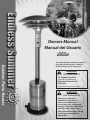
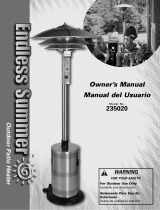
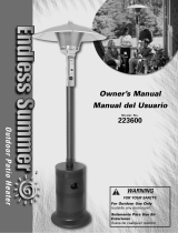
Owners Manual
Manual del Usuario
Model No.
235000
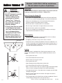
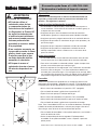
WARNING
FOR YOUR SAFETY
For Outdoor Use Only
(Outside any enclosure)
Solamente Para Uso En
Exteriores
(Fuera de cual quier recinto)
WARNING
FOR YOUR SAFETY
Improper installation,
adjustment, alteration,
service or maintenance
can cause injury or property
damage. Read the installation,
operation and maintenance
instructions thoroughly before
installing or servicing this
equipment.
U.S. Patent Number: 6,6102,031; 6,470,877;
Hong Kong Patent Number: 1108587.1;
All Other Foreign Patents May Apply.

Contact 1-800-762-1142 for assistance.
Do not return to place of purchase.
®
Owner’s manual: model 235000 outdoor patio heater 6/11/04
1
Contact 1-800-762-1142 for assistance.
Do not return to place of purchase.
®
Owner’s manual: model 235000 outdoor patio heater 6/11/04
2
WARNING
FOR YOUR SAFETY
For Outdoor Use Only
(Outside any enclosure)
WARNING
FOR YOUR SAFETY
1. Gas leaks may cause a re or
explosion which can cause
serious bodily injury or death,
or damage to property.
2. You must follow all leak
checking procedures as
outlined in step 13 before
operating this unit.
3. Never use an open ame to
check for leaks.
WARNING
FOR YOUR SAFETY
Do not store or use gasoline
or other ammable vapors or
liquids in the vicinity of this or
any other appliance.
WARNING
FOR YOUR SAFETY
Improper installation,
adjustment, alteration, service
or maintenance can cause
injury or property damage.
Read the installation, operation
and maintenance instructions
thoroughly before installing or
servicing this equipment
WARNING
California Proposition 65:
Chemicals known to the state of
California to cause cancer, birth
defects, or other reproductive
harm are created by the
combustion of propane.
WARNING
FOR YOUR SAFETY
• Purchaser assumes all risk in
the assembly and operation
of this unit. Failure to follow
this manual’s WARNINGs
and instructions can result in
severe personal injury, death
or property damage.
• Do not use in an explosive
atmosphere. Keep heater away
from areas where ammable
liquids, gasoline, vapors, or
explosives are stored or used.
WARNING
FOR YOUR SAFETY
If you smell gas:
1. Shut off gas to the appliance.
2. Extinguish any open ame.
3. If odor continues, immediately
call your gas supplier.

Contact 1-800-762-1142 for assistance.
Do not return to place of purchase.
®
Owner’s manual: model 235000 outdoor patio heater 6/11/04
1
Contact 1-800-762-1142 for assistance.
Do not return to place of purchase.
®
Owner’s manual: model 235000 outdoor patio heater 6/11/04
2
Table of Contents
Safety First! . . . . . . . . . . . . . . . . . . . . . . . . . . . . . . . . . . . . . . . . . . . . . . . . . . . . .3
Assembly Instructions
Components & Hardware . . . . . . . . . . . . . . . . . . . . . . . . . . . . . . . . . . . . . .5
General Components & Features . . . . . . . . . . . . . . . . . . . . . . . . . . . . . . . .6
Additional Requirements . . . . . . . . . . . . . . . . . . . . . . . . . . . . . . . . . . . . . .6
Step 1 Wheel Assembly to Base . . . . . . . . . . . . . . . . . . . . . . . . . . . . . . .6
Step 2 Attach Legs to Base . . . . . . . . . . . . . . . . . . . . . . . . . . . . . . . . . . .7
Step 3 Attach Platform to Legs . . . . . . . . . . . . . . . . . . . . . . . . . . . . . . . .7
Step 4 Attach Weight Plate to Base . . . . . . . . . . . . . . . . . . . . . . . . . . . . .8
Step 5 Insert Gas Line Through Platform / Attach Shroud Cover . . . . . .8
Step 6 Attach Small and Medium Domes to Engine . . . . . . . . . . . . . . . .9
Step 7 Attach Engine to Post . . . . . . . . . . . . . . . . . . . . . . . . . . . . . . . . . .9
Step 8 Attach Engine/Post to Platform . . . . . . . . . . . . . . . . . . . . . . . . . . 9
Step 9 Connect Gas Line to Engine . . . . . . . . . . . . . . . . . . . . . . . . . . . .10
Step 10 Attach Top Dome to Emitter . . . . . . . . . . . . . . . . . . . . . . . . . . .10
Step 11 Secure Gas Line . . . . . . . . . . . . . . . . . . . . . . . . . . . . . . . . . . . .10
Step 12 Connect Gas Line to Cylinder . . . . . . . . . . . . . . . . . . . . . . . . . .11
Step 13 Check for Leaks . . . . . . . . . . . . . . . . . . . . . . . . . . . . . . . . . . . .11
Step 14 Replace Engine Access Panel . . . . . . . . . . . . . . . . . . . . . . . . . .12
Step 15 Install Igniter Battery . . . . . . . . . . . . . . . . . . . . . . . . . . . . . . . . .12
Operation
Before Turning Gas Supply ON . . . . . . . . . . . . . . . . . . . . . . . . . . . . . . . .13
Before Lighting . . . . . . . . . . . . . . . . . . . . . . . . . . . . . . . . . . . . . . . . . . . . .13
Lighting . . . . . . . . . . . . . . . . . . . . . . . . . . . . . . . . . . . . . . . . . . . . . . . . . . 13
Re-Lighting . . . . . . . . . . . . . . . . . . . . . . . . . . . . . . . . . . . . . . . . . . . . . . . .14
Shutdown . . . . . . . . . . . . . . . . . . . . . . . . . . . . . . . . . . . . . . . . . . . . . . . . .14
Operation Checklist . . . . . . . . . . . . . . . . . . . . . . . . . . . . . . . . . . . . . . . . .15
Troubleshooting . . . . . . . . . . . . . . . . . . . . . . . . . . . . . . . . . . . . . . . . . . . . . . . . .16
Maintenance . . . . . . . . . . . . . . . . . . . . . . . . . . . . . . . . . . . . . . . . . . . . . . . . . . .17
Storage . . . . . . . . . . . . . . . . . . . . . . . . . . . . . . . . . . . . . . . . . . . . . . . . . . . . . . .18
Service . . . . . . . . . . . . . . . . . . . . . . . . . . . . . . . . . . . . . . . . . . . . . . . . . . . . . . . .18
Warranty . . . . . . . . . . . . . . . . . . . . . . . . . . . . . . . . . . . . . . . . . . . . . . . . . . . . . .19
Specifications . . . . . . . . . . . . . . . . . . . . . . . . . . . . . . . . . . . . . . . . . . . . . . . . . .20
The use and installation of this product must conform to local codes. In absence
of local codes, us the National Fuel and Gas Code, ANSI Z223, 1/NFPA 54,
Storage and Handling of Liquid Petroleum Gases, ANSI/NFPA 58 or CSA B149.1,
Natural Gas and Propane Installation Code.
Save these instructions
for future reference. If you
are assembling this unit for
someone else, give this
manual to him or her to
save for future reference.

Contact 1-800-762-1142 for assistance.
Do not return to place of purchase.
®
Owner’s manual: model 235000 outdoor patio heater 6/11/04
3
Contact 1-800-762-1142 for assistance.
Do not return to place of purchase.
®
Owner’s manual: model 235000 outdoor patio heater 6/11/04
4
Safety First!
Read and become familiar with this entire manual, especially the following
precautions.
If you are unsure of anything in these instructions, STOP and contact
1-800-762-1142 for assistance.
Caution: This appliance is for outdoor use only (outside any
enclosure). Always make sure there is fresh air ventilation.
• Always maintain at least 36” clearance (top) and 24” clearance (side)
from combustible materials.
• Always place heater on a hard and level surface.
• Do not use if the wind velocity is greater than 10 miles per hour.
• Unit will operate at reduced efficiency below 40ºF (5ºC).
• Keep sprinklers and other water sources away from burner and controls.
• Always use extreme caution when near heater. Alert both children
and adults to the hazards of high temperatures, especially to avoid
burns or clothing catching fire.
• Young children and pets should be carefully supervised when they
are in the area of heater.
• Do not hang clothing or other flammable materials either on or near
heater.
• Any guard or other protective device removed for servicing the
heater must be replaced prior to operating the heater.
• Certain materials or items, when stored under heater, will be subjected
to radiant heat and could be seriously damaged.
• Do not alter heater in any manner.
• The pressure regulator and hose assembly supplied with the appliance
must be used and replacements must be those specified by the
manufacturer.
• Inspect heater before each use. If a damaged part is detected, do not
operate until an original equipment replacement part has been properly
installed. Use of unauthorized parts will void warranty and create an
unsafe condition.
• Do not attempt to use this appliance without a functional factory-
supplied gas regulator in place. If regulator becomes damaged, use only
a factory-supplied replacement.
• Prior to operating heater, replace any guards or protective devices
removed for servicing.
• During operation, do not touch burner assembly. The surface of heater’s
emitter can reach temperatures approaching 1600ºF.
• After shutdown, do not touch burner assembly until heater has cooled
(approximately 45 minutes after use).
Notice: This product should not be used with any fuel other than liquid
propane. Use of other fuels will detract from heaters performance and will
void your warranty.
Before you do anything else,
read and understand all
precautions in Safety First!
WARNING
FOR YOUR SAFETY
• Purchaser assumes all risk in
the assembly and operation
of this unit. Failure to follow
this manual’s WARNINGs
and instructions can result in
severe personal injury, death
or property damage.
• Do not use in an explosive
atmosphere. Keep heater
away from areas where
ammable liquids, gasoline,
vapors, or explosives are
stored or used.
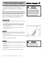
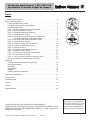
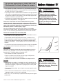
Ceiling
Wall
not light, repeat steps 1-3.
For Complete Shutdown
for outlet pressure of 11 inches water column.
appliance must be used. This regulator is set
The gas pressure regulator provided with this
clearance from the unit to combustible materials:
Depress the gas control knob, turn clockwise to the
"OFF" position. The gas supply must be turned off
at the LP-gas supply cylinder when this applianc
e
For Outdoor Use Only
Pilot
Pilot
Installation on combustible floors with minimum
Rhino
Blue
Improper installation, adjustment, alteration,
property damage . Read installation, operating
and maintenance instructions thoroughly before
service or maintenance can cause injury or
installing or servicing this equipment.
WARNING
CAUTION
is not in use.
Sides - 24", 36" below ceiling
.
ON
ON
Push
Pus
h
Ignitor
Ignito
r
OFF
OFF
(Push in)
Enjoy outdoor living-longer
Endless Summer
knob for 30 seconds until the pilot is
burner should light. If main burner does
3. If the pilot fails to remain lit or
becomes extinguished, repeat steps
4. Turn the gas control knob counter-
clockwise to the "ON" position. Main
Lighting Instructions
1. Close LP gas cylinder valve. Depress
and turn the gas control knob clockwise
to "OFF" position, and wait 5 minutes.
2. Open the cylinder valve and turn the
gas control knob counterclockwise to the
knob). Continue to depress the control
"PILOT" position. Depress the gas control
knob and push ignitor button (located
above and to the right of the control
ignited.
1-2.
24”
36”

Contact 1-800-762-1142 for assistance.
Do not return to place of purchase.
®
Owner’s manual: model 235000 outdoor patio heater 6/11/04
3
Contact 1-800-762-1142 for assistance.
Do not return to place of purchase.
®
Owner’s manual: model 235000 outdoor patio heater 6/11/04
4
Caution: Liquid propane (LP) gas is flammable and hazardous if
handled improperly. Become aware of the characteristics before
using any LP product.
• LP Characteristics – Flammable, explosive under pressure, heavier than
air - settles in pools in low areas.
• In its natural state, propane has no odor. For your safety, an odorant is
added that smells like rotten cabbage.
• Contact with LP can cause freeze burns to skin.
• This heater is shipped from the factory for LP gas use only.
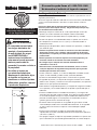
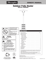
• Use only Department of Transportation (DOT) approved “20 lb.” LP gas
cylinders (same as those commonly used on gas grills) with Acme / Type
1 / QCC safety valves. These valves can be quickly identified because
they have external and internal threads.
• Never use an LP cylinder with a damaged body, valve, collar, or footring.
• Dented or rusted LP cylinders may be hazardous and should be
checked by your LP gas supplier.
• The cylinder supply system must be arranged for vapor withdrawl.
• The cylinder used must include a collar to protect the cylinder valve.
• When heater is not in use, turn LP cylinder OFF.
• Always perform a leak test on gas connections whenever a cylinder
is connected. Never use a flame to test for leaks. Do not smoke while
performing a leak test.
Caution: It is essential to keep the heater’s valve compartment,
burners, and circulating air passages clean.
• Spiders and insects can create a dangerous condition that may damage
heater or make it unsafe. Keep burner area clean of all spiders, webs, or
insects.
• Inspect heater before each use.
• Have heater inspected annually and repairs should be made by a
qualified service person.
• Check heater immediately if any of the following conditions exist:
• The smell of gas in conjunction with extreme yellow tipping of burner
flames.
• Heater does not reach proper temperature.
Note: At temperatures less than 40ºF, heat output will be reduced.
• Heater’s glow is excessively uneven
• Burner makes popping noises during use.
Note: A slight pop is normal when burner is extinguished.
• Carbon deposits may create a fire hazard. Keep dome and emitter clean
at all times.
• Do not clean heater with combustible or corrosive cleaners. Use warm,
soapy water.
• Do not paint engine, engine access panel or dome.
FOR YOUR SAFETY:
Beware of Spiders
Spiders or small insects can get
into the burner tube or other
openings of your heater, and
spin webs or build nests. These
obstructions can lead to gas
ow problems. It is important
to make frequent inspections of
these areas and clean them when
necessary.
Before operating your heater for
the rst time, be sure to check
for obstructions that may have
occurred during shipment.
Need a cylinder or gas?
Try Blue Rhino cylinder exchange service.
It’s easy, fast, safe, and available at tens
of thousands of conveniently located retail
outlets nationwide. You can purchase a
new full cylinder or exchange your empty
for a precision filled one.
For your nearest Blue Rhino retailer visit
www.bluerhino.com.
“20 lb.” LP Cylinder
Collar
Valve
Body
Foot
18”-19”

Contact 1-800-762-1142 for assistance.
Do not return to place of purchase.
®
Owner’s manual: model 235000 outdoor patio heater 6/11/04
5
Contact 1-800-762-1142 for assistance.
Do not return to place of purchase.
®
Owner’s manual: model 235000 outdoor patio heater 6/11/04
6
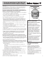
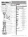
Components
Part Re-order
Name Number
Large Dome . . . . .56-01-309
Medium Dome . . .56-01-257
Small Dome . . . . .56-01-258
Emitter . . . . . . . . .56-01-122
Valve Housing
Assembly . . . . . . .56-01-146
Pilot Assembly . . . 56-01-127
Nozzle . . . . . . . . .56-01-125
Impulse Ignitor . . .56-01-142
Valve Housing
Cover . . . . . . . . . .56-01-145
Knob . . . . . . . . . . 56-01-156
Valve . . . . . . . . . .56-01-304
Pole . . . . . . . . . . .56-01-158
Shroud . . . . . . . . .56-01-164
Platform . . . . . . . .56-01-165
Gas Line/ Regulator
Assembly . . . . . . .56-01-188
Legs (3) . . . . . . . .56-01-193
Wheels . . . . . . . . 56-01-266
Base . . . . . . . . . .56-01-196
Weight Plate . . . . 56-01-198
Hardware
Used in
Picture Qty Description Step(s)
1 Carriage Bolt 4
3/8”-16 x 95 White Zinc Plated
56-01-199
14 Large Bolt 1, 2 & 3
1/4”-20 x 20 Nickel Plated
Hex Head Bolt
56-01-200
6 Small Bolt 6
5/32”-32 x 12 Stainless Steel
Hex Head Bolt
56-01-289
1 Large Screw 3
1/4”-20 x 20 Nickel Plated
Philips Head Screw
56-01-202
4 Small Screw 7
1/4”-20 x 10 Stainless Steel
Philips Head Screw
56-01-203
3 Cap Nut 10
5/26”-18 Stainles Steel Cap Nut
56-01-210
1 Large Nut 4
3/8”-16 Nickel Plated Hex Nut
56-01-208
14 Small Nut 1, 2 & 3
1/4”-20 Nickel Plated Hex Nut
56-01-209
1 Large Lockwasher 4
M10 Nickel Plated Lockwasher
56-01-207
14 Small Lockwasher 1, 2 & 3
M6 Nickel Plated Lockwasher
56-01-206
1 Clip 3
56-01-213
1 Allen Wrench
56-01-215

Contact 1-800-762-1142 for assistance.
Do not return to place of purchase.
®
Owner’s manual: model 235000 outdoor patio heater 6/11/04
5
Contact 1-800-762-1142 for assistance.
Do not return to place of purchase.
®
Owner’s manual: model 235000 outdoor patio heater 6/11/04
6
Assembly Instructions
General Components & Features
Familiarize yourself with all components before proceeding. Refer to page 5 for hardware and components, and page 20
for specifications.
The white ceramic cone in the top of the engine is an important piece. DO NOT REMOVE.
Do NOT attempt assembly unless all components are available. If you believe a component is missing or damaged,
contact 1-800-762-1142 for assistance.
Note: All hardware is mounted on a cardboard pack and numbered to match their assembly step.
Additional Requirements
The following items are not included, but are necessary for the proper assembly of your heater. Do NOT attempt to
assemble without proper tools. A hex (Allen) wrench is necessary and is included in the parts bag.
(1) 7/16” Wrench
(1) 9/16” Wrench
(1) 7/16” Socket Wrench
(1) #2 Phillips Head Screwdriver
(1) Leak Detection Solution (Instructions on how to make solution are included in step 13)
(1) Precision Filled LP Gas Grill Cylinder with Acme Type 1 external threaded valve connection (4-5 gallon size)
Note: You must follow all steps to properly assemble heater.
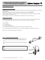
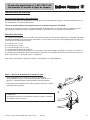
Step 1 – Attach Wheel Assembly to Base
Line up holes in Wheel Bracket with corresponding holes in Base. Insert
2 Large Bolts through holes and 2 Flat Washers, finger tighten 2 small
nuts.
Be sure that the Wheel Assembly is parallel to the base, and fully tighten
bolts.
TIP:
To tighten use a 13 mm wrench on Bolt and a 13mm socket wrench
on Nut.

Contact 1-800-762-1142 for assistance.
Do not return to place of purchase.
®
Owner’s manual: model 235000 outdoor patio heater 6/11/04
7
Contact 1-800-762-1142 for assistance.
Do not return to place of purchase.
®
Owner’s manual: model 235000 outdoor patio heater 6/11/04
8
Step 2 – Attach Legs to Base
Secure Legs to Base using (2) Large Bolts, (2) Small lock washers and
(2) Small nuts per leg. Finger tighten only.
Do not fully tighten until Step 3.
Attach small ‘s’ hook on Cylinder Restraint Chain to left leg.
Step 3 – Attach Platform to Legs
Line up hole in Clip with small threaded hole on bottom of Platform.
Attach Clip loosely to Platform with (1) Large Screw.
Note: Do not tighten until step 11.
Using 7/16” wrench, secure Platform to Legs using (2) Bolts, (2) Small
Lock Washers and (2) Small Nuts per Leg. Tighten fully.
Fully tighten all nuts and bolts from Step 2.
TIP:
To tighten use a 7/16” wrench on Bolt and a 7/16” socket wrench on Nut.

Contact 1-800-762-1142 for assistance.
Do not return to place of purchase.
®
Owner’s manual: model 235000 outdoor patio heater 6/11/04
7
Contact 1-800-762-1142 for assistance.
Do not return to place of purchase.
®
Owner’s manual: model 235000 outdoor patio heater 6/11/04
8
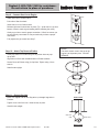
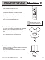
Step 4 – Attach Weight Plate to Base
Lay Base Assembly on its side.
Line up slots at outside edge of Weight Plate with hooks on Wheel
Bracket.
Place Weight Plate in Base, feet out.
Insert Carriage Bolt through center holes of Base and Plate.
Using 9/16” wrench, secure Plate to Base using a (1) Large Lock Washer
and (1) Large Nut.
Place Base Assembly upright.
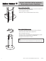
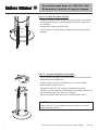
Step 5 – Insert Gas Line through Platform/Attach Shroud Cover
Insert Gas Line up through large hole in Platform from underneath
between center and left leg as shown in illustration.
Slide Shroud Cover over Gas Line, then over Platform/Leg assembly
until bottom of Shroud rests on Base.

Contact 1-800-762-1142 for assistance.
Do not return to place of purchase.
®
Owner’s manual: model 235000 outdoor patio heater 6/11/04
9
Contact 1-800-762-1142 for assistance.
Do not return to place of purchase.
®
Owner’s manual: model 235000 outdoor patio heater 6/11/04
10
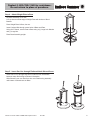
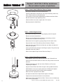
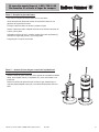
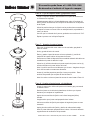
Step 6 – Attach Small & Medium Dome to Engine
Set Engine Assembly on its top as shown at left.
Carefully slide Medium sized Dome over Engine Assembly, and line up
slots in Dome with fins on Dome Brackets.
Line up holes in Dome with threaded holes in Bracket and insert Short
Bolt into each hole, finger tightening at first.
After three bolts are in place, tighten with 7/16” wrench.
Repeat process for Small Dome.
Step 8 – Attach Engine/Post to Platform
Insert Platform Cover over Gas Line and set on top of Shroud Cover.
Insert end of Post without holes over Gas Line, being careful not to bend
Gas Line.
Slide Post through Cover and into collar of Platform so Post rests
completely on Platform.
Align the Control Panel with either the right or left leg attached to base.
Slide Platform Cover up to expose setscrews in Platform and tighten
bottom three setscrews with hex (Allen) wrench supplied.
Make sure Post is perpendicular to Base.
Use top three setscrews to adjust Post’s angle as necessary.
Tighten all six setscrews and slide Cover back down.
Note: Post must be perpendicular to Base. Failure to do so will adversely
affect burner performance.
Step 7 – Attach Engine to Post
Lay Engine Assembly on its side, using shipping carton for support.
Remove and save Control Knob.
Remove and save Engine Access Panel by unscrewing (1) black
Thumbscrew from bottom of Access Door.
Disconnect wire from Igniter by gently pulling wire from back of box.
Align (4) holes in top of Post with (4) holes in bottom of Engine.
Note: One hole is at a different level than the rest. Make sure that all 4
holes line up properly.
Insert (4) Small Screws enough to hold Engine in place. They will be fully
tightened at the end of Step 9.
Note: Do not replace Engine Access Panel until Step 14.

Contact 1-800-762-1142 for assistance.
Do not return to place of purchase.
®
Owner’s manual: model 235000 outdoor patio heater 6/11/04
9
Contact 1-800-762-1142 for assistance.
Do not return to place of purchase.
®
Owner’s manual: model 235000 outdoor patio heater 6/11/04
10
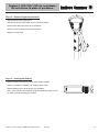
Step 9 – Connect Gas Line to Engine
Attach Gas Line to Control Valve:
Pull collar of Gas Line back.
Insert Gas Line over Control Valve.
Release collar and it should lock in place. (Tip – push Gas Line up from
bottom of Post to make a good seating before releasing the collar.)
Gently tug on line to test for proper connection. If Gas Line moves you
are not properly connected. Do not proceed until you have a proper
connection.
Fully tighten the (4) screws from Step 7.
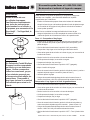
Step 10 – Attach Top Dome to Emitter
Gently lay Heater on its side using one styrofoam insert to prop
up top half.
Align holes in Dome with threaded studs in Emitter brackets.
Secure Dome to Emitter using (3) Cap Nuts. Tighten using 13 mm
wrench.
Stand heater upright.
NOTE:
The white ceramic cone in the top of the
engine is an important piece. DO NOT
REMOVE.
Step 11 – Secure Gas Line
Make sure angled side of Gas Clip pokes up through large hole in
Platform.
Tighten screw until Gas Line is held securely in place.
Stand Heater upright.
Section View
Gas Line
Clip
Gas Line
Bottom View

Contact 1-800-762-1142 for assistance.
Do not return to place of purchase.
®
Owner’s manual: model 235000 outdoor patio heater 6/11/04
11
Contact 1-800-762-1142 for assistance.
Do not return to place of purchase.
®
Owner’s manual: model 235000 outdoor patio heater 6/11/04
12
Caution
Before you attempt to use a
propane cylinder, understand
all cylinder and propane
related precautions in Section
#1 - “Safety First.”
Caution
Your Endless Summer Portable
Heater has been checked at all
factory connections for leaks.
Recheck all connections, as
movement in shipping can
loosen connections. Check
for leaks even if your unit was
assembled for you at the store.
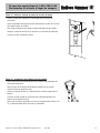
Step 12 – Connect Gas Line to Cylinder
The pressure regulator and hose assembly supplied with the appliance
must be used and replacements must be those specified by the
manufacturer.
• Slide full Propane Cylinder onto Heater Base.
• Attach Gas Line to Cylinder by turning black plastic knob clockwise over
Cylinder valve until tight.
Note: Be careful not to kink flexible hose of Gas Line.
• Secure cylinder in place by attaching loose end of Cylinder Restraint
Chain to hole in right leg.
Step 13 – Check for Leaks
• Make 2-3 oz. of leak check solution by mixing one part liquid
dishwashing soap and three parts water.
• Turn cylinder valve ON.
• Check Gas Line / Control Valve for leaks:
• Spoon several drops of solution onto Gas Line and Control Valve
connection.
• Inspect the solution at the connection to look for bubbles.
• If NO bubbles appear, then the connection is secure.
• If bubbles appear, there is a leak -
• Turn Cylinder valve OFF.
• Loosen screw on Clip.
• Release Gas Line fitting from control valve and re-attach making sure
connection is secure (see Step 9).
• Retighten Clip.
• If you continue to see bubbles after several attempts, contact
1-800-762-1142 for assistance.
Check Gas Line / Cylinder valve for leaks:
• Turn cylinder valve ON.
• Spoon several drops of solution onto Gas Line and Cylinder valve
connection.
• Inspect the solution at the connection to look for bubbles.
• If NO bubbles appear, then the connection is secure.
• If bubbles appear, there is a leak:
• Turn Cylinder valve OFF.
• Release Gas Line fitting from Cylinder valve and re-attach making sure
connection is secure (see Step 12).
• If you continue to see bubbles after several attempts, contact
1-800-762-1142 for assistance.
• Turn Cylinder Valve OFF.

Contact 1-800-762-1142 for assistance.
Do not return to place of purchase.
®
Owner’s manual: model 235000 outdoor patio heater 6/11/04
11
Contact 1-800-762-1142 for assistance.
Do not return to place of purchase.
®
Owner’s manual: model 235000 outdoor patio heater 6/11/04
12
Step 14 – Replace Engine Access Panel
Slide Igniter wire onto Igniter post.
Slide tab at top of Access Panel into slot in Emitter bottom.
Rotate Panel down until holes line up at bottom.
Secure Access Panel in place with thumbscrew.
Replace Control Knob.
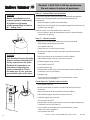
Step 15 – Install Igniter Battery
Remove battery cover cap by turning cap counterclockwise.
Install (1) AA battery. Negative end of battery goes in first.
Replace battery cover cap by turning cap clockwise.
Note: Once you have successfully completed assembly steps 1-14 you
are ready to begin operating your heater.

Contact 1-800-762-1142 for assistance.
Do not return to place of purchase.
®
Owner’s manual: model 235000 outdoor patio heater 6/11/04
13
Contact 1-800-762-1142 for assistance.
Do not return to place of purchase.
®
Owner’s manual: model 235000 outdoor patio heater 6/11/04
14
Operation
Caution: Do NOT attempt to operate heater until you have read and
understand all precautions in section 1 “Safety First.”
Before Turning Gas Supply ON
• Your heater was designed and approved for OUTDOOR USE ONLY.
DO NOT use it inside a building, garage, or any other enclosed area.
• Make sure surrounding areas are free of combustible materials,
gasoline, and other flammable vapors or liquids.
• Ensure that there is no obstruction to air ventilation.
• Be sure all gas connections are tight and there are no leaks.
• Be sure the access panel is clear of debris.
• Be sure any component removed during assembly or servicing is
replaced and fastened prior to starting.
Before Lighting
• Heater should be thoroughly inspected before each use, and by a
qualified service person at least annually.
• If relighting a hot heater, always wait at least 5 minutes.
• Inspect the hose assembly for evidence of excessive abrasion, cuts,
or wear. Suspected areas should be leak tested. If the hose leaks, it
must be replaced prior to operation. Only use the replacement hose
assembly specified by manufacturer.
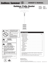
Lighting
Note: This heater is equipped with a Pilot Light that allows for safer
startups and shutdowns. Pilot must be lit before Main Burner can be
started.
• Turn Cylinder Valve OFF.
• Push Control Knob IN and turn to OFF.
• Wait 5 minutes for any gas to clear.
• Turn Cylinder Valve ON.
• Open Viewing Hole by sliding cover to either side.
• Push Control Knob IN and rotate to Pilot position.
• Note - For initial start or after any cylinder change, hold Control Knob
IN for 2 minutes to purge air from gas lines before proceeding.
• Push Igniter button once. Pilot Light flame will appear and be visible
through Viewing Hole.
• Release Control Knob after 30 seconds. Pilot Light will remain lit.
If not, return to step 1.
• Turn Control Knob to ON. Main Burner will light immediately. Flame is
visible through Viewing Hole. If not, return to step 1.
WARNING
FOR YOUR SAFETY
• Do NOT attempt to operate
heater until you have
read and understand all
precautions in Section 1
“Safety First.” Failure to
do so can result in serious
personal injury, death, or
property damage.
• If at any time you are unable
to light burner and smell
gas, wait 5 minutes to allow
gas to dissipate before
attempting to light heater.
• Do NOT touch emitter or
dome or move heater for at
least 45 minutes after use.
OFF
OFF
LOW
LOW
Pilot
Pilot
(Push in)
HIGH
HIGH
Pilot
Pilot
(Push in)
HIGH
HIGH
LOW
LOW
OFF
OFF
View Hole

Contact 1-800-762-1142 for assistance.
Do not return to place of purchase.
®
Owner’s manual: model 235000 outdoor patio heater 6/11/04
13
Contact 1-800-762-1142 for assistance.
Do not return to place of purchase.
®
Owner’s manual: model 235000 outdoor patio heater 6/11/04
14
WARNING
FOR YOUR SAFETY
Be careful when attempting
to manually ignite this heater.
Holding in the control know for
more than 10 seconds before
igniting the gas will cause a
ball of ame upon ignition.
• If for some reason your ignitor fails to deliver a spark, your heater can
be started by inserting a lit match through the pilot view hole while
pushing the control knob in while in the PILOT position.
If you experience any ignition problem consult “Troubleshooting” on
page 16.
Caution: Avoid inhaling fumes emitted from the heater’s first use.
Smoke and odor from the burning of oils used in manufacturing will
appear. Both smoke and odor will dissipate after approximately 30
minutes. The heater should NOT produce thick black smoke.
Note: The burner may be noisy when initially turned on. To eliminate
excessive noise from the burner, turn the Control Knob to the Pilot
position. Then, turn the knob to the level of heat desired.
When heater is ON:
Emitter screen will become bright red due to intense heat. The color is
more visible at night.
Burner will display tongues of blue and yellow flame. These flames
should not be yellow or produce thick black smoke, indicating an
obstruction of airflow through the burners. The flame should be blue
with straight yellow tops.
If excessive yellow flame is detected, turn off heater and consult
“Troubleshooting” on page 16.
Re-lighting
Note: For your safety, Control Knob cannot be turned OFF without first
depressing Control Knob in PILOT position and then rotating it to OFF.
Turn Control Knob to OFF.
Wait at least 5 minutes, to let gas dissipate, before attempting to relight
Pilot.
Repeat the “Lighting” steps on prior page.
Shut Down
Turn Control Knob clockwise to Pilot. (Normally, burner will make a slight
popping sound when extinguished.) Burner will extinguish but Pilot will
remain ON.
To extinguish Pilot, depress Control Knob and continue to turn it
clockwise to OFF.
Turn Cylinder Valve clockwise to OFF and disconnect Regulator when
heater is not in use.
Note: After use, some discoloration of the emitter screen is normal.
WARNING
FOR YOUR SAFETY
Heater will be hot after use.
Handle with extreme care.

Contact 1-800-762-1142 for assistance.
Do not return to place of purchase.
®
Owner’s manual: model 235000 outdoor patio heater 6/11/04
15
Contact 1-800-762-1142 for assistance.
Do not return to place of purchase.
®
Owner’s manual: model 235000 outdoor patio heater 6/11/04
16
Operation Checklist
For a safe and pleasurable heating experience, perform this check before
each use.
Before Operating
q I am familiar with entire owner’s manual and understand all precautions
noted in “Safety First”.
q All components are properly assembled, intact and operable.
q No alterations have been made.
q All gas connections are secure and do not leak.
q Wind velocity is below 10 mph.
q Outdoor temperature is greater than 40 degrees F.
q Heater is outdoors (outside any enclosure).
q There is adequate fresh air ventilation.
q Heater is away from gasoline or other flammable liquids or vapors.
q Heater is away from windows, air intake openings, sprinklers and other
water sources.
q Heater is at least 36” clearance (top) and 24” clearance (side)
combustible materials.
q Heater is on a hard and level surface.
q There are no signs of spider or insect nests.
q All burner passages are clear.
q All air circulation passages are clear.
q Children, pets, clothing, flammable materials and items that can be
damaged from radiant heat are away from the heater.
q Children and adults in the area have been alerted to the high
temperature hazards: especially burns and clothing fires.
q Children and adults in the area have been warned not to touch heater
near engine during operation and until unit has cooled.
After Operation
q Gas control is in OFF position.
q Gas tank valve is OFF
q Disconnect Gas line.
q Heater is upright in a secure location.

Contact 1-800-762-1142 for assistance.
Do not return to place of purchase.
®
Owner’s manual: model 235000 outdoor patio heater 6/11/04
15
Contact 1-800-762-1142 for assistance.
Do not return to place of purchase.
®
Owner’s manual: model 235000 outdoor patio heater 6/11/04
16
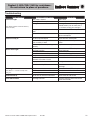
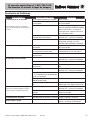
Troubleshooting
If the problem is: And this condition exists: Then do this
Pilot won’t light
Note: Heater operates at reduced efficiency
below 40ºF (5ºC).
Tank valve is closed
Blockage in orifice or pilot tube
Air in gas line
Low gas pressure with tank valve fully
open
Igniter fails
Open valve
Clean or replace orifice or pilot tube
Open gas line and bleed it (pressing
control knob in) for not more than 1
- 2 minutes or until you smell gas
Turn tank valve OFF and replace tank
Use match to light pilot; obtain new
igniter and replace
Pilot won’t stay lit
Dirt built up around pilot
Connection between gas valve and
pilot assembly is loose
Thermocouple is not operating
correctly
Clean dirt from around pilot
Tighten connection and perform leak
check
Replace thermocouple
Burner won’t light
Gas pressure is low
Blockage in orifice
Control knob is not in ON position
Turn tank valve OFF and replace tank
Clear blockage
Turn control knob to ON
Burner flame is low
Gas pressure is low
Outdoor temperature is less than 40ºF
and tank is less than 1/4 full
Supply hose is bent or kinked
Control knob fully ON
Turn tank valve OFF and replace tan
Use a full tank
Straighten hose
Check burner and orifices for
blockage
Emitter glows uneven
Note: Bottom 1” of emitter normally does
NOT glow.
Gas pressure is low
Base is not on a level surface
Heater is level
Turn tank valvue OFF and replace tank
Place heater on a level surface
Clean burner
Carbon build-up
Dirt or film on reflector and emitter Clean reflector and emitter
Thick black smoke
Blockage in burner Remove blockage and clean burner
inside and outside

Contact 1-800-762-1142 for assistance.
Do not return to place of purchase.
®
Owner’s manual: model 235000 outdoor patio heater 6/11/04
17
Contact 1-800-762-1142 for assistance.
Do not return to place of purchase.
®
Owner’s manual: model 235000 outdoor patio heater 6/11/04
18
Maintenance
To enjoy years of outstanding performance from your heater, make sure
you perform the following maintenance activities on a regular basis:
Keep exterior surfaces clean.
Use warm soapy water for cleaning. Never use flammable or corrosive
cleaning agents.
While cleaning your unit, be sure to keep the area around the burner
and pilot assembly dry at all times. Do not submerge the control valve
assembly. If the gas control is submerged in water, do NOT use it. It
must be replaced.
Air flow must be unobstructed. Keep controls, burner, and circulating air
passageways clean. Signs of possible blockage include:
Gas odor with extreme yellow tipping of flame.
Heater does NOT reach the desired temperature.
Heater glow is excessively uneven.
Heater makes popping noises.
Spiders and insects can nest in burner or orifices. This dangerous
condition can damage heater and render it unsafe for use. Clean burner
holes by using a heavy-duty pipe cleaner. Compressed air may help
clear away smaller particles.
Carbon deposits may create a fire hazard. Clean dome and emitter with
warm soapy water if any carbon deposits develop.
Note: In a salt-air environment (such as near an ocean), corrosion occurs
more quickly than normal. Frequently check for corroded areas and repair
them promptly.
WARNING
FOR YOUR SAFETY
• Do NOT touch or move
heater for at least 45 minutes
after use.
• Dome is hot to the touch.
• Allow dome to cool before
touching.
TIP:
Use high-quality automobile wax to help maintain the appearance of
your heater. Apply to exterior surfaces from the pole down. Do not
apply to emitter screen or domes.

Contact 1-800-762-1142 for assistance.
Do not return to place of purchase.
®
Owner’s manual: model 235000 outdoor patio heater 6/11/04
17
Contact 1-800-762-1142 for assistance.
Do not return to place of purchase.
®
Owner’s manual: model 235000 outdoor patio heater 6/11/04
18
Storage
Between uses:
Turn Control Knob OFF.
Disconnect LP source.
Store heater upright in an area sheltered from direct contact with
inclement weather (such as rain, sleet, hail, snow, dust and debris).
If desired, cover heater to protect exterior surfaces and to help prevent
build up in air passages.
Note: Wait until heater is cool before covering.
During periods of extended inactivity or when transporting:
Turn Control Knob OFF.
Disconnect LP source and move to a secure, well-ventilated location
outdoors.
Store heater upright in an area sheltered from direct contact with
inclement weather (such as rain, sleet, hail, snow, dust and debris).
If desired, cover heater to protect exterior surfaces and to help prevent
build up in air passages.
Never leave LP cannister exposed to direct sunlight or excessive heat.
Note: Wait until heater is cool before covering.
Service
To learn how to service and procure parts for worn out, defective or
damaged components contact 1-800-762-1142 for assistance or e-mail
[email protected]. Please supply model number and
serial ID number for best service support. These numbers can be found on
a label on the rear of the Valve Housing.
Caution: Use only original equipment replacement parts. Use of
unauthorized parts or modification of parts will void warranty and
create an unsafe condition.
Caution: Always allow heater to cool before attempting service.

Contact 1-800-762-1142 for assistance.
Do not return to place of purchase.
®
Owner’s manual: model 235000 outdoor patio heater 6/11/04
19
Contact 1-800-762-1142 for assistance.
Do not return to place of purchase.
®
Owner’s manual: model 235000 outdoor patio heater 6/11/04
20
Limited Warranty
Blue Rhino Global Sourcing, LLC (“Vendor”) warrants to the original retail purchaser of this heater,
and to no other person, that if this heater is assembled and operated in accordance with the
printed instructions accompanying it, then for a period of one (1) year from the date of purchase,
all parts in such heater shall be free from defects in material and workmanship. Vendor may require
reasonable proof of your date of purchase from an authorized retailer or distributor. Therefore,
you should retain your sales slip or invoice. This Limited Warranty shall be limited to the repair
or replacement of parts, which prove defective under normal use and service and which Vendor
shall determine in its reasonable discretion upon examination to be defective. Before returning any
parts, you should contact Vendor’s Customer Service Department using the contact information
listed below. If Vendor confirms, after examination, a defect covered by this Limited Warranty
in any returned part, and if Vendor approves the claim, Vendor will replace such defective part
without charge. If you return defective parts, transportation charges must be prepaid by you.
Vendor will return replacement parts to the original retail purchaser, freight or postage prepaid.
This Limited Warranty does not cover any failures or operating difficulties due to accident, abuse,
misuse, alteration, misapplication, improper installation or improper maintenance or service by
you or any third party, failure to perform normal and routine maintenance on the heater, shipping
damage, normal adjustment to burner, damage or repairs related to insects, birds, or animals of
any kind, and damage due to weather conditions as set out in this owner’s manual. In addition,
the Limited Warranty does not cover damage to the finish, such as scratches, dents, discoloration,
rust or other weather damage, after purchase.
This Limited Warranty is in lieu of all other express warranties. Vendor disclaims all warranties for
products that are purchased from sellers other than authorized retailers or distributors. AFTER
THE PERIOD OF THE ONE (1)-YEAR EXPRESS WARRANTY, VENDOR DISCLAIMS ANY AND
ALL IMPLIED WARRANTIES, INCLUDING WITHOUT LIMITATION THE IMPLIED WARRANTIES
OF MERCHANTABILITY AND FITNESS FOR A PARTICULAR PURPOSE. FURTHER, VENDOR
SHALL HAVE NO LIABILITY WHATSOEVER TO PURCHASER OR ANY THIRD PARTY FOR ANY
SPECIAL, INDIRECT, PUNITIVE, INCIDENTAL, OR CONSEQUENTIAL DAMAGES. Vendor assumes
no responsibility for any defects caused by third parties. This Limited Warranty gives the purchaser
specific legal rights; a purchaser may have other rights depending upon where he or she lives.
Some jurisdictions do not allow the exclusion or limitation of special, incidental or consequential
damages, or limitations on how long a warranty lasts, so the above exclusion and limitations may
not apply to you.
Vendor does not authorize any person or company to assume for it any other obligation or liability
in connection with the sale, installation, use, removal, return, or replacement of its equipment, and
no such representations are binding on Vendor.
Blue Rhino Global Sourcing, LLC
104 Cambridge Plaza Drive
Winston-Salem, North Carolina 27104 USA
(800) 762-1142
24 Hour Fax: (336) 659-6743
Page is loading ...
Page is loading ...
Page is loading ...
Page is loading ...
Page is loading ...
Page is loading ...
Page is loading ...
Page is loading ...
Page is loading ...
Page is loading ...
Page is loading ...
Page is loading ...
Page is loading ...
Page is loading ...
Page is loading ...
Page is loading ...
Page is loading ...
Page is loading ...
Page is loading ...
Page is loading ...
Page is loading ...
Page is loading ...
-
 1
1
-
 2
2
-
 3
3
-
 4
4
-
 5
5
-
 6
6
-
 7
7
-
 8
8
-
 9
9
-
 10
10
-
 11
11
-
 12
12
-
 13
13
-
 14
14
-
 15
15
-
 16
16
-
 17
17
-
 18
18
-
 19
19
-
 20
20
-
 21
21
-
 22
22
-
 23
23
-
 24
24
-
 25
25
-
 26
26
-
 27
27
-
 28
28
-
 29
29
-
 30
30
-
 31
31
-
 32
32
-
 33
33
-
 34
34
-
 35
35
-
 36
36
-
 37
37
-
 38
38
-
 39
39
-
 40
40
-
 41
41
-
 42
42


Blue Rhino 235000 User manual
- Category
- Barbecues & grills
- Type
- User manual
- This manual is also suitable for
Ask a question and I''ll find the answer in the document
Finding information in a document is now easier with AI
in other languages
- español: Blue Rhino 235000 Manual de usuario
Related papers
-
 Blue Rhino 163010 User manual
-
 Blue Rhino 235020 User manual
-
 Blue Rhino 223600 User manual
-
Uniflame 235000 Owner's manual
-
Endless Summer Endless Summer 235000 Owner's manual
-
-
-
 Blue Rhino Charmglow GWU9300H User manual
-
 Blue Rhino GWU512B User manual
-


Other documents
-
Everbilt DPJC125 User manual
-
-
NewAir APH-4000PV User manual
-
Goldair GGOH200 Operating Instructions Manual
-
USSC HCPHPRM User manual
-
-
-
-
-