Page is loading ...
(91.4 cm)
(7&2 cm) et 36' (91,
Table of Contents/Tabb des matieres ............................................................................. 2
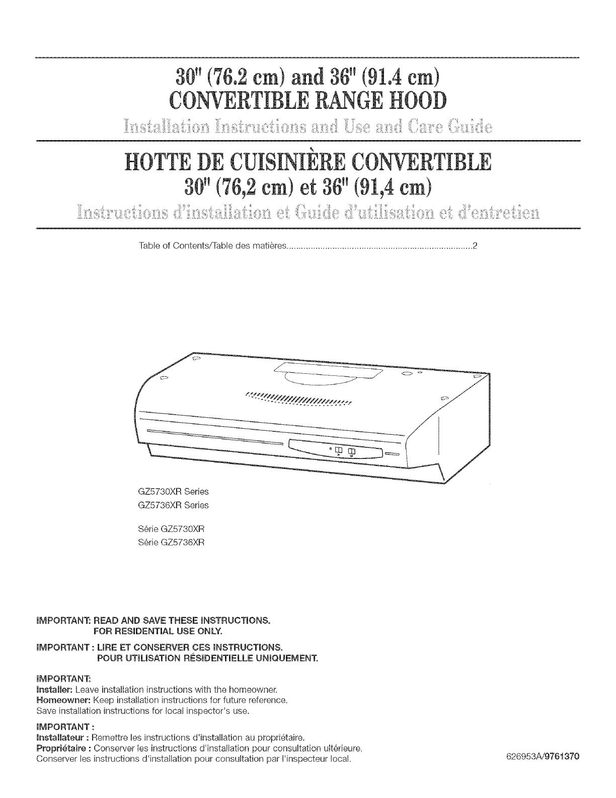
GZ5730XR Series
GZ5736XR Series
S&rie GZ5730XR
S6rie GZ5736XR
iMPORTANT: READ AND SAVE THESE iNSTRUCTiONS,
FOR RESiDENTiAL USE ONLY.
iMPORTANT : LIRE ET CONSERVER CES iNSTRUCTiONS,
POUR UTIUSATION RESIDENTIELLE UNIQUEMENT.
iMPORTANT:
installer: Leave installation instructions with the homeowner,
Homeowner: Keep installation instructions for future reference.
Save installation instructions for Iocat inspector's use.
iMPORTANT :
lnstallateur : Remettre les instructions d'instailation au propri6taire.
Propri_taire : Conserver Ies instructions d'instailation pour consultation uIterieure.
Conserver les instructions d'installation pour consultation par Hnspecteur local.
626953A/9761370
TABLEOF CONTENTS
RANGE HOOD SAFETY ............................... 2
iNSTALLATiON REQUIREMENTS ....................... 4
Tools and Parts ..................................... 4
LocationRequirements ............................ 4
EJectdcaIRequirements ............................ 4
Venting Requirements ............................. 5
INSTALLATION INSTRUCTIONS ........................6
Prepare Location ................................. 6
Prepare the Hood ................................. 6
Make EIectdca[Connection ......................... 8
Instal[Range Hood ................................ 9
Complete Installation .............................. 9
RANGE HOOD USE .................................. 10
Operation ...................................... 10
RANGE HOOD CARE ................................ 10
CHeaning and Maintenance ........................ 10
REQUESTING ASSISTANCE OR SERVICE .............. 1t
RANGE HOOD WARRANTY ........................... 12
%
TABLEDESMATIERES
S_:CURITE DE LA HOTTE DE CUISINI_:RE .............. 13
EXIGENCES D'INSTALLATION ........................ 15
Outillage et pi6ces ..................................15
Exigences d'emphcement ......................... 15
Specificationselectriques......................... 16
Exigences concernant Uevacuation ................. 16
INSTRUCTIONS D"INSTALLATION ..................... 18
Preparation de Vemplacement ..................... 18
Preparation de la hotte ........................... 18
Raccordement eIectrique.......................... 20
Installationde [ahottede cuisiniere................21
Achever ['installation............................. 21
UTILISATION DE LA HOTTE DE CUISINI_:RE ............ 22
Fonctionnement ................................. 22
ENTRETIEN DE LA HOTTE DE OUISINI_:RE ............. 22
Nettoyage et entretien ............................ 22
DEMANDE D"ASSlSTANCE OU DE SERVICE ............ 23
GARANTIE DE LA HOTTE DE CUISINI_:RE .............. 24
RANGEHOODSAFETY
Your safety and the safety of others are very important.
We have provided many important safety messages in this manuaI and on your appliance. AIways read and obey aII safety
messages.
This is the safety alert symbol.
This symbol alerts you to potentiaI hazards that can kiII or hurt you and others.
All safety messages will follow the safety alert symbol and either the word "DANGER" or "WARNING."
These words mean:
You can be killed or seriousJy injured if you don't immediately
foJlow instructions.
You can be kilJed or seriousJy injured if you don't foJJow
instructions.
AII safety messages wiII tell you what the potentiaI hazard is, tell you how to reduce the chance of injury, and tell you what can
happen if the instructions are not followed.
IMPORTANT SAFETY INSTRUCTIONS
WARNmNG: TO REDUCE THE RISK OF FIRE, ELECTRIC
SHOCK, OR INJURY TO PERSONS, OBSERVE THE
FOLLOWING:
Use this unit only in the manner intended by the
manufacturer. If you have questions, contact the
manufacturer.
Before servicing or cleaning the unit, switch the power off at
the service panel disconnecting means to prevent power
from being switched on accidentally. When the service
disconnecting means cannot be locked, securely fasten a
prominent warning device, such as a tag, to the service
panel.
Installation work and electrical wiring must be done by
qualified person(s) in accordance with all applicable codes
& standards, including fire-rated construction.
Sufficient air is needed for proper combustion and
exhausting of gases through the flue (chimney) of fuel
burning equipment to prevent backdrafting. Follow the
heating equipment manufacturer's guideline and safety
standards such as those published by the National Fire
Protection Association (NFPA), the American Society for
Heating, Refrigeration and Air Conditioning Engineers
(ASHRAE), and the local code authorities.
When cutting or drilling into wall or ceiling; do not damage
electrical wiring and other utilities.
Ducted systems must always be vented outdoors.
CAUTION: For general ventilating use only. Do not use
to exhaust hazardous or explosive materials and vapors.
CAVTION: To reduce risk of fire and to properly exhaust
air, be sure to duct air outside - do not vent exhaust air into
spaces within walls ceilings, attics, crawl spaces, or
garages.
WARNING: TO REDUCE THE RISK OF FIRE, USE ONLY
METAL DUCTWORK.
WARNING: TO REDUCE THE RISK OF A RANGE TOP
GREASE FIRE:
Never leave the surface units unattended at high settings.
Boilovers cause smoking and greasy spillovers that may
ignite. Heat oils slowly on low or medium settings.
Always turn hood ON when cooking at high heat or when
flameing food (i.e. Crepes Suzette, Cherries Jubilee,
Peppercorn Beef Flambe).
Clean ventilating fans frequently. Grease should not be
allowed to accumulate on fan or filter.
Use proper pan size. Always use cookware appropriate for
the size of the surface element.
WARNING: TO REDUCE THE RISK OF INJURY TO
PERSONS IN THE EVENT OF A RANGE TOP GREASE
FIRE, OBSERVE THE FOLLOWING: _
SMOTHER FLAMES with a close fitting lid, cookie sheet, or
other metal tray, then turn off the gas burner or electric
element BE CAREFUL TO PREVENT BURNS. If the
flames do not go out immediately, EVACUATE AND CALL
THE FIRE DEPARTMENT.
NEVER PICK UP A FLAMING PAN = you may be burned.
DO NOT USE WATER, including wet dishcloths or towels :
a violent steam explosion will result.
Use an extinguisher ONLY if:
= You know you have a class ABC extinguisher, and you
already know how to operate it.
= The fire is small and contained in the area where it
started.
= The fire department is being called.
= You can fight the fire with your back to an exit
aBased on "Kitchen Fire Safety Tips" published by NFPA.
WAR NmNG: To reduce the risk of fire or electrical shock,
do not use this fan with any solid:state speed control
device.
SAVE THESE INSTRUCTIONS

iNSTALLATiONREQUIREMENTS
Product Dimensions
Gather the required tools and parts before starting installation.
Read and follow the safety instructions provided with any tools
listed here.
Tools needed:
[] levet
[] compass or 8" (20.3 cm) circle template
[] flat blade screwdriver
[] Phillips screwdriver
[] pliers
[] metal snips
[] drill
[] 1 ¼" and 1A"driII bits
[] pencil
[] ruler
[] keyhole saw
[] saber saw
29-7/8" (75,9 cm) model: GZ5730 Series
35-7/8" (91,1 cm) model: GZ5736 Series _
__:_<_di<<<<////////"'_""" 7-1/4"
.............. (18,4 cm)
_A
[] duct tape
Parts needed:
[] UL- or CSA-Iisted, 1/,. (12.5 mm) strain relief
(used with direct wiring only)
[] power supply cable
[] 7" (17.8 cm) round damper if using
7" (17.8 cm) round vent system
[] 2 twist-on electrical wire connectors
IMPORTANT: Observe all governing codes and ordinances.
Hood location should be away from strong draft areas, such as
windows, doors and strong heating vents.
Grounded electrical outlet is required. See "Electrical
Requirements" section.
it is recommended that the hood be fastened into solid wood. if
fastening into drywall or other material, wall anchors or screws
with toggle nuts (purchased separately) must be used.
This hood is factory set for non-venting (recirculating)
installations. For vented installations see "installation instructions"
section.
if this hood will be used as a non-vented installation you will also
need to purchase a 30" (76.2 cm) Filter Kit, No. 4396291 or
36" (91.4 cm) Filter Kit, No. 4396292 from your dealer.
All openings in ceiling and wall where the hood will be installed
must be sealed.
in U.S. only: For power cord connected installations, a UL-listed
range hood cord-connection kit (part no. 99524057) must be
used. Cord kit has not been evaluated for use in Canada.
IMPORTANT: The hood must be electrically grounded in
accordance with local codes and ordinances, or in the absence of
local codes, with the National Electrical Code, ANSI/NFPA 70,
latest edition, or Canadian Electrical Code, CSA C22.1.
if codes permit and a separate ground wire is used, it is
recommended that a qualified electrical installer determine that
the ground path is adequate.
A copy of the above code standards can be obtained from:
National Fire Protection Association
One Batterymarch Park, Quincy, MA 02269
CSA Internationa!
8501 East Pleasant Valley Road
Cleveland, Ohio 44131-5575
[] A 120-volt, 60-Hz, AC-only, 15-amp, fused electrical circuit is
required. A time-delay fuse or circuit breaker is also
recommended, it is recommended that a separate circuit
serving only this hood be provided.
[] Do not ground to a gas pipe.
[] Check with a qualified electrician if you are not sure range
hood is properly grounded.
[] Do not have a fuse in the neutral or ground circuit.
[] The range hood must be connected with copper wire only.
[] The range hood should be connected directly to the fused
disconnect (or circuit breaker) box through flexible armored or
nonmetallic sheathed copper cable.
[] A UL- or CSA-listed strain relid must be provided at each end
of the power supply cable. Wire sizes (copper wire only) and
connections must conform with the rating of the appliance as
specified on the model/serial rating plate.
[] Wire sizes must conform to the requirements of the National
Electrical Code, ANSI/NFPA 70, latest edition, or CSA
Standards C22.1-94, Canadian Electrical Code, Part 1 and
C22.2 No. 0-M91, latest edition, and all local codes and
ordinances.

[] Ventsystem(ifneeded)forinstallationisnotincluded.
[] Ventsystemmustterminatetotheoutside.
[] Donotterminatetheventsysteminanatticorother
enclosedarea.
[] Donotuse4"(10.2cm)laundry-typewallcaps.
[] Usemetalventonly.Rigidmetalventisrecommended.Do
notuseplasticormetalfoilvent.
Forthemostefficientandquietoperation:
[] Thelengthoftheventsystemandnumberofelbowsshould
bekepttoaminimumtoprovideefficientperformance.The
sizeoftheventsystemshouldbeuniform.
[] Donotinstalltwoelbowstogether.
[] Ventsystemcanterminateeitherthroughtherooforwail.
[] Forthemostefficientandquietoperation,itisrecommended
thattherangebeventedverticallythroughtheroofthrough
7"(17.8cm)roundventsystem.
[] Useducttapetosea!alljointsintheventsystem.
[] Usecaulkingtosealexteriorwallorroofopeningaround
thecap.
VentingMethods
Determinewhichoutsideventingmethodneedstobeused.Itis
recommendedthattheventsystembeinstalledbeforeinstalling
thehood.
NOTE:Ifanon-vented(recirculating)installationisdesired,follow
instructionsinthe"MakeElectricalConnection"section.
7" (17.8 cm) round
or 3-1/4" x 10" , roof cap 7" (17,8 cm)
(8,3 x 25,4 cm) ....... round
round damper
(purchased
separately)
i I
24"(61cm) to _
30"(782 cm)
!
abovecooking
surface
Roof venting Wall venting
Calculating Vent System Length
To calculate the length of the system you need, add the
equivalent feet (meters) for each vent piece used in the system.
Use 31/4'' x 10" (8.3 x 25.4 cm) or 7" (17.8 cm) round vent with a
maximum length of 65 feet (19.8 m) for vent system. For best
performance, use no more than three 90° elbows. To calculate the
length of system you need, add the equivalent feet for each vent
piece used in the system. See the examples below.
3-1/4" x 10" (8.3 x 25.4 cm) vent system
Recommended standard fittings
Vent piece 31//' x 10" (8.3 x 25.4 cm)
31/4"x 10" 5 feet
(8.3 x 25.4 cm) (1.5 m)
900elbow
31/4'' x 10" 12 feet
(8.3 x 25.4 cm) (3.7 m)
flat elbow
31/4'' x 10" 0 feet
(8.3 x 25.4 cm) (0 m)
wall cap
3-1/4" x 10"
(8_3x 25_4 cm) _6 ft. 1.8 m _ wall cap
e,bow _ ____ Examp,e vent
I _J system
2ft. 1 -- 90 elbow = 5 ft. (1.5 m)
(u_lm_l I_ ' 8 ft. (2.4 m) straight = 8 ft. (2.4 m)
Jh' '
_-_ 1 -- wall cap = 0 ft. (0 m)
h_J system length = 13 ft. (3.9 m)
7" (17.8 cm} vent system
Recommended standard fittings
Vent piece
450elbow
900 elbow
7" (17.8 cm)
wall cap
7" (!7.8 cm) round
2.5 feet
(0.8m)
5.0 feet
(1.5 m)
0 feet
(0m)
Vent piece
31/4,,x 10,,
(8.3 x 25.4 cm
to 7" (17.8 cm)
31/4,,x 10,,
(8.3 x 25.4 cm
to 7" (17.8 cm)
90° elbow
F" (!7.8 cm) round
4.5 feet
/14©.....
90° elbow _6 ft. (1.8 m)------X_l wall cap
_.q -----._--_ Example vent
( I
ft.
system length = 13 ft. (3.9 m)
iNSTALLATiONiNSTRUCTiONS
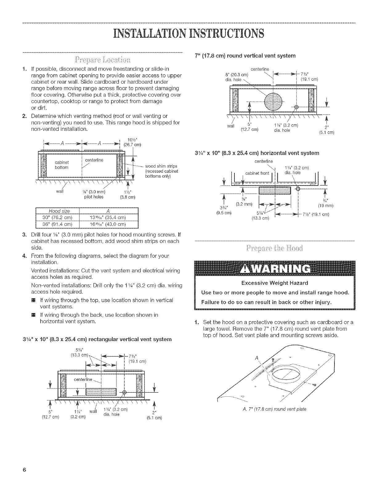
1. If possible, disconnect and move freestanding or slide-in
range from cabinet opening to provide easier access to upper
cabinet or rear wall. Slide cardboard or hardboard under
range before moving range across floor to prevent damaging
floor covering. Otherwise put a thick, protective covering over
countertop, cooktop or range to protect from damage
or dirt.
2. Determine which venting method (roof or wall venting or
non-venting) you need to use. This range hood is shipped for
non-vented installation.
7" {17,8 cm) round vertica_ vent system
centerline
I I ,,
8" (20.3 ore) "_. _ 7 F*
dia. hole.\ i" i (19_1 cm)
! i ,
wall 5" 1W' (3,2cm) 2"
(122 cm) dis, hole (5_1cm)
3,
4,
wood shim strips
(recessedcabinet
bottoms only)
wall W' (3.0 ram) 1F,"
pilot holes (3.8 cm)
Hood size A
30" (76.2 cm) 13_%'' (35.4 cm)
36" (91.4 cm) 16_5A6'' (43.0 cm)
Drill four 1/_,,(3.0 mm) pilot holes for hood mounting screws. If
cabinet has recessed bottom, add wood shim strips on each
side.
From the following diagrams, select the diagram for your
installation.
Vented installations: Cut the vent system and electrical wiring
access holes as required.
Non-vented installations: Drill only the 11/4"(3.2 cm) dis. wiring
access hole required.
[] If wiring through the top, use location shown in vertical
vent systems.
[] If wiring through the back, use location shown in
horizontal vent system.
31/4" x 10" {8,3 x 25,4 cm) rectangular vertica_ vent system
5w'
31/4"x 10" (8,3 x 25,4 cm) horizonta_ vent system
centerline
""..q 1¼" (3.2 cm)
/_ . ! i
(9_5cm) 15;_;_ i_-----_@ 7,/,,, (19.1 cm)
( . )
1. Set the hood on a protective covering such as cardboard or a
large towe!. Remove the 7" (17.8 cm) round vent plate from
top of hood. Set vent plate and mounting screws aside.
2"
(12.7 cm) (3.2 cm) dis. hole (5.1 cm)
A. 7" (17,8 cm) round vent plate
2,
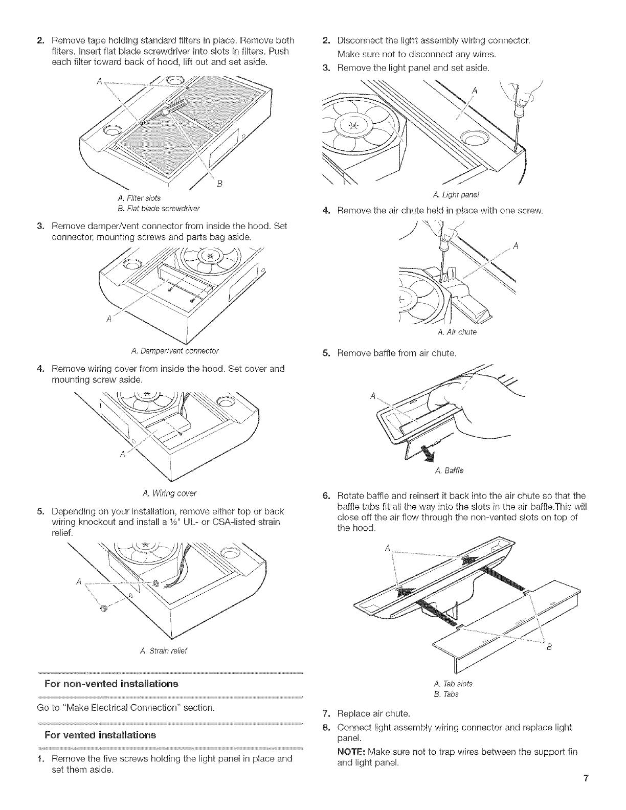
Remove tape holding standard filters in place. Remove both
fiiters, insert flat blade screwdriver into slots in filters. Push
each filter toward back of hood, lift out and set aside.
A
3,
, B
A. Filterslots
B,Flatbladescrewdriver
Remove damper/vent connector from inside the hood. Set
connector, mounting screws and parts bag aside.
A,Damper/ventconnector
4, Remove wiring cover from inside the hood. Set cover and
mounting screw aside.
5,
A, Wiring cover
Depending on your installation, remove either top or back
wiring knockout and install a 1/,,,UL- or CSA-listed strain
relief.
A. Strain relief
For r_or_-vented installations
Go to "Make EbctricaI Connection" section.
For vented installations
1, Remove the five screws holding the light panel in place and
set them aside.
2, Disconnect the light assembly wiring connector.
Make sure not to disconnect any wires.
3, Remove the light panel and set aside.
\
A \
5,
6,
7,
8,
A. Light panel
Remove the air chute hetd in place with one screw.
J
A,Airchute
Remove baffle from air chute.
A
A, Baffle
Rotate baffle and reinsert it back into the air chute so that the
baffle tabs fit all the way into the slots in the air baffle.This will
close off the air flow through the non-vented slots on top of
the hood.
B
A. Tabslots
B. Tabs
Replace air chute.
Connect light assembly wiring connector and replace light
panel.
NOTE: Make sure not to trap wires between the support fin
and light panel.
g,
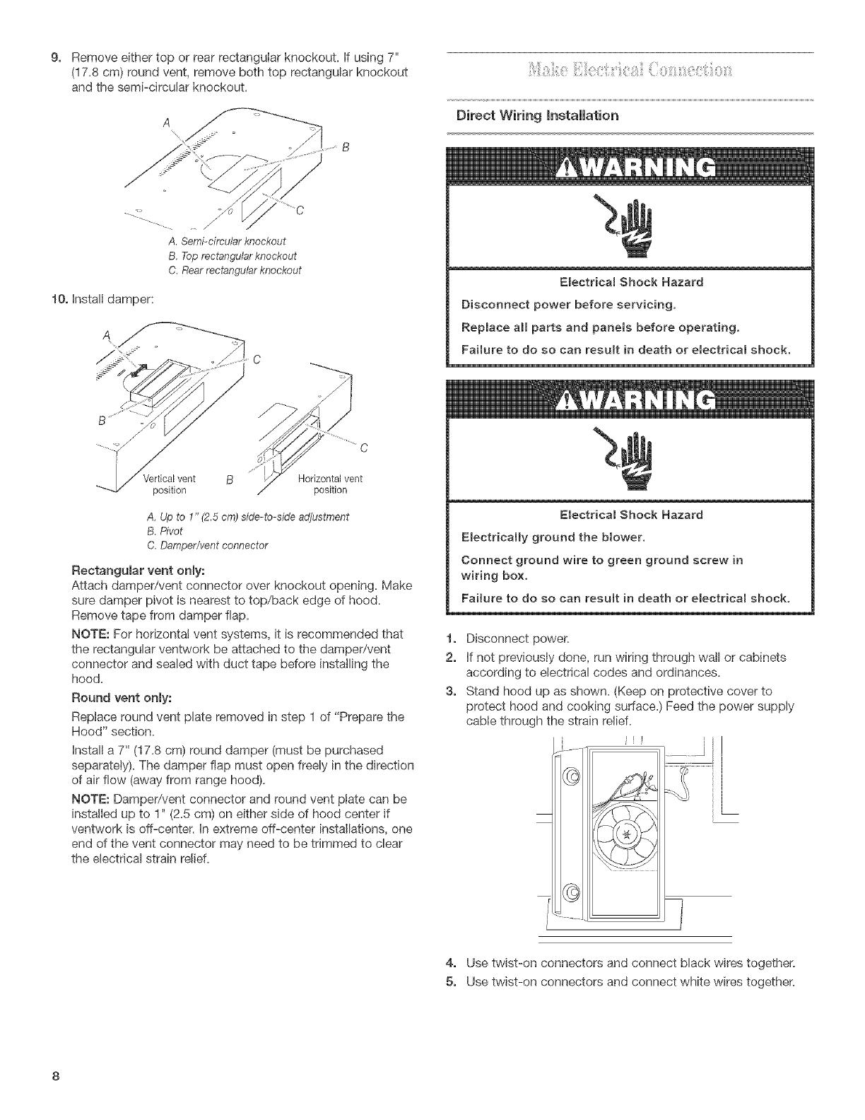
Remove either top or rear rectangular knockout, if using 7"
(17.8 cm) round vent, remove both top rectangular knockout
and the semi-circular knockout.
Direct Wiring installation
--- __.
A. Semi-circularknockout
B.Toprectangularknockout
C.Rearrectangularknockout
10, install damper:
Vertical vent
position
B Horizontal vent
position
A. Up to 1" (2.5 cm) side-to-side adjustment
B. Pivot
C. Damper/vent connector
Rectangular vent only:
Attach damper/vent connector over knockout opening. Make
sure damper pivot is nearest to top/back edge of hood.
Remove tape from damper flap.
NOTE: For horizontal vent systems, it is recommended that
the rectangular ventwork be attached to the damper/vent
connector and sealed with duct tape before installing the
hood.
Round vent only:
Replace round vent plate removed in step 1 of "Prepare the
Hood" section.
Install a 7" (17.8 cm) round damper (must be purchased
separately). The damper flap must open freely in the direction
of air flow (away from range hood).
NOTE: Damper/vent connector and round vent plate can be
installed up to 1" (2.5 cm) on either side of hood center if
ventwork is off-center, in extreme off-center installations, one
end of the vent connector may need to be trimmed to clear
the electrical strain relief.
Emectrical Shock Hazard
Disconnect power before servicing,
Replace aimparts and panels before operating,
Failure to do so can resumt in death or electrical shock.
Electrical Shock Hazard
EmectricaHy ground the blower.
Connect ground wire to green ground screw in
wiring box.
Failure to do so can result in death or electrical shock.
1, Disconnect power.
2, if not previously done, run wiring through wall or cabinets
according to electrical codes and ordinances.
3, Stand hood up as shown. (Keep on protective cover to
protect hood and cooking sudace.) Feed the power supply
cable through the strain relief.
Ir
i_¸ ,
©
4, Use twist-on connectors and connect black wires together.
5, Use twist-on connectors and connect white wires together.
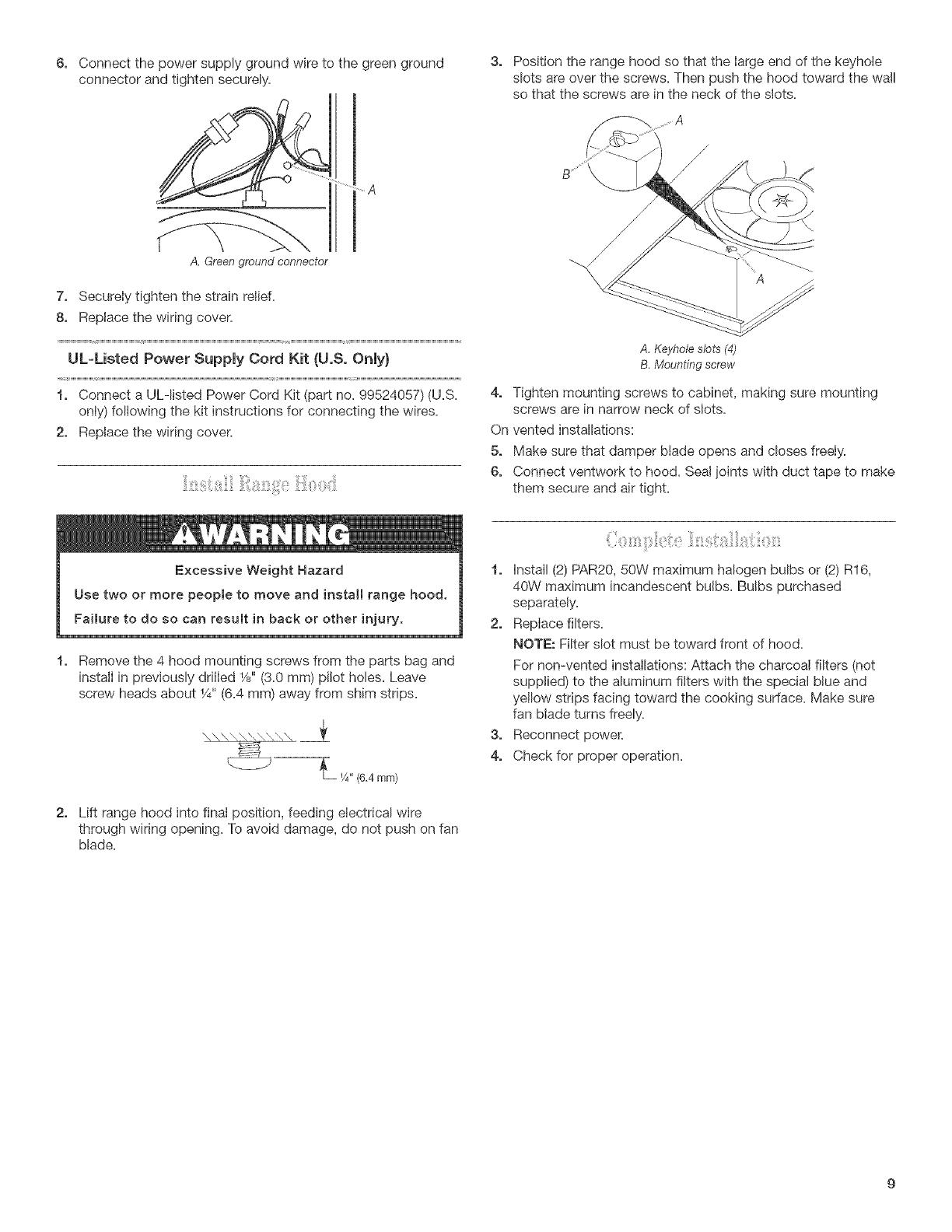
6, Connectthepowersupplygroundwiretothegreenground
connectorandtightensecurely.
3, Positiontherangehoodsothatthelargeendofthekeyhole
slotsareoverthescrews.Thenpushthehoodtowardthewall
sothatthescrewsareintheneckoftheslots.
.... A
A. Green ground connector
7, Securely tighten the strain relief.
8, Replace the wiring cover.
UL-Listed Power Supply Cord Kit {U,S, Only}
1, Connect a ULqisted Power Cord Kit (part no. 99524057) (U.S.
only) following the kit instructions for connecting the wires.
2, Replace the wiring cover.
A, Keyhole slots (4)
B. Mounting screw
4, Tighten mounting screws to cabinet, making sure mounting
screws are in narrow neck of slots.
On vented installations:
5, Make sure that damper blade opens and closes freely.
6, Connect ventwork to hood. Sea! ioints with duct tape to make
them secure and air tight.
Remove the 4 hood mounting screws from the parts bag and
install in previously drilled 1/8"(3.0 mm) pilot holes. Leave
screw heads about 1/4"(6.4 mm) away from shim strips.
1, install (2) PAR20, 50W maximum halogen bulbs or (2) R16,
40W maximum incandescent bulbs. Bulbs purchased
separately.
2, Replace filters.
NOTE: Filter slot must be toward front of hood.
For non-vented installations: Attach the charcoal filters (not
supplied) to the aluminum filters with the special blue and
yellow strips facing toward the cooking surface. Make sure
fan blade turns freely.
3, Reconnect power.
4, Check for proper operation.
2, Lift range hood into final position, feeding electrical wire
through wiring opening. To avoid damage, do not push on fan
blade.
RANGEHOODUSE RAN( EHOODCARE
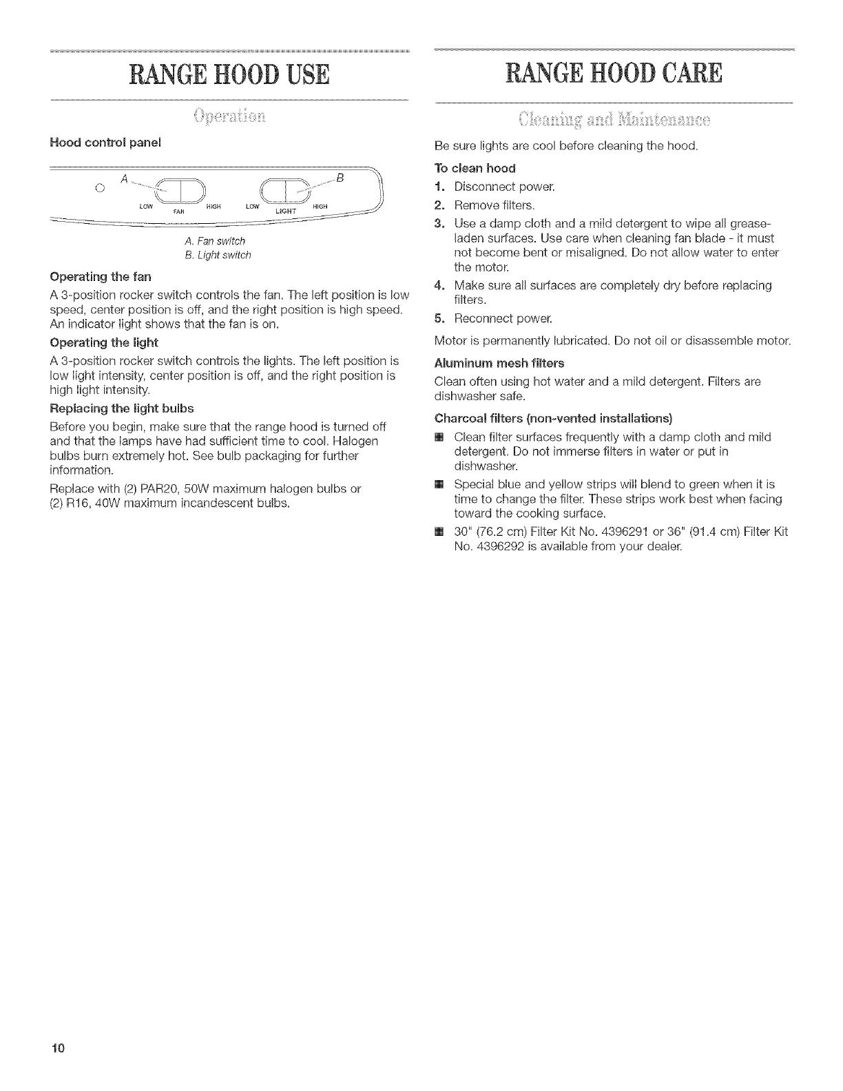
Hood control panel
0 A --% ....................B
HIGH LO
A. Fanswitch
B.Lightswitch
Operating the fan
A 3-position rocker switch controls the fan. The left position is low
speed, center position is off, and the right position is high speed.
An indicator light shows that the fan is on.
Operating the _ight
A 3-position rocker switch controls the lights. The left position is
low light intensity, center position is off, and the right position is
high light intensity.
Replacing the light bulbs
Before you begin, make sure that the range hood is turned off
and that the lamps have had sufficient time to cool. Halogen
bulbs burn extremely hot. See bulb packaging for further
information.
Replace with (2) PAR20, 50W maximum halogen bulbs or
(2) R16, 40W maximum incandescent bulbs.
Be sure lights are cool before cleaning the hood.
To clean hood
t, Disconnect power.
2, Remove filters.
3, Use a damp cloth and a mild detergent to wipe all grease-
laden surfaces. Use care when cleaning fan blade - it must
not become bent or misaligned. Do not allow water to enter
the motor.
4, Make sure all surfaces are completely dry before replacing
filters.
5, Reconnect power.
Motor is permanently lubricated. Do not oil or disassemble motor.
A_uminum mesh filters
Clean often using hot water and a mild detergent. Filters are
dishwasher safe.
Charcoal fiRers (non-vented installations)
[] Clean filter surfaces frequently with a damp cloth and mild
detergent. Do not immerse filters in water or put in
dishwasher.
[] Special blue and yellow strips will blend to green when it is
time to change the filter. These strips work best when facing
toward the cooking surface.
[] 30" (76.2 cm) Filter Kit No. 4396291 or 36" (91.4 cm) Filter Kit
No. 4396292 is available from your dealer.
t0
REQUESTINGASSISTANCEORSERVICE
if you need assistance or service in U.S.A.
Ca[[ the Whirtpoo_ Customer interaction Center toll=free at
1-800-253-1301o Our consultants are available to assist you,
When calling: Please know the purchase date, and the complete
model and serial number of your appliance This information wilI
help us better respond to your request.
Our consultants provide assistance with:
[] Features and specifications on our full Iine of appliances
[] Installation information
[] Use and maintenance procedures
[] Accessory and repair parts sales
[] Specialized customer assistance (Spanish speaking, hearing
impaired, limited vision, etc.)
[] Referrals to Iocal dealers, service companies, and repair parts
distributors
Whirlpool designated service technicians are trained to fulfill the
product warranty and provide after-warranty service, anywhere in
the United States.
To locate the designated service company in your area, you can
also look in your telephone directory Yellow Pages.
If you need replacement parts
If you need to order replacement parts, we recommend that you
use only factory-authorized parts. These parts will fit right and
work right, because they are made to the same exacting specifi-
cations used to build every new Whirlpool appliance.
To locate factory-authorized parts in your area, call our Customer
Interaction Center telephone number, your nearest authorized
service center, or 1-800-442-1111.
For further assistance
If you need further assistance, you can write to Whirlpool with any
questions or concerns at:
Customer Interaction Center
c/o Correspondence Dept.
2000 North M-63
Benton Harbor, MI 49022-2692
Please include a daytime phone number in your correspondence.
if you need assistance or service in Canada
For product related questions, please cail the Whirlpool Canada
LR Customer Interaction Center toll free: 1-800=461=5681
Monday to Friday 8:00 a.m. - 6:00 p.m. (EST).
Saturday 8:30 a.m. - 4:30 p.m. (EST).
Our consultants provide assistance with:
[] Features and specifications on our full line of appliances.
[] Referrals to Iocal dealers.
For parts, accessories and service in Canada
Call 1=800-807=6777° Whirlpool Canada LR designated service
technicians are trained to fulfill the product warranty and provide
after-warranty service, anywhere in Canada.
For further assistance
If you need further assistance, you can write to Whirlpool Canada
LR with any questions or concerns at:
Customer Interaction Center
Whirlpool Canada, LR
1901 Minnesota Court
Mississauga, Ontario L5N 3A7
Please include a daytime phone number in your correspondence.
11

RANGEHOODWARRANTY
For one year from the date of purchase, when this appliance is operated and maintained according to instructions attached to or
furnished with the product, Whirlpool Corporation will pay for labor and any parts of your range hood, except light bulbs and filters,
which are defective in materials or workmanship.
WhirmpoomCorporation will not pay for:
1, Service calls to correct the installation of your appliance, to instruct you how to use your appliance, to replace house fuses or
correct house wiring, or to replace owner-accessible light bulbs and filters.
2, Consumable parts such as light bulbs and filters.
3, Repairs when your appliance is used in other than normal, single-family household use.
4, Pickup and delivery. Your appliance is designed to be repaired in the home.
5, Damage resulting from accident, alteration, misuse, abuse, fire, flood, improper installation, acts of God or use of products not
approved by Whirlpool Corporation or Whirlpool Canada LR
WHIRLPOOL CORPORATION AND WHIRLPOOL CANADA LP. SHALL NOT BE LIABLE FOR INCIDENTAL
OR CONSEQUENTIAL DAMAGES,
Some states or provinces do not allow the exclusion or limitation of incidental of consequential damages, so this exclusion or limitation
may not apply to you. This warranty gives you specific legal rights and you may also have other rights which may vary from state to
state or province to province.
Outside the 50 United States and Canada, this warranty does not apply. Contact your authorized Whirmpoomdeamerto determine
if another warranty, applies,
If you need service, see the "Requesting Assistance or Service" section or call the Whirlpool Customer Interaction Center,
1_800-253-1301 (toll-free), from anywhere in the U.S.A. For parts and service in Canada, please call 1-800_807-6777. For product
related questions in Canada, please call 1_800-461_5681.
Keep this book and your samesslip together for future
reference, You must provide proof of purchase or installation
date for in-warranty service,
Write down the following information about your appliance to
better help you obtain assistance or service if you ever need it.
You will need to know your complete model number and seria!
number. You can find this information on the model and serial
number label/plate, located on your appliance.
Dealer name
Address
Phone number
ModeB number
Serial number
Purchase date
t2
/