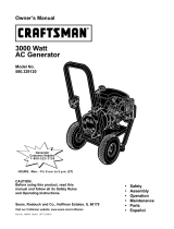
Craftsman 580.327750 Owner's manual

Category
Power generators
Type
Owner's manual

This manual is also suitable for

Owner's
anuam
®
120 VOLT
2500 WATT
AC
RATO
MODEL NO.
580.327750
LU
a
0
0 8
_03
0
r_
,o
o_
o_,_
z_- z
_=_ (.9LLI..... -4"--m
OOj_
o
m
CAUTION: Before using this
product, read this manual and
follow all Safety Rules and
Operating Instructions.
GENERATOR
CUSTOMER
HELPLINE
1_800-222-3136
HOURS: Mon. - Fri. 8 a.m. to 5 p.m. (CST)
SEARS. ROEBUCK and CO., Hoffman Estates, IL 60179 U.S.A.
Partr',lo.B2418 REV._3/12/98
SAFETYRULES.............. INSIDECOVER
MAINTENANCEAGREEMENT................. 10
PRODUCTSPECIFICATIONS.............. 10
WARRANTY............................ 2
OPERATION......................... 4-9
MAINTENANCE........................ 9-12
SERVICEANDADJUSTMENTS .......... 12-13
SERVICERECOMMENDATIONS........... 12
TROUBLESHOOTINGPOINTS ............. 14
WIRINGDIAGRAM...................... 15
REPAIRPARTS...................... 16-37
EMISSIONSWARRANTY................ 38-39
PARTSORDERING............. BACKCOVER
LIMITED ONE YEAR WARRANTY CRAFTSMAN GENERATORS
SEARS warrants to the original purchaser that the alternator and engine for its portable generator will be free from
defects in materials or'workmanship for the items and period set forth below from the date of original purchase, this
warranty is not trasnferable.
CONSUMER* COMMERCIAL*
Alternator 1 year' 90 Days
Engine 1 year 90 Days
NOTE: For the purpose of this warranty "Consumer Use" means personal residential household and emergency use
by original purchaser, not to be used as a primary source of power: "Commercial Use" means all other uses, includ-
ing rental, construction, commercial, primary source of residential household power and income producing purposes°
Once a generator has experienced commercial use, it shall thereafter be considered a commercial use generator for
the purpose of this warranty.
During said warranty period, SEARS wit!, at its option, repair or replace any part which, upon examinations by
SEARS, is found to be defective under normal use and service_** Starting batteries and expendable items such as
spark plugs and air filters, which become worn during normal use are not warranted by SEARS. All transportation
costs under warranty, including return to the factory if necessary, are to be borne by the pruchaser and prepaid by
him° This warranty does not cover normal maintenance and service and does not apply to a generator set, alternator
or engine, or parts which have been subjected to improper or unauthorized installation or alteration, misuse, negli-
gence, accident, overloading, overspeeding, improper maintenance, repair or storage so as, in SEAR's judgment, to
adversely affect its performance and reliability°
**NORMAL WEAR: As with all mechanical devices, engines need periodic parts service and replacement to perform
well. This warranty will not cover repair when normal use has exhausted the life of a part or engine,.
THERE tS NO OTHER EXPRESS WARRANTY. SEARS HEREBY DISCLAIMS ANY AND ALL IMPLIED WARRAN-
TIES, INCLUDING BUT NOT LIMITED TO THOSE OF MERCHANTABILITY AND FITNESS FOR A PARTICULAR
PURPOSE TO THE EXTENT PERMITTED BY LAW° THE DURATION OF ANY IMPLIED WARRANTIES WHICH
CANNOT BE DISCLAIMED IS LIMITED TO THE TIME PERIOD AS SPECIFIED IN THE EXPRESS WARRANTY.
LIABILITY FOR CONSEQUENTIAL, INCIDENTAL, OR SPECIAL DAMAGES UNDER ANY AND ALL WARRANTIES
IS EXCLUDED° Some states do not allow limitations on how long an implied warranty lasts, or the exclusion or limita-
tion of incidental or'consequential damages, so the above limitations or' exclusions may not apply to you_ This war-
ranty gives you specific legal rights and you may also have other rights, which vary from state to state.
For service, see your nearest SEARS authorized warranty service facility. Warranty service can be performed only by
a SEARS authorized service facility° This warranty will not apply to service at any other facility° At the time of request-
ing warranty service, evidence of original purchase date must be presented.
SEARS, ROEBUCK and CO., Hoffman Estates, IL 60719 U.S.A.
2
CAUTION:ALWAYSDISCONNECTSPARKPLUGWIREAND PLACEWIREWHEREIT CAN- F_
NOTCONTACTSPARKPLUG,TO PREVENTACCIDENTALSTARTINGWHENSETTINGUP,
TRANSPORTING,ADJUSTING,ORMAKING REPAIRSTOYOURGENERATOR
IMPORTANT
THISGENERATORIS DESIGNEDFOROUTDOORUSEONLY.USINGTHIS GENERATORINSIDEANY BUILDINGORENCLOSURE,
INCLUDINGTHEGENERATORCOMPARTMENTOFA RECREATIONALVEHICLE(RV), IS DANGEROUS,FIREORANEXPLOSIONMAY
RESULT.NOUSERPERFORMEDMODIFICATIONS,INCLUDINGVENTINGOFEXHAUSTAND!ORCOOLINGVENTILATION,WILL ELiM-
INATETHE DANGER°
If this unit isusedfor backup power in the event of a utility
powerfailure, takethefollowing steps: BEFORECONNECT-
INGTHEGENERATORTOAN ELECTRICALSYSTEM,OPEN
THEMAINCIRCUITBREAKERORMAIN SWITCHSERVIC-
INGTHESYSTEMTOISOLATETHEGENERATORFROM
THEELECTRICUTILITY.FAILURETOISOLATETHE GENER-
ATORANDUTILITYSYSTEMSMAY RESULTIN DAMAGE
TOTHEGENERATORAND MAYALSO RESULTIN INJURY
ORDEATHTOELECTRICUTILITYWORKERSDUETO
BACKFEEDOFELECTRICALENERGY.
This generatorproduces dangerously high voltage that can
causeextremely hazardouselectrical shock.. Avoid contact
with barewires,terminals, etc. Neverpermit any unqualified
personto operateor servicethe generator.
- DONOToperatethis equipmentin the rain, while standing
in water,while barefoot,or while handsor feet are wet..Dan-
gerous electricalshock will result.
, TheNational ElectricCoderequiresthe frame and external
electrically conductive parts of the generator be properly
connectedto an approvedearth ground° Localelectrical
codesmay also requireproper grounding of the generator°
Consultwith a localelectricianfor grounding requirements
in your area.
Theengineexhaustfromthisproductcontainschemicals
knowntotheStateofCaliforniatocausecancer,bidhdefects H
GasolineishighlyFLAMMABLEand its vaporsare EXPLO-
SIVE.Donot permit smoking, open flames, sparksor heat
in the vicinity while handling gasoline..Avoid spilling gaso-
line ona hot engine..Complywith alt lawsregulating storage
and handlingor gasoline_.
Never addfuel whileunit is running
° Donot overfill thefuel tank.Always allow room for fuel
expansion. If tank is overfilled, fuel can overflow onto a hot
engine and cause FIREor an EXPLOSION..
Drainall gasolinefrom tank before transporting yourgener-
ator insideyour car or other vehicle.
, Never store generatorwith fuel in tank where gasoline
vapors might reachan open flame or spark or pilot light (as
on afurnace, water heateror clothes dryer). FIREor AN
EXPLOSIONmight resulL
Allow at least2 feet of clearanceon all sides of generator,
evenwhile operating unit outdoors, or you could damage
the unit..
Generatorexhaustgases contain DEADLYcarbon monoxide
gas_This dangerousgas, if breathed in sufficient concentra-
tions, cancauseunconsciousness or evendeath_Operate
this equipment outdoors only in the open air whereade-
quate ventilation is available.
Donot insert anyobject through cooling slots ofthe engine-
generator°You coulddamagethe unit or injure yourself.
DONOTattempt to changethe engine governedspeed.Fac-
tory settings are correct when you receivethe unit..Exces-
sively high engine speeds may result in injury or damageto
equipment.
o DONOT usethe unit if it has beendamaged..Repairor
replaceall damagedor defective components before you
run the unit.
Do not permit childrento operate or servicethe unit..
= Readyour Owner'sManual carefully..Only personswho are
familiar with these safety rulesand havebeen properly
instructed inthe use of this product should be permittedto
usethe product.,
Note:IntheStateofCaliforniaasparkarrestorisrequiredbylaw(Sec-
tion4442oftheCaliforniaPublicResourcesCode).,Otherstatesmay
havesimilartaws_Federallawsapplyonfedera!lands,
,t_ LOOK FOR THIS SYMBOL TO POINT OUT IMPORTANT SAFETY PRECAUTIONS.IT MEANS "ATTENTION!!! BECOME ALERT!!! YOUR SAFETY IS INVOLVED!!!"
3
Your AC generator was completely assernsble at the fac-
tory. It is ready for use after it has been properly serviced
with the recommended lubricating oil and fuel.,
IF YOU HAVE ANY PROBLEMS WITH THE ASSEMBLY
OF YOUR GENERATOR, PLEASE CALL THE GENERA-
TOR HELPLINE AT 1-800_222-3136.
IMPORTANT: ANY ATTEMPT TO RUN THE ENGINE
BEFORE tT HAS BEEN SERVICED WITH THE RECOM-
MENDED OIL WILL RESULT IN AN ENGINE FAILURE..
TO
Q
REMOVE GENERATOR FROM CARTON
Set the carton on a flat rigidsurface with "THIS SIDE
UP" arrows pointing upward.
° Carefully open the top flaps of shipping carton_
° Cut down corners at one end of shipping carton and
lay that side of carton down flat.
- Remove packing material, carton fillers, etc_.
° Remove the generator from the shipping carton°
TO ADJUST HANDLE GUIDE
Yourgenerator is equipped with a wheel kit for easy man-
ueveringo After' you remove the generator from the carton
Lifthandle into upright position and push the black slides
down to hold the handle in position. The handle may be
lowered for easier' storage.
CORD SETS AND CONNECTOR PLUGS
120 VOLT CORD SETS
use only high quality, wefl-insutated, extension cords with
the generator's 120-volt type electrical receptacle&
Each receptacle of this pair is protected against overload
by a single 20-amp push-to-reset type of circuit breaker°
Use each receptacle to operate 120 volts, single phase
60 Hz, A C electrical loads requiring up to 2400 watts (2.4
kW) at 20 amps of current_
!
Figure-1
Check the ratings of all extension cords before you use
them Extension cord sets used should be rated 125 volts
at 20 AC amps or greater' for' most electrical devices..
Some devices, however, may not require this type of
extension cord° Check the owner's manual of those
devices for the manufacturer's recommendations.
CAUTION:Althougheachreceptacleis ratedfor120
voltsat 20 amps(2400 wattsor2A KW),the generator
israted for a totalof 2500 watts.Poweringloadsthat
exceedthewattagecapacityofthe generatorcandam-
age itor causeseriousinjuries.Thetotal loadswith
120 voltspoweredthoughthesereceptaclesshouldnot
exceed20 amps.
Keep extension cords as short as possible, preferably
less than 15 feet long to prevent voltage drop and possi-
bly overheating of wires.
12 VOLTS DC 10 AMP BATTERY CHARGE OUTLET
Figure-2
The 12 VOLT DC outlet has a unique configuration that
will only allow the 12 volt wire harness to be inserted,
When the 12 volt harness is properly inserted the red wire
wil! be positive 12 volts and the blackwire will be negative_
DO NOT modify any plug to make it fit this outlet or dam-
age to the generator may result.
4
KNOW YOUR GENERATOR
Read the owner's manual and safety rules before operating your generator. Compare the illustrations with your Genera-
tor to familiarize yourself with the locations of various controls and adjustments. Save this manual for future reference_
GUIDE HANDLE
AIR CLEANER
HEATSHIELD AND
MUFFLER
GAS CAP
CHOKE
ON/OFFLEVEL
5 HP ENGINE
OIL FILL
OIL DRAIN
CIRCUIT BREAKERS,
BATTERY CHARGE
RECEPTACLE, AND
DUPLEX RECEPTACLE
120 VOLT RECEPTACLES. May be used to supply elec-
trical power for the operation of 120 volts at 20 amps AC,
single phase, 60 Hz,.This may be used for AC electrical
lighting, appliance, tool and motor loads.
BATTERY CHARGE RECEPTACLE. May be used to
supply electrical power to charge 12 volt batteries.
CIRCUIT BREAKERS (AC and DC), Each receptacle is
provided with a circuit breaker to protect the generator
against electrical overload° Breakers are "push to reset"
type
AIR CLEANER. Filters intake air as it is drawn into the
engine
5.0 H.P. HONDA ENGINE. Provides the power needed to
generate 2500 watts of AC output,
RECOIL STARTER. Used for starting the engine,
ON/OFF LEVER. Set this lever to "ON" before using
recoil starter Set lever to "OFF" to switch engine off.
Located on the engine block.
FUEL TANK. Tank holds 18 quarts of unleaded gasoline.
SPARK ARRESTOR MUFFLER. Exhaust muffler lowers
engine noise and is equipped with a spark arrestor
screen°
CHOKE SWITCH. Used when starting a cold engine.
HOW TO USE YOUR GENERATOR. IF YOU HAVE ANY
PROBLEMS operating your Generator, please call the
Generator helpline at 1-800-222-3136.
5
GROUNDING THE GENERATOR
The National Electrical Code requires that the frame and
external electrically conductive parts of this generator by
properly connected to an approved earth ground. Local
electrical codes may also require proper grounding of the
unit. For that purpose, a GROUND LUG is provided (Fig-
ure-3).,
Generally, connecting a No. 12 AWG (American Wire
Gauge) stranded copper wire to the grounding lug and to
an earth-driven copper or brass grounding rod (electrode)
provides adequate protection against electrical shock.
However, tocaf codes may very widely. Consult with a
local electrician for grounding requirements in your area.
Proper grounding of generator will help prevent electricat
shock in the event of a ground fault condition in the gener-
ator or in connected electrical devices. Proper grounding
also helps dissipate static electricity, which often builds up
in ungrounded devices.,
IF YOU HAVE ANY PROBLEMS OPERATING YOUR
GENERATOR, PLEASE CALL THE GENERATOR
HELPLINE AT 1-800-222-3136.,
t_12 AWG STRANDEO
GROUNDING ROD
Pour oilinto the oil fill opening until oil reaches FULL
mark on the dipstick. DO NOT OVERFILL. Oii capac-
ity of engine is 0.61 US quarts.
o Install oil dipstick, hand tighten securely
Figure-4
CAUTION:ANYATTEMPTTOCRANKORSTARTTHE
ENGINEBEFOREIT HASBEENPROPERLYSER-
VICEDWITH THERECOMMENDEDOILRESULTSIN
ANENGINEFAILURE.
Note: When adding oil to the engine crankcase in the
future, use only high quality detergent oit rated with API
service classification SF, SG, or SH rated SAE 30 weighL
Use no special additives. Although multi-viscosity oils
(5W30) improve starting in cold weather, multi-viscosity
oilswill result in increased oil consumption when used
above 32° E It will be necessary to check "yourengine oil
level more frequently to avoid possible damage from run-
ning low on oil Oil sump capacity is 0.61 US quarts. DO
NOT use 10W-40.
FLgure-3
BEFORE STARTING THE GENERATOR
Tooperatethe engtne youwillneed todothefollowing:
ENGINE OIL,
Important: To avoid engine damage never run engine
unless:
Oil level is between =Full" and "Add" marks on the dip-
stick,.
Oil fillplug is tightened securely intooi! fill tube or
hole.
ADD OIL
Place generator on a level surface.
Clean area around oilfill and remove oildipstick.
Wipe dipstick clean,.
colder ._ 32° _LI=.- warmer
5W30 SAE30
ADD GASOLINE
Use regular UNLEADED gasoline with the Generator
engine. DO NOT USE PREMIUM GASOLINE. DO
NOT MIX OIL WITH GASOLINE°
- Clean area around fuel fill cap, remove cap°
° Add "UNLEADED" regular gasoline, slowly to fuel
tank. BE CAREFUL NOT TO OVERFILL° Allow about
1/4-inch of tank space for expansion.
tnstaflfuel cap and wipe up any spilted gasoline.
Important: It is important to prevent gum deposits from
forming in essential fuel system parts such as the carbu-
retor, fuel filter, fuei hose or tank during storage. Also,
experience indicates that alcohol-blended fuels (catled
gasohol,ethanolormethanol)canattractmoisturewhich
leadstoseparationandformationofacidsduringstorage..
Acidicgascandamagethefuelsystemofanengine
whileinstorage.Toavoidengineproblemswhenusing
gasohoI,emptythefuelsystembeforestorageof 30 days
or longer., See "Storage" on Page 13. Never use engine or
carburetor cleaner products in the fuel tank or permanent
damage may occur.
NOTE: DO NOT USE GASOLINE CONTAINING METHA-
NOL (WOOD ALCOHOL). You can use gasolines contain-
ing 10% ethanol or grain alcohol See "Storage" for more
information°
CAUTION:DONOTOVERFILLTHEFUELTANK.
ALWAYSALLOWROOMFORFUELEXPANSION.
o Pul! engine CHOKE LEVER (Figure-6) to "Full
Choke Position",.
o Grasp start grip and pull slowly until you feel some
resistance., Then pull cord out with rapid full arm
stroke. Let rope return slowly. Do not let rope "snap
back" against the starter grip.
. When engine starts, move choke lever to "1/2 Choke
Position until the engine runs smoothly and then to
"No Choke Position". if engine falters, move choke
lever to'"112 Choke Position" until the engine runs
smoothly and then to "No Choke Position"..
Note: If engine fails to start after 3 pulls, move the coke
lever to "No Choke Position" and pull starter rope again.
Note: If engine fires, but does not continue to run, move
choke lever to "Full Choke Position" and repeat starting
instructions..
WARNING:NEVERFILLFUELTANKINDOORS.
NEVERFILLFUELTANKWHENENGINEIS RUN-
NINGORHOT,DONOTLIGHTACIGARETOR
SMOKEWHENFILLINGFUELTANK.
TO START THE ENGINE
WARNING:NEVERSTART,ORSTOP,THE
ENGINE-GENERATORWITHELECTRICALLOADS
CONNECTEDTOTHE RECEPTACLESWITHTHE
CONNECTEDDEVICESTURNEDON.
Figure-5
Unplug all electrical loads from generator receptacles
before starting the engine_ NEVER start or stop
engine with electrical devices plugged into the panel
receptacles and turned on.
° Set ON/OFF LEVER to ON (Figure-5).
Figure-6
CONNECTING ELECTRICAL LOADS
o Let engine stabilize and warm up for a few minutes
after starting..
Use this generator to operate 120 volt, single phase,
60 Hz, AC lighting, appliance, tool and motor loads,.
° DO NOT connect 240 volts to 120 voIts duplex recep-
tacles.
DO NOT connect 3-phase loads to panel receptacles.
° DO NOT connect any 50 Hz loads to the generator.
o Plug in and turn on the desired 120 volts single
phase, 60 HZ, AC electrical loads. DO NOT OVER-
LOAD THE GENERATOR Add up the rated watts (or
amps) of all loads to be connected at one time.. This
total should not be greater than the rated wattage/
amperage capacity of the generator. See "Do Not
Overload the Generator" on Page 8.
STOPPING THE ENGINE
° Unplug all electrical loads from generator panel
receptacles° Never start or"stop engine with electrical
devices plugged in and turned on.
Let engine run at no-load for' several minutes to stabi-
lize the internal temperatures of engine and genera-
tort
Move On/Off Switch to Off position.
CHARGING A BATTERY
Your generator has the capability of recharging a dis-
charged, 12-volt automotive or utility style storage battery°
Do not use the unit to charge any 6-volt batteries° Do not
use the unit to crank an engine having a discharged bat-
tery To recharge 12-volt batteries, proceed as follows:
° Check fluid level in all battery cells.. If necessary, add
ONLY distilled water to cover separators in battery
cells. DO NOT USE TAP WATER.
if the battery is equipped with vent caps, make sure
they are installed and are tight.
° If necessary, clean battery posts or terminals°
° Connect battery charge cable connector' plug to panel
receptacle (Figure-2, Page 4) identified by the words
"12-VOLT DoC."
Connect battery charge cable clamp with red handle
to battery post or terminal indicated by a POSITIVE,
POS,or (+).
° Connect battery charge cable clamp with black han-
" die to battery post or terminal indicated by a NEGA-
TIVE, NEG, or (-).
Start engine (see "Starting the Engine" on Page 7).
Let the engine run while battery recharges.
, When battery has charged, shut down engine (see
"Stopping the Engine" above).
Note: Use an automotive hydrometer to test battery state
of charge and condition_ Follow the hydrometer manufac-
turer's instructions carefully. Generally, a battery is con*
sidered to be at 100% state of charge when specific
gravity of its fluid (as measured by hydrometer) is 1o260.
LOW OIL PRESSURE SHUTDOWN SYSTEM
The engine is equipped with a low oil pressure sensor
that shuts down the engine autornaticaIly when the oil
pressure drops below 6 psL If the engine shuts down by
itsetf and the fuel tank has enough gasoline, check
engine oil level.
INITIAL STARTUP
A delay in the shutdown system allows oil pressure to
build during starting., The delay allows the engine to run
for about 10 seconds before sensing oil pressure.
RESTARTING
If you try to restart the engine within 5 second after it
shuts dowrY,the engine may not start_ The system needs
5 to 10 seconds to reseL
If you do restart the engine after such a shutdown
and have not corrected the low oil pressure, the
engine runs for about 10 seconds as described above
and then stops.
DON'T OVERLOAD THE GENERATOR
Overloading a generator in excess of its rated wattage
capacity can result in damage to the generator and to
connected electrical devices. Observe the following, to
prevent overloading the unit:
= Add up the total 'wattage of afl electrical devices to be
connected at one time° This total should NOT be
greater than the generator's wattage capacity_
= The rated wattage of lights can be taken from light
bulbs. The rated wattage of tools, appliances and
motors can usually be found on a data plate or decal
affixed to the device°
° if the appliance, tool or motor does not give wattage,
multiply volts times ampere rating to determine watts
(volts x amps = watts).
, Some electric motors, such as induction types,
require about two and a half times more watts of
power' for starting than for running° This surge of
power lasts only a few second when starting such
motors. Make sure you allow for'this high starting
wattage when selecting electrical devices to connect
to your generator. First, figure the watts needed to
start the largest motor. Add to that figure the running
watts of all other connected loadso
The Wattage Reference Guide is provided to assist you in
determining how many items your generator' can operate
at one time.
WATTAGE REFERENCE GUIDE
RUNNING ELECTRICALDEVICE RUNNING ELECTRICALDEVICE RUNNING
ELECTRICALDEVICE
WATTS WATTS WATTS
L_L ..._..... LLL _ :; :; :;:; :: ...................
*AirConditioner 1700 ElectricSkillet I250 OilFiredSpaceHeater 400
(12,000btu) (85,000Btu)
BatteryCharger 500 *FurnaceFan(113HP) 1200 OilFiredSpaceHeater 225
(20amp) (30,000Btu)
BeltSander t000 HairDryer 1200 *PaintSprayer, 600
Airless(1/3HP)
== ;,,. ..........
ChainSaw t200 HandDrill(1") 1100 PaintSprayer, 150
Airless(handheld)
CircularSaw(6 112") 800to 1000 HandDdlf(1/2") 750to 1000 Radio 50to 200
CoffeeMaker 1000 HandDrill(3/8") 500 *Refrigerator 600
J r
*Compressor(I HP) 2000 HandDrill(1/4") 250 SlowCooker 200
*Compressor(3/4HP) 1800 HedgeTrimmer 450 *SubmersiblePump 2800
(I-1/2 HP)
*Compressor(i/2 HP) 1400 *JetPomp 800 *SubmersiblePump 2000
(1 HP)
CurlingIron 700 LawnMower 1200 *SubmersiblePump t500
(1/2HP)
"DeepFreeze 500 LightBu]b 700 SumpPump 600
DiscSander(9") t200 MicrowaveOvern 700 *TableSaw(10") 1750to2000
EdgeTrimmer 500 *MilkCooler 1100 Television(10") 200to 500
............................................................... , ....... i ............
ElectricNailGun 1200 OilBurneronFurnace 300 WeedTrimmer 500
.... ..... J , ..........,, ,
ElectricRange 1500 OilFiredSpaceHeater 400
(oneelement) (140,000Btu)
"Allow 2-1/2 times the Iisted watts for starting these device&
CUSTOMER RESPONSIBILITIES
GENERAL RECOMMENDATIONS
The Owner/Operator is responsible for making sure that
all periodic maintenance tasks are completed on a timely
basis; that all discrepancies are corrected; and that the
unit is kept clean and properly stored. Never operate a
damaged or defective generator°
The warranty of the Generator does not cover items that
have been subjected to operator abuse or negligence.. To
receive full value from the warranty, operator must main-
tain Generator as instructed in this manual.
Some adjustments will need to be made periodically to
properly maintain your Generator.
All adjustments in the Service and Adjustments section of
this manual should be made at least once each season..
Follow the recommendations in the "Service Recommen-
dation" Table on Page 12..
PRODUCT SPECIFICATIONS
Generator Specifications
Rated Maximum Power
Rated Voltage
Rated Maximum
Load Current
Rate Frequency
Phase
2500 (2.5 KW)
12 VDC and 120 Volts AC
20.8 AC amperes
60 Hz at 3600 rpm
Single Phase
Engine Specifications
Rated Horsepower 5,0 at 3600 rpm
Spark Plug NGK BPR6ES
or equivalent
Set Gap To: 0.030 inch (0.76mm)
Gasoline Capacity: 1.8 quarts
Oil (Q.61 US quarls capacity): SAE 30 weight
Solid State Ignition 0.0125 inch
Air Gap
Should you experience any problem you cannot easily
remedy, please contact your nearest Sears Service Cen-
terJDepartment or call the 1-800 number listed on the
front of this manuat we have competent, well-trained
technicians and the proper toolsto service or repair' this
unit,.
Please read and retain tn_smanual, the instructions will
enable you to assemble and maintain your' generator
properly. Always observe the "SAFETY RULES'L
Once a year you should clean or' replace the spark plug
and replace the air filter A new spark plug and clean air
filter assure proper fuel-air mixture and help your engine
run better and last longer
MAINTENANCE AGREEMENT
A Sears Maintenance Agreement is available on this
product,,
CUSTOMER RESPONSIBILITIES
Read and observe the safety rules.
Follow regular schedule in maintaining, caring for and
using your generator.
Follow the instructions under "Maintenance" and "Stor-
age" sections of this Owner's Manual.
NOTE: Your generator is equipped with a spark arrestor
muffler: The spark arrestor must be maintained in effec-
tive working order by the owner/operator_ In the State of
California a spark arrestor is required by law (Section
4442 of the California Public Resources Code)_ Other
states may have similar' laws. Federal laws apply on fed-
eral lands°
CAUTION:DISCONNECTSPARKPLUGWIRE
FROMSPARKPLUGANDPLACEWIREWHEREIT
CANNOT'COMEIN CONTACIWITHYOURSPARK
PLUGBEFOREWORKINGONYOURGENERATOR.
GENERATOR MAINTENANCE
Generator maintenance consists of keeping the unit clean
and dry Operate and store the unit in a clean, dry envi-
ronment where it wilt not be exposed to excessive dust,
dirt, moisture or any corrosive vapors,, Cooling air slots in
the generator must not become clogged with snow,
leaves, or any other foreign material.
Check the cleanliness of the generator frequently and
clean when dust, dirt, oi!, moisture or other foreign sub-
stances are visible on itsexterior surface,.
Note: We DO NOT recommend using a garden hose to
clean the generator_ Water can enter-the engine fuel sys-
tem and cause problems,, tn addition, ff water enters the
generator through cooling air slots, some of the water will
be retained in void and cracks of the rotor and stator
winding insulation, Water and dirt buildup on the genera-
tor internal windings will eventually decrease the insula-
tion resistance of these windings°
To clean the Generator:
* Use a damp cloth to wipe exterior surfaces cfean.
° A soft bristle brush may be used to loosen caked on
dirt, oil, etc.
. A vacuum cleaner may be used to pick up loose dirt
and debris.
° Low pressure air (not to exceed 25 psi) may be used
to blow away dirt,, inspect cooling air' slots and open-
ings on the generator,, These openings must be kept
clean and unobstructed.
CAUTION:NEVERINSERTANY OBJECTORTOOL1
THROUGHTHE AIRCOOLINGSLOTS,EVENIF !
THE ENGINEIS NOTRUNNING.DAMAGETOTHEi
UNITORPERSONALINJURYMAYRESULT. J
10
ENGINEMAINTENANCE
CHECKING OIL LEVEL
Oii levet should be checked prior to each use or at least
every 5 hours of operation, Keep oil level maintained.
CHANGING ENGINE OIL
CAUTION:DISCONNECTSPARKPLUGWIRE
FROMSPARKPLUGAND KEEPITAWAYFROM
SPARKPLUG.DOTHIS EVERYTIMEYOUPER-
FORMANYMAINTENANCEONTHEENGINEOR
GENERATOR
Change oil after first 2 hours of operation, Change oil
every 25 hours thereafter., tf you are using your generator
under extremely dirty or dusty conditions, or in extremely
hot weather, change oil more often,
Change oil while engine is still warm from running, as fol-
lows:
o Clean area around oil drain plug (Figure-7).
o Remove oil drain plug and oil fill plug to drain oil.
o When oil has drained, install oil drain plug and tighten
securely°
° Insert a clean fill funnel and fill oil sump with recom-
mended oil until oil level is at point of overflowing.
POUR SLOWLY. (See "Before Starting the Engine"
on Page 6 for oil recommendations).,
Install the oil fill plug and tighten securely,
Wipe up any spilled oilo
° Replace spark plug if electrodes are pitted, burned or
porcelain is cracked° For replacement use NGK
BPR6ES only,
o Check electrode gap with wire feeler gauge and set
spark plug gap to 0.030 inch (0.76 mm) if necessary
(Figure-9).
SERVICE AIR CLEANER
Your engine will not run properly and may be damaged if
you run it using a dirty" air cleaner,,
Clean or replace the air cleaner once every 125 hours of
operation or once each year, whichever comes first.
Replace more often if operating under dirty or dusty con-
ditionso Replacements are available at your local Sears
Authorized Service Center.
To clean or replace the air cleaner, follow these steps:
° Push in on tabs and lift outside edge (Figure-8),
= Remove air cleaner cover carefully°
° Remove the air filter and examine itfor damage,
= Replace air filter if damaged or dirty.
° Reassemble all parts and replace cover_,
o Push tabs into slots until they %lick"o
F}gure-7
CLEAN SPARK PLUG
Change the spark plug every 100 hours of operation or
once each year, whichever comes first. This will help your
engine to start easier and run better. Replace with NGK
BPR6ES only,
. Clean area around spark plug,
° Remove and inspect spark plug.
Figure_8
REPLACE SPARK PLUG
Change the spark plug every 100 hours or operation or
once each year, whichever comes first. This will help your
engine to start easier and run better° Replace with NGK
BPR6ES or equivalent type spark plug, Set spark plug
gap to 0.030 inch (0,76mm)_
11
0030" FEELER GAUGE
(O,,76mm)
Figure-9
CLEAN SPARK ARRESTOR SCREEN
WARNING:LETTHEMUFFLERCOOLBEFORE
WORKINGONIT+CONTACTWITH AHOTMUF-
FLERORENGINECANCAUSESEVEREBURNS+
The engine exhaust muffler has a spark arrestor screen+
Inspect and clean the screen every 25 hours of operation
or once each year, whichever' comes first.
NOTE: Ifyou use your' generator on any forest-covered,
brush-covered or grass-covered unimproved land, it must
have a spark anestor.. The spark arrestor must be main-
tained in good condition by the ownedoperator+
Clean and inspect the spark arrestor as follows:
To remove the heat shield from the muffler (Figure-3),
remove the three bolts that connect the shield to the
muffler.
° Remove the phillips head screw that attaches the
spark arrestor screen.
Pull screen straight ouL
° Inspect screen and replace if torn, perforated or oth-
erwise damaged+ DO NOT USE a defective screen. If
the screen is not damaged, clean it with a commercial
solvent.
° Reattach the screen and the heat shield.
SERVICE RECOMMENDATIONS
Fillin DatesAsYouCompleteRegular HOURLYOPERATINGINTERVAL
Service
SERVICEDATES
Before Every25 Every50 Every100
MAINTENANCETASK EachUse Hoursor Hoursor Hoursor
Yearly Yearly Yearly
ENGINE X
Check011Level
................................ , ............ : ............. i, ......... L L ....
ChangeEngineOil* X**
ServiceAir+Cleaner X***
C{eardReplaceSparkPlug X
PrepareForStorage Prepareunitfor storageif_tistoremainidleforMORE
THAN30 DAYS
"Change oil after first 2 hours of operation, then after every 2 hours,
** Change sooner when operating under heavy Goador high ambient
temperature
"*'Clean more often under dirty or dusty conditions
ENGINE SPEED
Your generator engine runs at a constant speed+ This
constant operating speed is maintained by a mechanical,
flyweight type, fixed speed governor+ DO NOT try to
adjust the governed speed setting for' the following rea-
sons:
High engine speeds are dangerous and increase the
risk of personal injury or damage to equipment+
° Low engine speeds impose a heavy load on the
engine when sufficient engine power' is not available
and may shorten engine f_fe+
The generator will supply correct rated AC frequency
and voltage only at the proper speed+ Some con-
t2
nectedelectricaldevicescouldbedamagedby incor-
rectfrequencyand/orvoltage
ADJUSTING THE CARBURETOR
The carburetor of your generator is preset at the factory_
DO NOT TAMPER WITH THE CARBURETOR as this wilt
void the warranty for the emission control system. If you
think your carburetor needs adjusting, see your nearest
Sears Service dealer If your generator is to be used at
an elevation above 5,000 feet in attitude, consult with a
Sears Authorized Service Facility regarding high altitude
jetting changes. To improve engine performance, see
your nearest Sears Service dealer_
EMISSION CONTROL SYSTEM INFORMATION
Sources of Emissions. The combustion process pro-
duces carbon monoxide, oxides of nitrogen, and hydro.
carbons Control of hydrocarbons and oxides of nitrogen
is very important because, under certain conditions, they
react to form photochemical smog when subjected to
sunlight. Carbon monoxide does not react inthe same
way but it istoxic°
Honda uses lean carburetor settings and other systems to
reduce the emissions of carbon monoxide, oxides of nitro-
gen, and hydrocarbons.
The U.S. and California Clean Air Acts. EPA and Cali-
fornia regulations require all manufacturers to furnish writ-
ten instructions describing the operation and
maintenance of emission control systems,
Tampering and Altering. Tampering with or altering the
emission control system may increase emissions beyond
the legal limit. Among those acts that constitute tamper-
ingare:
o Removal or alteration of any part of the intake, fuel, or
exhaust systems
° Altering or defeating the governor linkage or speed
adjusting mechanism to cause to engine to operate
outside its design parameters.
Problems that may Affect Emissions. If you are aware
ofany of the following symptons, have your engine
inspected and repaired by you servicing dealer.
= Hard starting or stalling after starting
* Rough idle.
o Misfiring or backfiring under load
o Afterburning (backfidng)
GENERAL
The generator should be started at least once every
seven days and allowed to run at least 30 minutes_ If this
cannot be done and you must store the unit for more than
30 days, use the following information as a guide to pre-
pare itfor storage.
WARNING:NEVERSTOREENGINEWITH FUELiN
THETANKINDOORSORIN ENCLOSED,POORLY
VEHTILATEDAREAS,WHEREFUMESCAN
REACHANOPENFLAMESPARKORPILOTLIGHT
ASONAFURNACE,WATERHEATER,CLOTHES
DRYEROROTHERGASFURNACE.
To avoid engine problems, the fuel system should be
emptied before storage or 30 days or longer. Fo]low these
instructions
PROTECT FUEL SYSTEM:
Remove all gasoline from the fuel tank to prevent
gum deposits from forming on these parts and caus-
ing possible malfunction of engine
Run engine until engine stops from lack of fuel
WARNING:DRAINFUELINTOAPPROVEDCON-
TAINEROUTDOORS,AWAYFROMOPENFLAME
BESUREENGINEIS COOL°
LONG TERM STORAGE INSTRUCTIONS
It is important to prevent gum deposffs from forming in
essential fuel system parts such as the carburetor, fuel fil-
ter, fuel hose or tank during storage Experience indicates
that alcohol-blended fuels (called gasohol, ethanol or
methanol) can attract moisture which leads to separation
and formation of acids during storage. Acidic gas can
damage the fuel system of an engine while in storage_
CHANGE OIL:
While engine is still warm, drain oil from crankcase. Refill
with recommended grade
OIL CYLINDER BORE:
Remove spark plug and pour about 1/2 ounce (15 ml)
of engine oil into the cylinder Cover spark plug hote
with rag Crank slowly to distribute oil
- Install spark plugo Do not connect spark plug wire
13
CAUTION:AVOIDSPRAYFROMSPARKPLUG
HOLEWHENCRANKINGENGINESLOWLY,
GENERATOR:
o Clean the generator' as outlined on Page 11 to ("To
Clean the Generator'S,.
Check that cooling air' slots and openings on genera-
tor are open and unobstructed,
OTHER STORAGE TIPS:
J
° Do not store gasoline from one season to another.
Replace your gasoline can if it starts to rusL Rust
and/or dirt in you gasoline will cause problems, if pos-
°
o
sible, store your unit indoors and cover it to give pro-
tection from dust and dirt. BE SURE TO EMPTY THE
FUEL TANK.
Cover your unit with a suitable protective cover that
does not retain moisture°
Store generator' in a clean, dry area..
DANGER:STORAGECOVERIS FLAMMABLE,DO
NOT PLACETHE STORAGECOVEROVERA HOT
GENERATOR°LE'I"THEUNITCOOLFORASUFFI-
CIENTTIME BEFOREPLACINGTHECOVERON
THEUNIT. IFYOU PLACETHECOVERONTHE
UNIT BEFORETHE GENERATORIS COOL,THE
COVERCOULDSTARTFIRE,
PROBLEM CAUSE
Engineisrunning,but I11 Oneof ille circuit breakersisopen.
no ACoutput is available 2. Fault ingenerator:,
3_ Poorconnectionor defectivecord set_
4_ Connecteddeviceis bad,
Enginerunsgood at no-
load but "bogs down"
whenloads are con-
nectedo
Enginewillnot start; or
starts and runs rough,
Engineshuts down dur-
ing operation_
CORRECTION
1_ Resetcircuitbreaker.
1., Short circuit in a connectedload.
2. Enginespeedistoo slow.
3. Generatorisoverloaded,,
4. Shorted generatorcircuit,
1. On!OffSwitch set to Off.
2, Dirty air cleaner,
3. Outof gasoline,
4,, Stalegasoline,
5, Sparkplugwire not connectedto sparkplug.
6. Badspark plug_
7, Waterin gasoline,,
8, Overchoking
9o Low oi! level.
10_ Excessivelyrich fuel mixture,
11, intake valvestuck open or closed,
12_ Enginehaslost compression.
2. contactSearsService Facility.
3. Checkand repair:
4o Connect a device that is in good condition
1. Disconnect shorted electrical load_
2. Contact SearsService Facility,,
3, See"Don't Overloadthe Generator",
4. Contact SearsService Facility_
1o Setswitch to ON,
2.. Cleanor replaceair-cteaner:o
3. Fillfuel tank_
4. Drain gas tank;fill with fresh fuel.
5. Connectwire to spark plug,.
6. Replacespark plug.
7. Drain gas tank;fill with fresh fuel.
8, Openchokefully and crank engine.
9,. Fill crankcase to proper level
!0. Contact Sears ServiceFacility,
11_,Contact Sears ServiceFacility.
12. Contact Sears ServiceFacility,
1. Outof gasoline_ 1,, Fillfuel tank,
2,, Low oit level 2_ Fill crankcaseto proper level
Enginelacks power_ 1o Load is too high,, 1. See "Don't Overloadthe Generator"
2_ Dirty air filter,_ 2. Replaceair filter:
Engine"hunts" or falters 1,, Chokeis openedtoo soon, 1_, Move choke to halfway position until engine
2,. Carburetoris runningtoo rich or too lean, runs smoothly,,
2. Contact SearsService Facifity_
14
CRAFTSMAN 2500 WATT DELUXE AC GENERATOR 580.327750
<1:
u_
e,/
03
!=
1
i
q.
L;
O3
u
=i--k r=-t=_"l-=
Drawing No.,B2420
15
CRAFTSMAN 2500 WATT DELUXE AC GENERATOR 580.327750 REPAIR PARTS
t B2392
2 B2406
3 85652
4 143-5362I
5 B2153
6 75475
7 85651
8 22129
9 (NOTUSED)
10 38150
11 82413J
t2 66365
!3 91820J
14 65791
15 24420
16 668258
17 (NOTUSED)
18 (NOTUSED)
19 86308D
20 22264
21 66849
22 (NOTUSED)
23 68759
24 77247
25 B2424
26 91825
27 67451
28 (NOTUSED)
29 51715
30 74908
31 86494
32 84242
33 86307
_ESCRIPTION
HONDAGC1605 HP (t RE&)
BASEANDAXLEASM (1 REQ..)
VIBRATIONMOUNT- ALT (2 REQ)
GROUNDW1RE{I REQ.)
SELFDRILLER1244 X 7/8 {1 REQ.)
SCREW,PANHD.MACH
M4-&7 X 10 (2 REQ.)
MOUNT,VIBRATION-ENGINE(2 REQ)
LOCKWASHER-MS(6 REQo)
WASHER,FLAT_8 (2 REQ.)
STATORASSEMBLY(1 REQ.)
HOUSING,ENGINEADAPTOR(1 REQ)
ROTORASSEMBLY(t RE&)
BEARING,BALL(1 REQ.,)
BOLT,ROTOR-5116"-24X 625 (1 REQ,)
CARRIER,REARBEARING(i REQo)
BOLT,STATORM6-1.,00X 85MM(4REQ,)
LOCKWASHER- NO8(2REQ)
SCREW(TAPTITE)M5-&80X16MM(2REQ.,)
RECEPTACLE120-VOLTSAC, 20A (1 REQ.)
BREAKER,ClRCUIT-20A(i REQ.)
PANEL,CONTROL2AKW (1 REOo)
BRUSH& BRIDGERECTIFIER(1 REQ..)
FLATWASHER-(SPECIAL}(1 REQ)
NUT,HEX-M4-O..7(2 REQ,)
SCREW(TAPTITE)-M5-O.80X t0 MM (4 REQ.)
SCREW,M6-I nOX 16WING (1 REQ)
GROMMETRBC(2 REQ.)
CAPSCR_Ai,HE)(HD(4 REQ.)
ITEM PARTNO..
34 67022
35 45771
36 26850
37 22145
38 22769
39- 44 (NOTUSED)
45 93639
46 (NOTUSED)
47 B2517
48 82419
49 B2415
50 B2518
51 46476
52 82347
53 51767
54 82395B
55 B2395A
57 27007
58 39253
59 52858
60 B1T/9
61 B2857
62 49808
63 81760
64 75402
65 B2407
66 96409
67 82437
68 77247a
69 90418
70 65795
7I 66849A
DESCRIPTION
GROMMET,BEARINGCARRIER(1 REQ
M8-125 HEX NUT (6 REQ)
WASHER,SHAKE PROOF#10 (1 REO.)
FLATWASHER-M8 (4 REQ.)
WASHER,SHAKEPROOF#10 (1 REQ)
DECAL,DANGER-ENGLISH(1 REQ)
DECAL,RECOIL(1 REQ)
DECAL,CRAFTSMAN(1 REQ..)
DECAL,CONTROLPANEL(1 REQ_)
DECAL,ENGINESHROUD(I REQ)
CAPLUG1" SQUARE(2 REQ,)
ENDCAP(2 REQ,)
HHOS,M6-1,,0X 45 (2 REQ)
FOOTASM, SUPPORTLH (1 REQ,)
FOOTASM, SUPPORTR,H,.(t RE&)
VIBRATIONMOUNT,LEG(2 REQ,)
SCREW,HID{HD.CAPSC.M8-1,,25X 20 LONG
(6 REQo)
NUT,FLANGE-MS-125(6REQ..)
(;OVER,HINGE(2 REQ.)
NUT,LOCKINGM6-1o0 (2 REQ,,)
WASHER,FLAT-M12(2 REQ.)
WHEELANDTIRE ASM10" (2 REQ)
PUSH NUT-1t2" DIA. (2 REQ.)
HOLDER,EXTENSIONCORD(1 REQ..)
DECAL,1-800 NUMBER(1 REQ)
DECAL,STARTINSTRUCTIONS(1 REQ)
BREAKER,CIRCUIT-IOA(1 REQ.)
OUTLET,12VDC SNAP
RECTIFIER,BATTERYCHARGE(1 REQ.)
TAPTITE,M% - 0,7 x 20 (1 RE&)
Drawing No_[32421
17
GG160
G
0
_ocK NO, E-6
Ref.
U
No. DESCRIFr_N O
1 COVERASSY.tCRANKCASE(Q-TYPE) •
COVERASSY., CRANKCASE(U-TYPE) . e!
COVERASSY.,CRANKCASE(UX-TYPE)
2 GASKET,OIL FILLERCAP .......... ei
3 GAUSEASSY.,OILLEVEL.......... ei
4 GOVERNORASSY..................
5 WEIGHT,GOVERNOR...............
6 HOLDER,GOVERNORWEIGH,......... =
7 PINt GOVERNORWEIGHT............
B SLIDER,GOVERNOR...............
9 SHAFT,GOVERNORARM .............J
10BOLT,FLANGE(6X25).............
11BOLT,DRAINPLUG ................
o
0
m
BOLT DRAINPLUG
Q
T
Y
ENGINE
SERIALP_'MBER R
............ _ E
FROM TO Q
1
1
1
1
1
1
1
2
1
1
8
2
1
2
..... I 't
PARTNUMBER
,,,,,,,
11300-ZL8-600
111300-ZL8-660
11300"ZL8-670
1567.5-ZE1-003
15650-ZL8-003
16510-ZLE-000
16511-ZL8-000
16512-ZL8-000
16513-ZEI-000
16531rZE1-O00
16541-ZL8-000
90121-952--000
90131-883-000
90131-883-000
90131-896-650
90131-896-650
ZLe4EO600
, ,,,,,,,,,,
18
CRANKCASE COVER
E-17_,
I0
10
11
B
GC!60
BLOCKNO. E-6
ReL
No. DESCRIPTION
12WASHER,THRUST(6MR)............
13CLIP,GBVERNORHOLDER...........
14BEARING,RADIALBALL(67-128)....
15OILSEAL(28X41.25X6)...........
16WASHER,PLAIN(6MM).............
17WASHER,DRAINPLUG(12MR).......
IBPIN,LOCK(8MM).................
19PIN,DOWEL(8X20)...............
!G
!a
iei
o!
Q
T
Y
ENGINE
SERIALNUIVIBEB R
_ E
FROM TO Q
ZLB4EO600
PARTNUMBER
,,,,,,,,,,,, ,,,,,,,, , .,,,
1 9045t-ZE1-000
1 90602-ZE1-000
1 91001-ZL8-003
1 91202-ZLB-003
2 94101-06800
94109-12000
94109-12000
94251-08000
94301-08200
I
2
19
CRANKSHAFT
®
4
B.£)CKNO.
Ret,
No. DESCRIP3"r.JN
........... ,,,,,,,
1 CRANKSHAFTCOW,P, (_TYPE) .......
CRANKSHAFTC0RP...............
2 CRANKSHAFT_0RP. (P-TYPE) ......,
CRANKSHAFT{OMP................
3 {RANKSHAFT{OMP. (V-TYPE) .......
CRANKSHAFTCOMP................
4 WASHER,IHR3ST
r_
E-71
6
0
.,, ....... ........ e1
ENGINE
SERIALNUMI_
FROM TO
Q
T
Y
R
E
Q PARTNUMBER
1 13310-ZLB-600
1 133I0-ZL9-600
1 13310-ZLB-650
I 13310-ZL9-650
1 13310-ZL8-670
I 13310-ZL9-670
1 90402-ZL8-000
ZL34E0700
20
PISTON
B
6
_4
5
G0!60
3
ReL BLOC_NO. E--81
No. DESGRtFrfON 8
1 RINGSET, PISTON(RTKEN)........
RINGSET,PISTON(TEIKDKU)......
2 PISTON...................... . . .
3 PINtPISTON ....................
4 RODASSY,,CONNECTING...........
RODASSY.,CONNECTING...........
5 BOLT,CONNECTINGROD ............
6 CLIP,PISTONPIN{13MM).........
Q
T
Y
ENGINE
SEPJALNUMBER R
FROM TO Q
1
1
1
I
2
PARTNLflVIBER
113010-ZL8-003
13010-ZLB-004
13101"ZL8-000
13II!-ZE0-000
!13200-ZL8-000
t3200-ZL9-000
19000!-ZE1-000
90551-ZE0-000
-- "",:....
ZI,,84EOBO0
= _ : _
2'1
  • Page 1 1
  • Page 2 2
  • Page 3 3
  • Page 4 4
  • Page 5 5
  • Page 6 6
  • Page 7 7
  • Page 8 8
  • Page 9 9
  • Page 10 10
  • Page 11 11
  • Page 12 12
  • Page 13 13
  • Page 14 14
  • Page 15 15
  • Page 16 16
  • Page 17 17
  • Page 18 18
  • Page 19 19
  • Page 20 20
  • Page 21 21
  • Page 22 22
  • Page 23 23
  • Page 24 24
  • Page 25 25
  • Page 26 26
  • Page 27 27
  • Page 28 28
  • Page 29 29
  • Page 30 30
  • Page 31 31
  • Page 32 32
  • Page 33 33
  • Page 34 34
  • Page 35 35
  • Page 36 36
  • Page 37 37
  • Page 38 38
  • Page 39 39
  • Page 40 40
  • Page 41 41
  • Page 42 42
  • Page 43 43
  • Page 44 44
  • Page 45 45
  • Page 46 46
  • Page 47 47
  • Page 48 48
  • Page 49 49
  • Page 50 50
  • Page 51 51
  • Page 52 52
  • Page 53 53
  • Page 54 54
  • Page 55 55
  • Page 56 56

Craftsman 580.327750 Owner's manual

Category
Power generators
Type
Owner's manual
This manual is also suitable for

Ask a question and I''ll find the answer in the document

Finding information in a document is now easier with AI

in other languages