Acer Aspire ASM7720 User manual

Category
Motherboards
Type
User manual

This manual is also suitable for

1
Aspire ASM7720
Service Guide
Service guide files and updates are
available on the AIPG/CSD web; for
more information please refer to
http://csd.acer.com.tw
PRINTED IN TAIWAN
2
Revision History
Please refer to the table below for the updates made on aBulldog
ASM7720 Service Guide.
Date Chapter Updates
I
Copyright
Copyright © 2007 by Acer Incorporated. All rights reserved. No part of this publication may
be reproduced, transmitted, transcribed, stored in a retrieval system, or translated into any
language or computer language, in any form or by any means, electronic, mechanical,
magnetic, optical, chemical, manual or otherwise, without the prior written permission of
Acer Incorporated
Disclaimer
The information in this guide is subject to change without notice.
Acer Incorporated makes no representations or warranties, either expressed or implied, with
respect to the contents hereof and specifically disclaims any warranties of merchantability or
fitness for any particular purpose. Any Acer Incorporated software described in this
manual is sold or licensed "as is". Should the programs prove defective following their
purchase, the buyer (and not Acer Incorporated, its distributor, or its dealer) assumes the
entire cost of all necessary servicing, repair, and any incidental or consequential damages
resulting from any defect in the software.
Acer is a registered trademark of Acer Corporation.
Intel is a registered trademark of Intel Corporation.
Pentium 4 and Celeron are trademarks of Intel Corporation.
Other brand and product names are trademarks and/or registered trademarks of their
respective holders.
IV
Conventions
The following conventions are used in this manual:
SCREEN
MESSAGES
Denotes actual messages that appear on screen.
NOTE Gives bits and pieces of additional information
related to the current topic.
WARNING Alerts you to any damage that might result from
doing or not doing specific actions.
CAUTION Gives precautionary measures to avoid possible
hardware or software problems.
IMPORTANT Remind
y
ou to do s
p
ecific actions relevant to the
accomplishment of procedures.
V
Preface
Before using this information and the product it supports, please read the following general
information.
1. This Service Guide provides you with all technical information relating to the BASIC
CONFIGURATION decided for Acer's "global" product offering. To better fit local market
requirements and enhance product competitiveness, your regional office MAY have
decided to extend the functionality of a machine (e.g. add-on card, modem, or extra
memory capability). These LOCALIZED FEATURES will NOT be covered in this generic
service guide. In such cases, please contact your regional offices or the responsible
personnel/channel to provide you with further technical details.
2. Please note WHEN ORDERING FRU PARTS, that you should check the most up-to-date
information available on your regional web or channel. If, for whatever reason, a part
number change is made, it will not be noted in the printed Service Guide. For
ACER-AUTHORIZED SERVICE PROVIDERS, your Acer office may have a DIFFERENT
part number code to those given in the FRU list of this printed Service Guide. You MUST
use the list provided by your regional Acer office to order FRU parts for repair and service
of customer machines.
Chapter 1 System Specifications 1
Features……………………………………………………………………………………………... 1
Block Diagram…………………………………………………………..………………...………..6
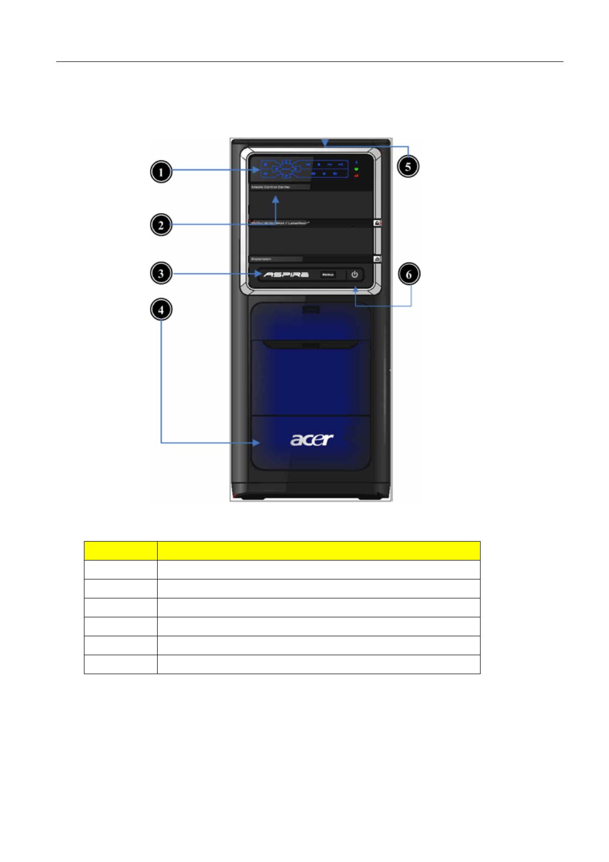
Aspire ASM7720 Front Panel………………………………………..…….………..7
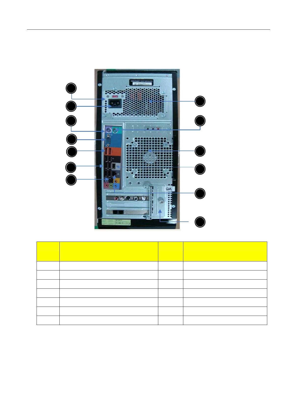
Aspire ASM7720 Rear Panel…………………..…………………………….……………………8
Hardware Specifications and Configurations………………….…….……..9
Power Management Function (ACPI support function)…………………………..…...16
Chapter 2 System Utilities 17
Entering Setup…………………………………………………………………………..18
Product Information………………………………………………………..20
Standard CMOS Features……………………………….……………………………………21
Advanced BIOS Features………………………………………..……………………23
Integrated Peripherals…………………………...…………………………………………..25
Power Management…………………………………………………………27
PC Health Status……………………………………………………………...28
Frequency/Voltage Control……………..………………………….…….29
BIOS Security Features……………………………………………………………...30
Load Default Settings………………………………………………..……. 31
Save & Exit Setup………………………………………………….…………32
Exit Without Saving………………………………………………….……..33
Chapter 3 Machine Disassembly and Replacement 34
General Information………………………………………………………. 34
Disassembly Procedure……………………………………………………36
Aspire ASM7720 Disassembly Procedure…………….…..……37
Chapter 4 Troubleshooting 51
Chapter 5 Jumper and Connector Information 52
Jumper Setting…………………………………………………..………………..52
Chapter 6 FRU (Field Replaceable Unit) List 57
Exploded Diagram………………………………………………………….58
1
System Specifications
Features
Operating System
Microsoft Windows Vista Premium 64-bit
Processor
Socket Type: Intel® Socket T LGA 1366 pin
Processor Type:
Intel Bloomfield i7 CPUs
FSB 1600 MHz CPUs
Chipset
Intel X58 + ICH10R
PCB
Form Factor: Micro ATX
Dimension/Layer: 244mm x244mm
Memory
Memory Type: DDR3 1066
Support single channel 64 bit mode with maximum memory size up to 12GB
Support un-buffered DIMM (ICH10R)
DIMM Slot: 6
Memory Max: 1GB to 12GB DDR3 memory technologies
Capacity: Up to 2GB per DIMM with maximum memory size up to 12GB
PCI
PCI Express Slot Type: x16
PCI Express x16 Slot Quantity: 2
PCI Express Slot Type: x4
PCI Express x4 Slot Quantity: 1
PCI Express Slot Type: x1
Chapter 1Chapter 1
2
PCI Express x1 Slot Quantity: 1
SATA
Slot Type: SATA slot
Slot Quantity: 6
Storage Type support:
HDD/CD-ROM/CD-RW/DVD-ROM/DVD-RW/DVD+RW/DVD Dual/DVD
SuperMultiPlus/Blu-Ray ODD
Audio
Audio Type: HD audio codec
Audio Channel: 7.1 channel
Audio Controller /Codec: ALC888S-VE 7.1
Connectors support:
Rear 6 jack follow HD audio definition,
Audio jacks color coding: should meet Microsoft Windows Logo Program
Device Requirements: Audio-0002
1 front panel audio header (2*5)
S/N ratio: 90 dB at rear output jack
LAN
MAC Controller: ICH10R
Should be worked under 10M/100M/1000Mbs environment
PHY: Intel 82567LF Boazman Gbe Ethernet LAN PHY.
USB
Controller Type: ICH10R
Ports Quantity: 12
6 back panel ports
On-board: 3 2*5 headers ( 6 ports)
4 ports for front daughter board
2 ports for internal card reader
3
Connector Pin: standard Intel FPIO pin definition
Data transfer rate support:
USB 2.0/1.1
Design Criteria:
Should meet Acer USB drop criteria
1394
Controller: VIA 6315N 1394a controller
Connector Quantity: 2
1 rear 6pin IEEE1394 port
1 2x5pin onboard jumper
BIOS
BIOS Type: Phoenix Award or AMI Kernel with Acer skin
Size: 32Mb
Note:
Boot ROM should be included (PXE function should be built in with default
and RPL function is optional by service BIOS)
BIOS shall auto detect FDD to avoid checksum error when boot
I/O Connector
Controller: Super I/O ITE8720 (F stepping or after; must full support Intel
platform)
Rear I/O Connector
1 PS/2 Keyboard port,
1 PS/2 Mouse port,
2 e SATA ports
1 RJ45 LAN port,
1 IEEE 1394 port
6 USB ports
7.1 channel phone jack (6 audio jacks)
4
On-board connectors
1 CPU socket
6 DDR-3 memory sockets
2 PCI Express x16 slot
1 PCI Express x 4 slots
1 PCI Express x 1 slots
6 SATA connectors(Need to confirm no interfere with gfx card)
3 2*5 pin Intel FPIO specification USB pin connectors (follow Intel FPIO standard
Specification)
1 2*5 pin IEEE1394 jumper
1 2*5 pin Intel FPIO spec. Microphone In/ Headphone Out pin connectors
1 serial port 2*5 pin connector
1 4 pin CPU/SYS Fan connector
5 3 pin System FAN connector with linear circuit
1 24pin + 8pin ATX interface PS3/PS2 SPS connector
1 2*7 pin front panel IO header
1 Jumper for clear CMOS
1 on board buzzer
Color management for on board connecter (pls provide proposal)
Power Supply
Power Supply Mounting Features
Chassis accepts ATX-style power supply
Chasses accepts PS2, PS3 style power supply
Features for internal mounting tab
Location of 4 external mounting holes
Power Supply Electrical Design Feature
400W ~1000W in stable mode (Acer Assign System Power Unit)
Voltage design should be covered +5V, +3.3V, +12V, +5VSB, -12V (attention to
5
12V output capability)
Demand for both PFC/Non-PFC solutions (two different quotations are
needed)
Minimum 6 Serial ATA power connector solution should be included (by
default)
Minimum 3 6-pin graphic card connector included
Minimum 2 big 4-pin power connector included
Full Range PSU
PS2 style
6
Block Diagram
7
Aspire ASM7720 Front Panel
The computer’s front panel consists of the following:
Label Description
1 Media Control Center
2 Optical drive
3 Speaker /Microphone jack
4 Gateway Logo
5 Card reader
6 Power button
8
Aspire M5700 Rear Panel
1
10
3
2
4
7
9
8
12
13
5
4
6
11
Label
Description
Label Description
1 Voltage selector switch 8 Fan aperture
2 Power card socket 9 PS/2 mouse connecter
3 PS/2 keyboard connecter 10 System FAN
4 Serial port 11 1394 connector
5 ESATA port 12 LAN connector
6 USB 2.0 connector 13 Lock Handle
7 Audio connector
9
Hardware Specifications and Configurations
Processor
Item
Specification
Type Intel Bloomfield i7 CPUs
Socket LGA 1366 pin
FSB 1600 MHz
Minimum operating
speed
0 MHz (If Stop CPU Clock in Sleep State in BIOS
Setup is set to Enabled.)
BIOS
Item
Specification
BIOS code programmer Phoenix Award or AMI Kernel with Acer
skin
BIOS version R01-A1
BIOS ROM type SPI Flash
BIOS ROM size 32Mb
Support protocol SMBIOS(DMI)2.4/DMI2.0
Device Boot Support
- 1st priority: SATA HDD
- 2nd priority: CD-ROM
- 3rd priority: FDD
- 4th priority: LAN
- 5th priority: USB device
Support to LS-120 drive YES
Support to BIOS boot block
feature
YES
10
BIOS Hotkey List
Hotkey Function Description
Del Enter BIOS Setup Utility Press while the system is booting to
enter BIOS Setup Utility.
Main Board Major Chips
Item
Specification
North Bridge Intel X58
South Bridge ICH 10R
APG controller Intel X58
Super I/O controller ITE 8720
Audio controller Realtek HD audio codec ALC888S-VE codec 7.1
(co-lay with ALC888)
LAN controller Intel 82567LF Boazman Gbe Ethernet LAN PHY
HDD controller ICH 10R
Keyboard controller ITE 8720
11
Memory Combinations
Slot
Memory Total Memory
Slot 1 1GB, 2GB 1GB ~2GB
Slot 2 1GB, 2GB 1GB ~2GB
Slot 3 1GB, 2GB 1GB ~2GB
Slot 4 1GB, 2GB 1GB ~2GB
Slot 5 1GB, 2GB 1GB ~2GB
Slot 6 1GB, 2GB 1GB ~2GB
Maximum System Memory Supported 1GB ~12GB
System Memory
Item
Specification
Memory slot number 6 slot
Support Memory size per socket 1GB/2GB
Support memory type DDR3
Support memory interface DDR3 1066MHz
Support memory voltage 1.5V
Support memory module package 240-pin DDR3
Support to parity check feature Yes
Support to error correction code
(ECC) feature
No
Memory module combinations
Y
ou can install memor
y
modules in an
y
combination as long as they match the
above specifications.
12
Audio Interface
Item
Specification
Audio controller Intel ICH 10R
Audio controller type ALC888S-VE
Audio channel codec 7.1
Audio function control Enable/disable by BIOS Setup
Mono or stereo Stereo
Compatibility Sound Blaster Pro/16 compatible
Mixed digital and analog high
performance chip Enhanced stereo
full duplex operation High
performance audio accelerator and
AC’97 support Full native DOS
games compatibility Virtual FM
enhances audio experience through
real-time FM-to-Wavetable
conversionMPU-401 (UART mode)
interface for Wavetable s
y
nthesizers
and MIDI devices Integrated dual
game port Meets AC’97and WHQL
specifications
Music synthesizer Yes, internal FM synthesizer
Sampling rate 48 KHz (max.)
MPU-401 UART support Yes
Microphone jack Supported
Headphone jack Supported
13
SATA Interface
Item
Specification
SATA controller Intel ICH 10R
SATA controller resident bus PCI bus
Number of SATA channel SATA X 6
Support bootable CD-ROM YES
USB Port
Item
Specification
Universal HCI USB 2.0/1.1
USB Class Support legacy keyboard for legacy
mode
USB Connectors Quantity 6 back panel ports
4 ports for front daughter board
2 ports for 3.5’’ card reader module
14
Environmental Requirements
Item
Specification
Temperature
Operating +5°C ~ +35°C
Non-operating -20 ~ +60°C (Storage package)
Humidity
Operating 15% to 80% RH
Non-operating 10% to 90% RH
Vibration
Operating (unpacked) 5 ~ 500 Hz: 2.20g RMS random, 10 minutes per axis
in all 3 axes
5 ~500 Hz: 1.09g RMS random, 1 hour per axis in all 3
axes
  • Page 1 1
  • Page 2 2
  • Page 3 3
  • Page 4 4
  • Page 5 5
  • Page 6 6
  • Page 7 7
  • Page 8 8
  • Page 9 9
  • Page 10 10
  • Page 11 11
  • Page 12 12
  • Page 13 13
  • Page 14 14
  • Page 15 15
  • Page 16 16
  • Page 17 17
  • Page 18 18
  • Page 19 19
  • Page 20 20
  • Page 21 21
  • Page 22 22
  • Page 23 23
  • Page 24 24
  • Page 25 25
  • Page 26 26
  • Page 27 27
  • Page 28 28
  • Page 29 29
  • Page 30 30
  • Page 31 31
  • Page 32 32
  • Page 33 33
  • Page 34 34
  • Page 35 35
  • Page 36 36
  • Page 37 37
  • Page 38 38
  • Page 39 39
  • Page 40 40
  • Page 41 41
  • Page 42 42
  • Page 43 43
  • Page 44 44
  • Page 45 45
  • Page 46 46
  • Page 47 47
  • Page 48 48
  • Page 49 49
  • Page 50 50
  • Page 51 51
  • Page 52 52
  • Page 53 53
  • Page 54 54
  • Page 55 55
  • Page 56 56
  • Page 57 57
  • Page 58 58
  • Page 59 59
  • Page 60 60
  • Page 61 61
  • Page 62 62
  • Page 63 63
  • Page 64 64

Acer Aspire ASM7720 User manual

Category
Motherboards
Type
User manual
This manual is also suitable for

Ask a question and I''ll find the answer in the document

Finding information in a document is now easier with AI