Mobility Electronics PCI Expansion System P13RR-TEL User manual
- Category
- Networking
- Type
- User manual
This manual is also suitable for

PCI Expansion System
User's Manual
13 Slot PCI to PCI Expansion
With Surveillance Pro 2 Remote Monitoring
and SNMP Capability
Model: P13RR-TEL

Copyright © 2006 Mobility Electronics, Inc.
This publication is protected by Federal Copyright Law, with all rights
reserved. No part of this publication may be copied, photocopied,
reproduced, stored in a retrieval system, translated, transmitted or
transcribed, in any form or by any means manual, electric, electronic,
electro-magnetic, mechanical, optical or otherwise, in whole or in part
without prior written consent from Mobility Electronics, Inc.
Limitation of Liability
Information presented by Mobility in this manual is believed to be
accurate and reliable. However, Mobility assumes no responsibility for
its use. No license is granted by implication or otherwise to any rights of
Mobility.
Product specifications and prices are subject to change without notice.
Trademark References
Trademarks and registered trademarks are proprietary to their
respective manufacturers.

MAGMA
Table of Contents i
Table of Contents
PREFACE...............................................................................................I
Advisories ............................................................................................... i
Safety Instructions...................................................................................ii
When Working Inside a Computer ..........................................................ii
Protecting Against Electrostatic Discharge ............................................iii
CHAPTER 1 INTRODUCTION ..........................................................1
General Specifications ...........................................................................1
Pre-Installation Information ....................................................................1
Parts List................................................................................................2
Tools Required for Installation................................................................ 2
CHAPTER 2 HARDWARE INSTALLATION .....................................3
Before you Begin.................................................................................... 4
Install PCI Host Interface Card...............................................................4
Attach PCI Expansion and Power Cable................................................5
Recheck the Installation.........................................................................6
Applying Power Correctly.......................................................................6
Starting Up:................................................................................................... 6
Shutting Down:.............................................................................................. 7
CHAPTER 3 VERIFY INSTALLATION.............................................. 8
Windows 2000 and XP...........................................................................8
Mac OS X...............................................................................................9
CHAPTER 4 INSTALL 3
RD
PARTY PCI CARDS............................. 11
Remove PCI Expansion Chassis Cover...............................................11
PCI Expansion Interface Card.............................................................. 12
Install PCI Cards in PCI Expansion Chassis........................................ 13
System Should Be Up and Running.....................................................14
Finishing Touches................................................................................15
Rack Installations........................................................................................ 16
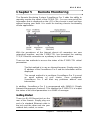
CHAPTER 5 REMOTE MONITORING........................................... 17
Getting Started..................................................................................... 17
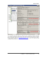
Surveillance Pro 2 Web Page ..............................................................18
Configuring Surveillance Pro 2............................................................. 18
Chassis Name............................................................................................. 19
IP Address .................................................................................................. 19
Subnet Mask and Gateway Address .......................................................... 21
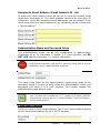
Surveillance Pro 2 Email Notification Setup ............................................... 22
SMTP Address.................................................................................... 22
Recipient’s Email Address (Email Address #1 - #4)........................... 23

MAGMA
ii Table of Contents
Administration Name and Password Setup ................................................23
From Email Address.................................................................................... 23
Finalizing Surveillance Pro 2 Configuration ................................................ 24
Removing Faults From Surveillance Pro 2 ................................................. 24
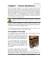
CHAPTER 6 CHASSIS MAINTENANCE.........................................25
“Hot-Swappable” Power Supply ...........................................................25
Replacing a Fan ...................................................................................26
Adjusting the Digital Display Window ...................................................27
CHAPTER 7 TROUBLESHOOTING................................................28
Locate the Problem ..............................................................................28
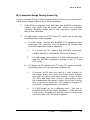
My Computer Can’t Find the PCI Expansion System.................................29
When Nothing Works.................................................................................. 30
My Computer Hangs During Power Up............................................... 31
My PCI Card Doesn’t Work......................................................................... 32
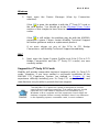
Support for 3
rd
Party PCI Cards..........................................................33
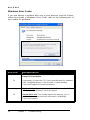
Windows Error Codes.........................................................................34
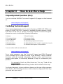
CHAPTER 8 HOW TO GET MORE HELP.......................................36
Frequently Asked Questions (FAQ)......................................................36
Contacting Technical Support ..............................................................36
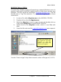
MAGMA Debug Utility.................................................................................37
PCIScope Software Utility...........................................................................38
Returning Merchandise to MAGMA......................................................40
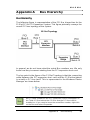
APPENDIX A BUS HIERARCHY.....................................................41
Bus Hierarchy.......................................................................................41
APPENDIX B NEED MORE SLOTS?...............................................42
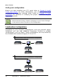
Multiple PCI Expansion System Configurations ...................................42
Fan-Out....................................................................................................... 43
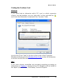
Verify your configuration..................................................................... 44
Daisy-Chaining............................................................................................ 45
Verify your configuration..................................................................... 46
Combination Configurations........................................................................ 46
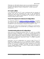
PCI Card Conflicts................................................................................47
Power-On Sequence for Advanced Configurations..............................47
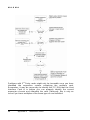
Troubleshooting Advanced Configurations...........................................47
Finding the Problem Card...................................................................49
APPENDIX C COMPLIANCE ..........................................................50
FCC......................................................................................................50
Industry Canada...................................................................................50
CE ........................................................................................................50

MAGMA
Preface i
Preface
Advisories
Four types of advisories are used throughout this manual to provide
helpful information, or to alert you to the potential for hardware damage
or personal injury. They are Notes, Cautions, Warnings, and Dangers.
The following is an example of each type of advisory.
NOTE
An amplifying or explanatory comment related to procedural steps or
text.
CAUTION
Used to indicate and prevent the following procedure or step from
causing damage to the equipment.
WARNING
Used to indicate and prevent the following step from causing injury.
DANGER or STOP
Used to indicate and prevent the following step from causing serious
injury or significant data loss.
Disclaimer: We have attempted to identify most situations that may
pose a danger, warning, or caution condition in this manual. However,
Mobility Electronics, Inc. does not claim to have covered all situations
that might require the use of a Caution, Warning, or Danger indicator.

MAGMA
ii Preface
Safety Instructions
Always use caution when servicing any electrical component. Before
handling the MAGMA PCI Expansion chassis, read the following
instructions and safety guidelines to prevent damage to the product and
to ensure your own personal safety. Refer to the “Advisories” section
for advisory conventions used in this manual, including the distinction
between Dangers, Warnings, Cautions, and Notes.
♦ Always use caution when handling/operating the computer.
Only qualified, experienced, authorized electronics personnel
should access the interior of the computer. The power supplies
produce high voltages and energy hazards, which can cause
bodily harm.
♦ Use extreme caution when installing or removing components.
Refer to the installation instructions in this manual for
precautions and procedures. If you have any questions,
please contact Mobility Technical Support.
High voltages are present inside the expansion chassis when the
unit’s power cord is plugged into an electrical outlet. Disconnect the
power cord from its source before removing the system cover.
Never modify or remove the radio frequency interference shielding from
your workstation or expansion unit. To do so may cause your installation
to produce emissions that could interfere with other electronic
equipment in the area of your system.
When Working Inside a Computer
Before taking covers off a computer, perform the following steps:
1. Turn off the computer and any peripherals
2. Disconnect the computer and peripherals from their power
sources to prevent electric shock or system board damage.
3. Disconnect any telephone or telecommunications lines from
the computer.

MAGMA
Preface iii
In addition, take note of these safety guidelines when appropriate:
♦ To help avoid possible damage to systems boards, wait five
seconds after turning off the computer before removing a
component, removing a system board, or disconnecting a
peripheral device from the computer.
♦ When you disconnect a cable, pull on its connector or on its
strain-relief loop, not on the cable itself. Some cables have a
connector with locking tabs. If you are disconnecting this type
of cable, press in on the locking tabs before disconnecting the
cable. As you pull connectors apart, keep them evenly aligned
to avoid bending any connector pins. Also, before connecting a
cable, make sure both connectors are correctly oriented and
aligned.
Do not attempt to service the system yourself except as explained in
this manual. Follow installation instructions closely.
Protecting Against Electrostatic Discharge
Electrostatic Discharge (ESD) Warning
Electrostatic Discharge (ESD) is the enemy of semiconductor
devices. You should always take precautions to eliminate any
electrostatic charge from your body and clothing before touching any
semiconductor device or card by using an electrostatic wrist strap
and/or rubber mat.
Static electricity can harm system boards. Perform service at an ESD
workstation and follow proper ESD procedure to reduce the risk of
damage to components. Mobility strongly encourages you to follow
proper ESD procedure, which can include wrist straps and smocks,
when servicing equipment.
You can also take the following steps to prevent damage from
electrostatic discharge (ESD):
♦ When unpacking a static-sensitive component from its shipping
carton, do not remove the component’s anti-static packaging
material until you are ready to install the component in a
computer. Just before unwrapping the anti-static packaging,
be sure you are at an ESD workstation or grounded.

MAGMA
iv Preface
♦ When transporting a sensitive component, first place it in an
anti-static container or packaging.
♦ Handle all sensitive components at an ESD workstation. If
possible, use anti-static floor pads and workbench pads.
♦ Handle components and boards with care. Don’t touch the
components or contacts on a board. Hold a board by its edges
or by its metal mounting bracket.

MAGMA
Chapter 1 Introduction 1
Chapter 1 Introduction
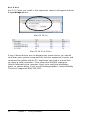
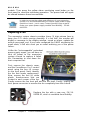
General Specifications
The MAGMA P13RR-TEL is a rugged COTS (Commercial-Off-The-
Shelf) 13 Slot PCI to PCI Expansion System designed specifically for
industrial telephony and military-grade configurations requiring remote
monitoring capability. In addition, this expansion was designed to meet
MIL-STD 461E. The expansion chassis is fully compliant with the PCI
Local Bus Specification. This MAGMA expansion system consists of a
PCI Host Interface Card, a PCI expansion cable (a shielded, high-speed
cable), a 16 gauge steel expansion chassis containing a 13 slot PCI
backplane, the Surveillance Pro 2 remote monitoring system and status
panel, a redundant power supply, and high volume cooling fans.
Item Description
Backplane: 13 standard PCI slots 32-bit / 33MHz
Enclosure: Black, 4U Rack-Mount
Dimensions: 19"W x 7"H x 18"D
Weight: 35lbs or 15.9kg
Standard Cable Length: 1 meter
PCI Local Bus Specification: Revision 2.2
PCI Bridge Architecture Spec: Revision 1.1
Interconnect Bandwidth: 132 MB/sec (Theoretical Max. of PCI 33/32)
Cooling: (3) 120mm 92CFM fans
Power Supply: Dual Redundant N+1 400W Power Supply
MTBF: 53,000 hours
Operating Environment:
0º to 50º C Operating Temperature
-20º to 60º C Storage Temperature
5% to 85% Relative Humidity, Non-condensing
Operating Systems: Windows XP/2000
Mac OS X version 10.2.2+
RedHat Linux 9
Warranty: 1 Year Return to Factory
Available Options: 1.5-meter cable (PN: SUBCBL1.5HF)
CardBus Card: required to use the expansion
chassis with a laptop computer (PN: SUBCBHIF)
Rack mount slide kit (PN: RSLIDES-XX)
Pre-Installation Information
Before using the MAGMA expansion chassis you should perform the
following steps:
• Inventory the shipping carton contents for all of the required parts
• Gather all of the necessary tools required for installation
• Read this manual.

MAGMA
2 Chapter 1 Introduction
Parts List
The following parts are provided:
Qty Item
1 13 Slot PCI to PCI Expansion Chassis
1 PCI Expansion Cable (1-meter or 1.5-meter)
1
1 PCI Host Interface Card
13 Long card retainers
13 Short card retainers
2 U.S. Standard 115V power cord
1 User’s Manual
1 Software CD-ROM
1
The MAGMA PCI expansion cable uses a 68-pin connector; however, it is NOT
an “off-the-shelf” SCSI cable. The MAGMA PCI expansion cable is a custom
cable designed specifically for PCI Expansion.
Tools Required for Installation
In order to complete the installation of the MAGMA
expansion system you will need a Phillips-head
screwdriver.

MAGMA
Chapter 2 Hardware Installation 3
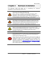
Chapter 2 Hardware Installation
The following steps will guide you in completing the hardware
installation of your MAGMA P13RR-TEL.
Electrostatic Discharge (ESD) Warning
All PCI cards are susceptible to electrostatic discharge. When
moving PCI cards, it is best to carry the cards in anti-static
packaging. If you need to set a PCI card down, be sure to place it
inside or on top of an anti-static surface. For more information, see
“Protecting Against Electrostatic Discharge” in the Preface.
High voltages are present inside the expansion chassis when the
unit’s power cord is plugged into an electrical outlet. Disconnect the
power cord from its source before removing the enclosure cover.
Turning the system power off at the power on/off switch does not
remove power to components. High voltage is still present.
Before touching anything inside the enclosure, move to an ESD
station and follow proper ESD procedure. Failure to do so may result
in electrostatic discharge damaging the computer or its components.
For more information, see “Protecting Against Electrostatic
Discharge” in the Preface.
If your MAGMA expansion chassis was not purchased directly from
Mobility Electronics, Inc., you must check to ensure that it doesn’t
contain any pre-installed PCI cards.
Check the rear side of the chassis to see if any PCI cards are
visible in the slots. If you see a PCI card, you should continue
installation using instructions provided by your dealer. If no
separate instructions are available, remove the cover by
using instructions in
Chapter 4 Install 3
rd
Party PCI Cards.
Then remove the card as normal. If no PCI card is visible,
then continue with the cable installation.

MAGMA
4 Chapter 2 Hardware Installation
Before you Begin
The 400W redundant power supply is auto-switching. These means that
it will automatically switch to match whatever source power you are
using. Since all products ship with a US Standard 115V power cord, you
will need to use a power cord adapter for non-US Standard 115V power
sources.
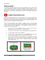
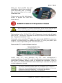
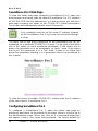
Install PCI Host Interface Card
Begin the installation of your PCI expansion host card by first powering
down the host computer. Use the procedures for shutting down your
operating system and shutting off power to your system provided in your
owner’s manual or system documentation.
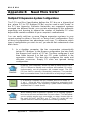
The PCI Host Interface Card includes a voltage switch in the top right
corner of the board that may need to be adjusted for proper installation.
It is an easy process to determine if the voltage switch needs to be
adjusted for your configuration.
1. Insert the PCI Host Interface Card into a vacant PCI slot by
gently pushing the card until it is firmly seated.
2. Secure the card in the PCI slot opening with a mounting screw.
3. Turn on power to the host computer.
4. If both LEDs shown below are lit, DO NOT adjust the dip
switch, simply power down and continue to step two.
5. If only the +5V LED is lit, shut down your computer, then flip
the switch to the ON position before continuing to the next
step. When you power up the computer again, both LEDs
should now be lit.

MAGMA
Chapter 2 Hardware Installation 5
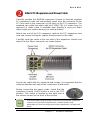
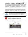
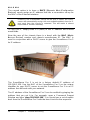
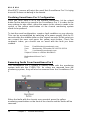
Attach PCI Expansion and Power Cable
Carefully position the MAGMA expansion chassis so that the supplied
PCI expansion cable will conveniently reach from the connector of the
PCI host card to the connector on the back of the PCI expansion. The
standard size cable that ships with the P13RR-TEL is 1 meter long. An
optional 1.5 meter cable is available from Mobility in case you didn’t
order it with your system during your initial purchase.
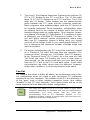
Attach one end of the PCI expansion cable to the PCI expansion host
card and secure it using the captive thumbscrews on the cable.
Carefully route the cable to the rear side of the expansion chassis and
attach it to the 68-pin connector, as shown below:
Secure the cable with the captive thumb-screws. It is important that the
cable be attached securely to the connectors at both ends.
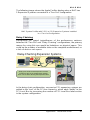
Before connecting the power cords, check that the
expansion chassis On/Off switch is set to the OFF
position. This switch is located on the right side of
the monitor control on the front of the chassis.
If at all possible, plug all power cords from the MAGMA expansion
chassis and your host computer into a shared power strip,
preferably one that has surge and noise suppression circuitry built
into it.

MAGMA
6 Chapter 2 Hardware Installation
Recheck the Installation
Check your installation before powering up the MAGMA expansion
chassis for the first time. Although the power supply has an over voltage
protection device built into it, it may not "trip" in time to fully protect a
device that has been improperly connected, or whose power cable has
been damaged.
Applying Power Correctly
Starting Up:
You must apply power to the MAGMA expansion chassis BEFORE you
power up your computer. This will allow the higher numbered PCI buses
in the PCI bus hierarchy to be at a stable state when the host system
issues its master power-on bus reset. In systems that perform automatic
PCI bus configuration, this will allow the configuration code to recognize
the PCI bus hierarchy and any attached
devices.
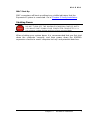
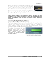
There is an On/Off switch on the front panel, as
well as LED indicators to indicate power status.
Verify that the green power indicators are ON.
Windows XP and Windows 2000 Start Up
As your Windows XP/2000 computer starts
up, you will see a small message box pop-
up in the lower-right corner of the screen to
alert you that Windows has found new
hardware.
You are now ready to go. No drivers are needed. Now go to
Chapter 3
Verify Installation.

MAGMA
Chapter 2 Hardware Installation 7
MAC Start Up
MAC computers will boot up without any visible indicators that the
Expansion System is connected. Go to
Chapter 3 Verify Installation.
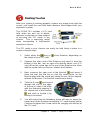
Shutting Down:
DO NOT TURN OFF THE MAGMA EXPANSION CHASSIS UNTIL
YOU HAVE SHUT DOWN YOUR COMPUTER COMPLETELY! It
can cause a system lockup and loss of any unsaved data.
When shutting your system down, it is recommended that you first shut
down the computer correctly, and then power down the MAGMA
expansion chassis to avoid ‘computer lock-up’ and potential data loss.

MAGMA
8 Chapter 3 Verify Installation
CHAPTER 3 Verify Installation
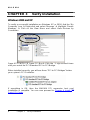
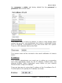
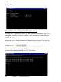
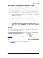
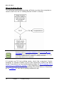
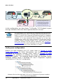
Windows 2000 and XP
To verify a successful installation on Windows XP or 2000, find the ‘My
Computer’ icon Æ Right-click and select ‘Manage’ Æ Highlight ‘Device
Manager’ Æ Click on the View Menu and select View Devices by
Connection
Open ACPI (BIOS) Æ Open PCI BusÆ Click the ‘+’ sign several times
until your reach the PCI Standard PCI to PCI Bridge.
When installed correctly, you will see three “PCI to PCI Bridges” below
your system’s PCI Controller.
If everything is OK, then the MAGMA PCI expansion host card
installation is complete. You can now proceed to
Chapter 4 Install 3
rd
Party PCI Cards
.

MAGMA
Chapter 3 Verify Installation 9
If, however, the installation was unsuccessful, you may not see the PCI
to PCI Bridge, or it will have a small yellow
in front of it.
Proceed to
Chapter 7 Troubleshooting for help with Windows installation
problems.
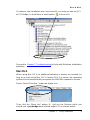
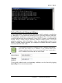
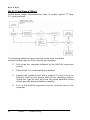
Mac OS X
When using Mac OS X no additional software or drivers are needed. As
long as you are using Mac OS X Version 10.2.2 or newer, the operating
system should automatically recognize the MAGMA expansion chassis.
Select “About This Mac” under the Apple Icon
Then click the “More Info” button Æ click on the Devices tabÆ you
should see a pci-bridge device listed under PCI as shown below:

MAGMA
10 Chapter 3 Verify Installation
Any PCI Cards you install in the expansion chassis will appear behind
the pci-bridge device.
Mac OS 10.2.x
Mac OS 10.3.x & 10.4.x
If any of these devices are not displayed as shown above, you should
shut down your system (computer first, then the expansion chassis) and
reconnect the cables and the PCI expansion host card to ensure that
you have a solid connection. Then restart the MAGMA expansion
chassis followed by the computer. Next, try to verify the installation
again, as shown above. If you are still having problems, contact Mobility
Technical Support at (858) 530-2511.

MAGMA
Chapter 4 Install 3
rd
Party PCI Cards 11
Chapter 4 Install 3
rd
Party PCI Cards
This chapter provides information on how to install 3
rd
Party PCI cards
into your MAGMA expansion chassis. More details on the installation of
individual cards are provided by the card’s manufacturer. This chapter is
provided as a simple guide to help you install your PCI cards in the
chassis.
For the purpose of installation, the MAGMA expansion chassis functions
exactly as a standard desktop computer chassis. Always follow the
manufacturer’s instructions for installing their card on a desktop
computer.
We will provide reasonable technical support with 3
rd
Party PCI
cards. However, if you have verified a successful installation of the
MAGMA expansion system (as defined in Chapter 3), but
experience difficulty installing your 3
rd
Party PCI cards, the PCI
card manufacturer should be able to provide the best support.
Remove PCI Expansion Chassis Cover
Two captive thumb screws retain the cover on the expansion chassis.
Loosen them to release the cover.

MAGMA
12 Chapter 4 Install 3
rd
Party PCI Cards
Slide the enclosure cover
backwards, disengaging it from
the guides at the front of the
enclosure, by firmly grasping the
cover lip and pulling the cover
backward about ¼” and then lifting
the cover off.
When replacing the enclosure cover, be sure that the front edge
guides on the cover engage the inner lip of the enclosure.
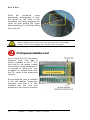
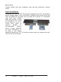
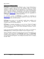
PCI Expansion Interface Card
Next, check the PCI Expansion
Interface Card. This card is
factory installed in the 1
st
PCI
slot next to the power supply
connections on the backplane. It
is required to allow your host
computer to communicate with
the PCI cards in the expansion
chassis.
Ensure that the card is installed
in the slot labeled “Expansion
Interface” and that it is fully
inserted into the slot and
fastened to the chassis correctly.
Page is loading ...
Page is loading ...
Page is loading ...
Page is loading ...
Page is loading ...
Page is loading ...
Page is loading ...
Page is loading ...
Page is loading ...
Page is loading ...
Page is loading ...
Page is loading ...
Page is loading ...
Page is loading ...
Page is loading ...
Page is loading ...
Page is loading ...
Page is loading ...
Page is loading ...
Page is loading ...
Page is loading ...
Page is loading ...
Page is loading ...
Page is loading ...
Page is loading ...
Page is loading ...
Page is loading ...
Page is loading ...
Page is loading ...
Page is loading ...
Page is loading ...
Page is loading ...
Page is loading ...
Page is loading ...
Page is loading ...
Page is loading ...
Page is loading ...
Page is loading ...
Page is loading ...
Page is loading ...
-
 1
1
-
 2
2
-
 3
3
-
 4
4
-
 5
5
-
 6
6
-
 7
7
-
 8
8
-
 9
9
-
 10
10
-
 11
11
-
 12
12
-
 13
13
-
 14
14
-
 15
15
-
 16
16
-
 17
17
-
 18
18
-
 19
19
-
 20
20
-
 21
21
-
 22
22
-
 23
23
-
 24
24
-
 25
25
-
 26
26
-
 27
27
-
 28
28
-
 29
29
-
 30
30
-
 31
31
-
 32
32
-
 33
33
-
 34
34
-
 35
35
-
 36
36
-
 37
37
-
 38
38
-
 39
39
-
 40
40
-
 41
41
-
 42
42
-
 43
43
-
 44
44
-
 45
45
-
 46
46
-
 47
47
-
 48
48
-
 49
49
-
 50
50
-
 51
51
-
 52
52
-
 53
53
-
 54
54
-
 55
55
-
 56
56
-
 57
57
-
 58
58
-
 59
59
-
 60
60


Mobility Electronics PCI Expansion System P13RR-TEL User manual
- Category
- Networking
- Type
- User manual
- This manual is also suitable for
Ask a question and I''ll find the answer in the document
Finding information in a document is now easier with AI