Page is loading ...

Owner's Manual
10 in. Stationary
TABLE SAW
Model No.
315.228310
Save this manual for
future reference
_, CAUTION: Read and follow all
Safety Rules and Operating
Instructions before first use of this
product.
".I
Customer Help Line: 1-800-932-3188
Sears, Roebuck and Co., Hoffman Estates, IL 60179 USA
Visit the Craftsman web page: www.sears.com/craftsman
972000-524
10-98
• Safety
• Features
• Assembly
• Operation
• Maintenance
• Parts List
NRTL/C

FULLONEYEARWARRANTYONCRAFTSMANTABLESAW
IfthisrRRFTSMRN Table Saw failsdue to a defect in material or workmanshipwithinone year fromthe date of
purchase.Sears willrepair it, free ofcharge,
Contacta Sears Service Center for repair.
If this productis used forcommercialor rentalpurposes,this warrantyappliesonlyfor 90 days fromthe date of
purchase.
This warrantygives you specificlegal dghts,and you may also have other rightswhichvary from state to state.
Sears, Roebuck and Co., Dept. 81"IWA, Hoffman Estates, IL 60179
Yoursaw has manyfeatures for makingcuttingoperationsmore pleasant and enjoyable. Safety,performance
and dependabilityhave been giventop priorityinthe design of thissaw makingiteasy to maintainand operate.
_, CAUTION: Carefully read throughthis entireowner's manual beforeusingyournew saw. Pay close
attentiontothe Rules ForSafe Operation and all Safety AlertSymbols,includingDanger,Wam ng and
Caution. If you useyour saw properlyand onlyfor what it isintended,you willenjoyyears of safe, reliable
service.
._ Lookfor thissymboltopoint outimportantsafety precautions.It means attention!!!Yoursafetyis involved.
WARNING:
The operationof any powertoolcan resultin foreign objects beingthrownintoyoureyes,
whichcan resultin severe eye damage. Beforebeginningpowertooloperation,always
wear safety gogglesor safety glasses with side shieldsand a full face shieldwhen needed.
We recommenda Wide Vision Safety Mask for useover eyeglasses or standardsafety
glasses withside shields,available at Sears Retail Stores.
• Warranty and Introduction.............................................................................................................................. 2
• Table Of Contents ....................................................................................................................................... 2-3
• Rules For Safe Operation ........................................................................................................................... 4-6
• Electrical......................................................................................................................................................... 7
• Glossaryand ProductSpecifications............................................................................................................. 8
• Unpackingand Accessories........................................................................................................................... 9
• Loose Parts List...................................................................................................... ...................................... 10
• Small Parts List ....................................................................................................................................... 11-12
• Tools Needed ............................................................................................................................................... 13
• Labels...................................................................................................................................................... 14-15
• Features .................................................................................................................................................. 16-17
• Assembly................................................................................................................................................. 18-27
InstallingHandwheels on Table Saw Base.................................................................................................. 18
AssemblingLeg Stand ............................................................................................................................ 18-19
CRAFTSMAN"TABLESAW315.228310 2

MountingtheLegStandontheTableSawBase........................................................................................ 19
AssemblingTable Extensions...................................................................................................................... 20
AligningTable Extensions............................................................................................................................ 20
Installingthe Rear Rail................................................................................................................................. 21
Installingthe Front Rail ................................................................................................................................ 22
AligningRip Fence and Front Rail ............................................................................................................... 23
Mountingthe Motor ...................................................................................................................................... 23
Installingthe Belt and Belt Guard ................................................................................................................ 24
Checkingthe Throat Plate............................................................................................................................ 24
Installingthe Blade Guard............................................................................................................................ 25
Aligningthe RivingKnifewith the Blade ...................................................................................................... 26
Checking Rip Fence and BladeAlignment .................................................................................................. 27
• Adjustments............................................................................................................................................. 28-32
Replacingthe Blade ..................................................................................................................................... 28
Heeling(Paralleling) the Sawblade to MiterGage Groove........................................ t............................ 29-30
Settingthe Bevel Stops and Indicator..................................................................................................... 30-31
Adjustingthe Miter Gage .............................................................................................................................. 31
Removing/ Replacing the Throat Plate ....................................................................................................... 32
• BasicOperation/bfthe Table Saw .......................................................................................................... 33-40
Causes of Kickback...................................................................................................................................... 33
AvoidingKickback........................................................................................................................................ 33
Making CuttingAids ..................................................................................................................................... 33
Types of Cuts ............................................................................................................................................... 34
Making a Cross Cut ...................................................................................................................................... 35
Making a Rip Cut .......................................................................................................................................... 35
Making a Miter Cut ....................................................................................................................................... 36
Making a Bevel CrossCut ............................................................................................................................ 36
Making a Bevel Rip Cut................................................................................................................................ 37
• Making a Compound(Bevel) Miter Cut ........................................................................................................ 38
Making a Large Panel Cut ............................................................................................................................ 39
Making a Non-Through Cut .......................................................................................................................... 39
Making a Dado Cut................................................. _..................................................................................... 40
• Maintenance................................................................................................................................................. 41
• Lubrication.................................................................................................................................................... 41
• Troubleshooting....................................................................................................................................... 42-44
• ExplodedView and Repair Parts List...................................................................................................... 46-63
• PartsOrdering / Service ................................................................................................................... backpage
3 CRRFTSMIIN"TABLESAW315.228310

The purpose ofsafety symbolsisto attractyourattentionto possibledangers.The safety symbols,and the
explanationswiththem, deserve yourcarefulattentionand understanding.The safetywarningsdo not by
themselves eliminateany danger. The instructionsor warningsthey give are not substitutesfor properaccident
preventionmeasures.
SYMBOL MEANING
A
A
A
Note:
SAFETY ALERT SYMBOL
Indicatesdanger, warning,or caution,May be used inconjunctionwithothersymbolsor
pictographs.
DANGER: Failureto obey a safety warningwill resultin seriousinjurytoyourselforto others.
Alwaysfollow the safety precautionsto reducethe riskoffire, electdcshockand personalinjury.
WARNING: Failureto obeya safety warningcan resultinsedousinjurytoyourselfor to others.
Always follow the safety precautionsto reducethe riskoffire, electdcshockand personalinjury.
CAUTION: Failureto obey a safetywarningmay resultin propertydamage or personalinjuryto
yourselfor to others.Alwaysfollowthe safety precautionsto reducetheriskoffire, electricshock
and personalinjury.
Advisesyou of informationor instructionsvital tothe operationor mainienance ofthe equipment.
IMPORTANT
Servicingrequiresextreme care and knowledgeofthe
systemand shouldbe performedonlybya qualified
servicetechnician.For servicewe suggestyou return
the toolto yournearest Sears store or repaircenter.
Always useoriginalfactory replacementpartswhen
servicing.
_1= WARNING: Do notattemptto operatethistool
untilyou have read thoroughlyand understand
completelyall instructions,safety rules, etc.
containedin this manual. Failuretocomplycan
resultin accidentsinvolvingfire, electricalshock,
or seriouspersonalinjury.Save the owner's
manual and reviewfrequently for continuingsafe
operation,and instructingotherswho may use
this tool.
READ ALL INSTRUCTIONS
KNOW YOUR POWER TOOL. Read the owner's
manual carefully.Learnthe saw's applications
and limitationsas well as the specificpotential
hazards relatedto thistool.
DO NOT USE IN DANGEROUS ENVIRON-
MENT. Do not use powertoolsnear gasolineor
otherflammable liquids,in damp or wet loca-
tions,or expose them to rain. Keep the work
area well lit.
• MAKE WORKSHOP CHILD-PROOF with
padlocksand masterswitches or by removing
starter keys.
• KEEP CHILDREN AND VISITORS AWAY. All
visitorsshouldwear safety glasses and be kepta
safe distancefrom work area. Do not let visitors
contacttoolor extensioncordwhileoperating,
• KEEP THE WORK AREA CLEAN. Cluttered
work areas and work benches inviteaccidents,
DO NOT leave toolsor pieces of woodon the
saw while itis in operation,
MAINTAIN TOOLS WITH CARE. Keep tools
sharp and clean for betterand safer perfor-
mance. Followinstructionsforlubricatingand
changingaccessories.
USE THE RIGHT TOOL FOR THE JOB. Do not
force the toolor attachmentto do a job itwas not
designedfor. Use itonlythe way it was intended.
DRESS PROPERLY. Do notwear looseclothing,
gloves, neckties,rings,bracelets,or other
jewelry. They can getcaughtand draw you into
moving parts.Rubberglovesand nonslipfoot-
wear are recommended.Alsowear protective
hair coveringto containlonghair.
ALWAYS WEAR SAFETY GLASSES WITH
SIDE SHIELDS. Everydayeyeglasses have only
impact-resistantlenses;theyare NOT safety
glasses,
NEVER STAND ON TOOL. Seriousinjurycould
occurif thetoolis tippedor ifthe blade is unin-
tentionallycontacted.
CRRFTSMRN"TABLESAW315.228310 4

BIULES FOR SAFE OPERATION (Continued)
B DO NOT OVERREACH. Keep properfootingand
balance at all times.
m
M
M
M
SECURE WORK. Use clamps or a viseto hold
workwhen practical. It'ssaferthan usingyour
handand frees bothhandsto operatetool.
USE THE PROPER EXTENSION CORD. Make
sure yourextensioncord isin goodcondition.
Use onlya cord heavyenoughto carrythe
currentyour productwilldraw. An undersized
cordwillcause a drop in linevoltageresultingin
lossof power and overheating.A wire gage size
(A.W.G.) of at least 14 isrecommendedfor an
extensioncord25 feet or less in length.If in
doubt,use the next heaviergage. The smaller
the gage number,the heavierthe cord.
AVOID ACCIDENTAL STARTING. Be sure
switchisoft when pluggingin.
REMOVE WRENCHES AND ADJUSTING
KEYS. Get in the habitof checking- before
turningon tool- that hexI_eysand adjusting
wrenchesare removedfrom tool.
M
M
M
M
M
CHECK DAMAGED PARTS. Before usingthe
toolagain, checkany damaged parts,including
guards,for properoperationand performance.
Check alignmentofmovingpads, bindingof
movingpads, breakage of pads, saw stability,
mountingand any otherconditionsthat may
affect itsoperation.A damaged part must be
propedyrepairedor replaced bya qualified
servicetechnicianat a Sears store or repair
center to avoid riskofpersonalinjury.
USE ONLY CORRECT BLADES. Use the right
blade size, style and cutting speed for the
material and the type of cut. Blade teeth should
point down toward the front of the table.
USE RECOMMENDED ACCESSORIES, Using
improperaccessoriesmay riskinjury.
USE ONLY SEARS REPLACEMENT PARTS,
Allrepairs,whether electdcalor mechanical,
shouldbe made bya qualifiedservice technician
at a Sears storeor repaircenter.
KEEP GUARDS IN PLACE and in good working
order.This includesthe blade guard, rivingknife,
and anti-kickbackpawls.
CHECK DIRECTION OF FEED. Feed work into
a blade or cutteragainst the directionof rotation
ofthe bladeor cutter only,
DISCONNECT ALL TOOLS. When notin use,
before servicing,or when changingattachments,
blades, bits,cutters,etc., all toolsshouldbe
disconnectedfrom powersupply.
M
M
DO NOT FORCE THE TOOL. It willdo tbejob
better and more safelyat the ratefor whichit
was designed.
NEVER LEAVE TOOL RUNNING UNAT-
TENDED. TURN THE POWER OFF. Do not
leave tool untilit comesto a completestop.
BEFORE MOUNTING, DISCONNECTING OR
REMOUNTING THE MOTOR; unplugthesaw
and removethe switchkey.
A
WARNING: When servicing,useonly identical
Craftsman replacementpads. Use ofany other
parts may create a hazard or cause product
damage.
M
M
M
M
M
M
M
M
M
NEVER USE THIS TOOL IN AN EXPLOSIVE
ATMOSPHERE. Normal sparkingof the motor
could ignitefumes.
MAKE SURE THE WORK AREA HAS AMPLE
LIGHTING to see the work and that no obstruc-
tionswillinterferewithsafe operation BEFORE
performingany work usingthistool.
DO NOT USE TOOL IF SWITCH DOES NOT
TURN IT ON AND OFF. Have defective switches
replaced bya qualifiedservicetechnicianat a
Sears store or repaircenter.
GUARD AGAINST ELECTRICAL SHOCK by
preventingbodycontactwith groundedsurfaces
such as pipes, radiators,ranges, refrigerator
enclosures.
GROUND ALL TOOLS. See Electricalpage.
WEAR A DUST MASK to keep from inhalingfine
particles.
PROTECT YOUR HEARING. Wear hearing
protectiondudngextended periodsof operation.
DO NOT OPERATE THIS TOOL WHILE UN-
DER THE INFLUENCE OF DRUGS, ALCOHOL,
OR ANY MEDICATION.
STAY ALERT AND EXERCISE CONTROL,
Watch whatyou are doingand use common
sense, Do not operate tool when you ere tired.
Do not rush.
AVOID AWKWARD OPERATIONS AND HAND
POSITIONS where a sudden slipcouldcause
your handto moveintothe blade. ALWAYS
make sure you have good balance,
ALWAYS SUPPORT LARGE WORK PIECES
while cuttingto minimize riskof blade pinching
and kickback.Saw may slip,walk or slidewhile
cuttinglarge or heavy boards.
5 CRAFTSMAN"TABLESAW315,228310

RULES FOR SAFE OPERATION (Continued)
• GUARD AGAINST KICKBACK. Kickbackcan
occurwhen the blade sta$$s,ddvingthe work
piece back towardthe operator. Itcan pullyour
hand intothe blade, resultingin sedouspersonal
injury.Stay out ofthe blade path and turn switch
off immediatelyifblade bindsor stalls.
USE A SUPPORT FOR THE SIDES AND BACK
OF THE SAW TABLE when sawingwide or long
workpieces. Use a sturdy"outrigger" supportif a
table extensionis morethan 24 incheslong and
is attached to the saw, to preventtipping.
CUT ONLY WOOD, PLASTIC OR WOOD-LIKE
MATERIALS. Do not cut metal.
• NEVER cutmore than one piece at a time. DO
NOT STACK more than one workpieceon the
saw table at a time.
DO NOT REMOVE THE SAW'S BLADE
GUARDS. Never operate the saw with any guard
or cover removed. Make sure all guardsare
operating propedybefol'eeach use.
NEVER PERFORM ANY OPERATION FREE-
HAND. Always place the workpieceto be cuton
the saw table and position itfirmly againstthe
fence as a backstop.
USE THE RIP FENCE. Always use a fence or
straightedge guide when ripping.
BEFORE MAKING A CUT, be sure all adjust-
mentsare secure.
• BE SURE THE BLADE PATH IS FREE OF
NAILS. Inspectfor and remove all nailsfrom
lumber beforecutting.
• BE SURE THE BLADE CLEARS THE
WORKPIECE. Never startthe saw with the blade
touchingtheworkplace.
• KEEP HANDS AWAY FROM CUTTING AREA.
Do notreach underneathworkor in blade cutting
path withyourhands and fingersfor any reason.
Alwaysturnthe power off.
• USE A PUSHBLOCK OR PUSH STICK for
workpiecessosmall that yourfingersgo under
the blade guam:d.NEVER TOUCH BLADE or
other movingpartsduringuse, for any reason.
_k WARNING: Blade coastsafter beingtumed off.
ALLOW THE MOTOR TO COME UP TO FULL
SPEED beforestartinge cutto avoidblade
bindingor stalling.
ALWAYS PUSH THE WORKP|ECE; never pullit
towardthe saw.
DO NOT FEED THE MATERIAL TOO QUICKLY.
Do notfome the workpieceagainstthe blade.
ALWAYS TURN OFF SAW beforedisconnecting
it,to avoidaccidental startingwhen reconnecting
to powersupply. NEVER leave the table saw
unattendedwhileconnectedto a powersource.
BEFORE CHANGING THE SETUP, REMOVING
COVERS, GUARDS, OR BLADE; unplugthe
saw and remove the switchkey.
KEEP TOOL DRY, CLEAN, AND FREE FROM
OIL AND GREASE. Alwaysuse a clean cloth
when cleaning. Never use brake fluids,gasoline,
petroleum-basedproducts,or any solventsto
clean tool.
KEEP BLADES CLEAN, SHARP AND WITH
SUFFICIENT SET. Sharp bladesminimize
stallingand kickback.
USE ONLY OUTDOOR EXTENSION CORDS.
Use onlyextensioncordswiththe marking
=Acceptable for use with outdoorappliances;
store cordsindoorswhilenot in use."Use
extensioncordswith an electricalratingnot less
than the saw's rating.Always disconnectthe
extensioncordfrom the outletbeforedisconnect-
ingthe productfrom the extensioncord.
• INSPECT TOOL CORDS AND EXTENSION
CORDS PERIODICALLY and, ifdamaged, have
repairedbya qualifiedsewice technicianat a
Sears store or repaircenter. Stay constantly
aware ofcord locationand keep itwell away
fromthe movingblade.
• DO NOT ABUSE CORD, Never yankcord to
disconnectitfrom receptacle. Keep cord from
heat, oil,and sharpedges.
SAVE THESE INSTRUCTIONS. Referto them
frequently and use to instructother users. Ifyou
loansomeonethis tool, loanthem these instruc-
tionsalso.
SAVE THESE INSTRUCTIONS
[RAFTSMRW TABLESAW316,228310 6

EXTENSION CORDS
Use only3-wire extensioncordsthat have 3-prong
groundingplugsand 3-pole receptaclesthat accept
thetool's plug.When usinga powertool at a consid-
erable distancefromthe powersource, use an
extensioncord heavyenoughto carrythe current that
thetool willdraw.An undersizedextensioncordwill
cause a drop in linevoltage, resultingin a loss of
powerand causingthe motorto overheat. Use the
chart providedbelowto determinethe minimumwire
size requiredin an extensioncord. Only roundjack-
eted cordslistedby Underwriter'sLaboratories(UL)
shouldbe used.
Length of Extension Cord Wire Size (A.W.G.)
Up to 25 feet 14
26-100 feet 12
When workingwith thetool outdoors,use an exten-
sioncordthat isdesignedfor outsideuse. This is
indicatedbythe lettersWA on the cord's jacket.
Beforeusing an extensioncord, inspectitfor looseor
exposedwires and cut or worninsulation.
_k CAUTION: Keep the cord away from the cutting
area and positionthe cordsothat it willnot be
caughton lumber,tools,or otherobjectsdudng
cuttingoperations.
ELECTRICAL CONNECTION
YourSears CraftsmanTable Saw ispowered bya
precisionbuiltelectricmotor. Itshouldbe connected
to a power supply that Is 120 volts, 60 Hz, AC only
(normal household current). Do not operate thistool
ondirectcurrent (DC). A substantialvoltagedrop will
causea lossofpower and the motorwilloverheat. If
the saw does not operatewhen plugged intoan
outlet,doublecheckthe power supply.
SPEED AND WIRING
The no-loadspeed of yourtable saw isapproximately
3,600 rpm.This speed isnot constantand decreases
undera load or with lowervoltage. Forvoltage, the
wiringin a shopis as importantas the motor'shorse-
powerrating.A lineintendedonlyfor lightscannot
properlycarry a powertoolmotor. Wire that isheavy
enoughfor a shortdistancewillbe too lightfor a
greaterdistance. A linethatcan supportone power
tool may not be able to supporttwo or three tools.
GROUNDING INSTRUCTIONS
In the event ofa malfunctionor breakdown, grounding
providesa path ofleast resistancefor electriccurrent
to reducethe riskofelectricshock.Thistool is
equippedwith anelectriccordhaving an equipment-
groundingconductorand a groundingplug.The plug
mustbe pluggedintoa matchingoutletthat ispropedy
installedand groundedin accordancewith all local
codes and ordinances.
Do not modifythe plug provided.Ifitwillnot fit the
outlet,have the properoutletinstalledbya qualified
electrician.Improperconnectionofthe equipment-
groundingconductorcan resultin a riskof electric
shook.The conductorwith insulationhaving an outer
surfacethat isgreen withor withoutyellowstripesis
the equipment-groundingconductor. If repairor
replacementofthe electdc cordor plug isnecessary,
do not connect the equipment-groundingconductorto
a liveterminal.
Check witha qualifiedelectricianor service personnel
ifthe groundinginstructionsare notcompletely
understood,or if indoubt as to whetherthetoolis
properlygrounded.
Repair or replacea damaged or worncordimmedi-
ately.
This toolis intendedfor use on a circuitthathas an
outletlikethe one shownin Figure 1.Italso hasa
groundingpinlike the one shown.
GROUNDING
PIN
COVEROFGROUNDED
0UTLETBOX
Fig. 1
7 rRRFTSNRN"TABLESAW31S.228310

Anti-Kickback Pawls
Toothedsafety devicesbehindthe bladedesignedto
stop a workpiece from beingkicked back at the
operatorduringa rippingoperation.
Arbor
The shafton whicha bladeor cuttingtoolis mounted.
Bevel Cut
A cuttingoperationmade withthe blade at any angle
otherthan 90" to the saw table.
Compound Cut
A cutwith both a miterangle and a bevel angle.
Crosscut
A cuttingoperation made acrossthe grain or the width
ofthe workpiece.
Dsdo
A non-throughcut thatgives a square notchortrough;
requiresa specialblade.
Featherboard
A device to helpguide workpiecesduring ripcuts.
Freehand (for table saw)
Dangerous practiceofmaking s cut withoutusingdp
or miterfences. See Safety Rules.
Gum
A sticky, sap-based residuefromwood products.
Heel
Alignmentof the blade.
Kerf
The materialremovedby the blade in a through cutor
the slotproducedby the bladein a non-throughcut.
Kickback
A hazard that can occurwhen blade bindsor stalls,
throwingworkpiece backtowardoperator.
Leading End
The end of the workpiecepushed intothe cuttingtool
first.
Miter Cut
A cuttingoperationmade with the miter gage at any
angle otherthan 0".
Molding
A non-throughcutthat givesa varied shape tothe
workpiece and requirese specialblade.
Push Stick
A device usedto feed the workpiecethroughthe saw
blade duringnarrowcuttingoperations.It helpskeep
the operator'shandswell away from the blade,
Rabbet
A notch inthe edge ofa workpiece.
Resaw
A cuttingoperationto reducethe thicknessofthe
workpieceinorder to make thinnerpieces.
Resin
A sticky,sap-based substance.
RIp Cut
A cut made withthethe grainof the workpiece.
Sswblade Path
The area directlyin linewiththe blade-- over,under,
behind, orin front ofit. Also, theworkpiecearea
whichwillbe or has been cutby theblade.
Set
The distancethat the tip ofthe saw bladetoothis bent
(or set) outwardfrom the face of the blade.
Throw-Back
Saw throwingback a workpiece;similarto kickback,
Through Sawing
Any cuttingoperationwhere the blade extends
completelythroughthe workpiece.
Trailing End
The workpieceend lastcutby the blade in a dp cut.
Workp|ece
The itemon whichthe cutting operationis beingdone.
The surfacesof a workpieceare commonlyreferredto
as faces,ends, and edges.
Worktable
The surfaceon whichthe wodq_ecerestswhile
performinga cuttingoperation.
BladeArbor 5/8 in.
Blade Diameter 10 in.
Blade Tilt 0"- 45"
TableSize withouttable extensions 20 in. x 27 in.
Table Size with table extensions 44 in. x 27 in.
Rating 120 V,60 Hz - AC only
Input 13 Amperes
No LoadSpeed 3,600 RPM
CuttingCapacitywithMiter at 0"/Bevel0": 3-3/8 in.
Cutting Capacity withMiter at O'/Bevel45": 2-1/4 in.
rRRFTSNlUI" TABLESAW$1G,228310 8

Your newtable saw has been designedto give you
manyyears of high qualityperformance.To insure
thisgoal, propercare and treatment is important.
Careful treatment beginswith removingall pads from
the cartonand checkingthem againstthe listof loose
parts.The long box containsthe rails. The large box
holdsall other parts,whichare detailed inthe Loose
PartsList.
• Separate the saw and all partsfrom the packing
materialsand checkeach againstthe packing list,
especiallythe small partsthat can be hidden inthe
packingmaterial
Note: Do notdiscard the packingmaterialsuntilyou
have carefullyinspectedthe saw, identifiedall
parts,and satisfactorily operated your new saw.
_IL WARNING: Never use gasoline, naptha, or
other highlyvolatile solvents.Do not ever let
brake fluids, gasoline,petroleum-based
products,or penetratingoilscontact plasticparts.
Such chemicalscan weaken or destroyplastic.
II Remove the wax papercoveringon the table. Use
anyordinary household type grease and spot
remover. Immediatelyapplya coat of automotive
typepaste wax to the table and table exensions.
,_ WARNING: To preventaccidental startingthat
couldcause possibleseriouspersonalinjury,
assemble all partsto yoursaw before connecting
it to power supply.Saw shouldnever be
connected topower supplywhen you are
assemblingparts,makingadjustments,installing
or removingblades, or when notin use.
,_ WARNING: If any partsare missing,do not
operate thistool untilthe missingparts are
replaced. Failuretodo so could resultinpossible
seriouspersonalinjury.
The following recommendedaccessoriesare currentlyavailable
• Fence Guide System
• Guide Master
• Box Joint &Miter Guide
• Universal Jig
• Taper Jig
• 10 in. SandingDisc
• 8 in. SandingDisc
• Elite Dado
• ExcaliburDado
• 7 in. Adj. Dado 36 tip
• 7 in.Adj. Dado 24 tip
at Sears RetailStores.
• 7 in.Stack Steel Dado
• 7 in.x 9/16 in.Stack Dado
• 7 in. MoldingHead Set
• 2 Bit MoldingHead Set
• Saw Baskets
• JointerClamps
• SpecialtyThroat Plate
• Miter Gage Hold DownClamp
• Align-A-RipXRC Rip Fence
• Dust CollectionSystem
,_ WARNING: The useof attachmentsor accessoriesnot listed mightbe hazardous.
9 [RAFTSMAN" TABLESAW315.228310

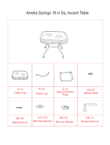
The following items are included with your Table Saw.
A
D
G
o
Q
I
J
Figure2 a
A. Table Saw Base .................................................... 1
B. Belt ....................................................................... 1
C. Belt Guard (2 Piece) ............................................. 1
D. Blade GuardAssembly
(Hardware ShownSeparately) ............................. 1
E. Wrench ................................................................. 1
F. Handwheel(Hardware Shown Separately) .......... 2
G. Leg Brace, lower(short)....................................... 2
H. Leg Brace, lower(long) ........................................ 2
I. Leg Brace, upper(short)....................................... 2
J. Leg Brace, upper (long) ........................................ 2
K. Leg........................................................................ 4
L. MiterGage ............................................................ 1
M. Motor .................................................................... 1
N. Motor MountingPlate
(Hardware Shown Separately) ............................. 1
tRRFTZMRI¢ TABLE SAW 315.228310
O. Rail, Front(Hardware ShownSeparately)............ 1
P. Rail, Rear (Hardware ShownSeparately) ............ 1
Q. RipFence ............................................................. 1
R. Blade Guard Bracket ......................... ;.................. 1
S. SwitchAssembly ......,, ......................................... 1
T. SwitchKey............................................................ 1
U. Table Extension.................................................... 2
V. Hardware for MountingMotor,MotorMounting
Plate, and BeltGuard (ShownSeparately)...........1
W. Hardware for Table Extensions
(ShownSeparately) .............................................. 1
X. Hardware for Leg Stand, LevelingFeet, and
MountingSaw Base
(ShownSeparately) .............................................. 1
Y. Hardware for Blade Guard Bracketand
Blade GuardAssembly(ShownSeparately) ........ 1
Z. Owner's Manual (Not Shown)............................... 1
10

Checkallloosepartsfromtheboxwiththelistonthepreviouspage,thefiguresbelowandonthefollowing
page,Smallitemssuchasfastenersandendcapsareshowninfigures2band2c.Followtheinstructionsin
theAssemblysectiontoassembleyournewsaw.
F. Hardware for Handwheel ................................... 2
screw (3/16-24 x 1/2 in.)..................................... 2
flat washer (3/15 in.)........................................... 2
V.
Hardware for MountingMotor,MotorMounting
Plate, and Belt Guard
Hardware for Mounting Motor ............................ 1
hex bolt (5/16-18 x 1 in.) .................................... 4
flat washer (5/16 in.) ........................................... 8
lock washer (5/16 in.) .......,.................................. 4
hex nut (5/16-18) ................................................ 4
Hardware for Motor MountingPlate ................... 1
hex bolt (5/16-18 x 5/8 in.) ................................. 2
Xo
Hardware for Leg Stand, LevelingFeet, and
MountingSaw Base
Hardware for Leg Stand ..................................... 1
carriage bolt(5/16-18 x 3/4 in.)........................ 24
flat washer (5/16 in.)......................................... 24
hex nut(5/16-18) .............................................. 24
Hardware for LevelingFeet ................................ 1
leveling foot ........................................................ 4
flatwasher (5/16 in.)........................................... 8
hex nut (5/16-18) ................................................ 8
Hardware for Belt Guard .................................... 1
hex nut (3/16-24) ................................................ 4
flat washer (3/16 in) ............................................ 4
W. Hardware for Table Extensions.......................... 1
hex bolt(5/16-18 x 1-1/4 in.).............................. 8
flatwasher (5/16 in.) ......................................... 16
hex nut (5/16-18) ................................................ 8
m
Hardware for MountingSaw Base ..................... 1
hex belt (5116-18 x 1/2 in.) ................................. 4
flat washer (5/16 in°)........................................... 8
hex nut (5116-18) ................................................ 4
Fig. 2 b
11 [IIRFrSMRIr TABLESAW31S.228310

Check all loose partsfrom the box with the listand figuresbelowand on the previouspages, Small itemssuch
as fasteners and end capsare shownin figure2 c. Followthe instructionsin the Assemblysectionto assemble
your new saw.
O. Hardware for Rail, Front..................................... 1
square head bolt (5/16-18 x 1 in..) ..................... 6
flat washer (5/16 in.) ........................................... 6
hex nut (5/16-18) ................................................ 6
end cap for front rail ........................................... 2
screw (5/32-32 x 1/2 in.) ..................................... 2
©
F,
Hardware For Rail, Rear .................................... 1
square head bolt (5/16-18 x 1 in.) ...................... 6
flat washer (5/16 in.) ........................................... 6
hex nut (5/16-18) ................................................ 6
end capfor rear rail ............................................ 2
screw (5/32-32 x 1/2 in.)..................................... 2
Y. Hardware for Blade GuardBracketand Blade
GuardAssembly
BladeGuard Bracket.......................................... 1
hex cap screw (5/16-18 x 1/2 in.)....................... 2
lock washer (5/16 in.) ......................................... 2
Blade Guard Assembly....................................... 1
socket head cap screw (1/4-20 x 3/8 in.) ........... 3
flat washer (1/4 in.) ..._......................................... 3
Fig. 2 c
CRAFTSMAN"TABLESAW315.228310 12

The followingtoolsare neededfor assemblyand alignment. Note: The fivehex keys listedbelow havebeen
providedwith yoursaw.The remainingtoolsare typicalshoptoolsand are notincludedwithyoursaw.
SMALLI MEDIUM
PHILUPSSCREWDRIVER
NUTDRIVER
8 mm,10mm,and12mrn
HEXKEYS(PROVIDED)
and6 mm
COMBINA_ONSOUARE
HAMMER
45°TRIANGLE
WRENCHES:8 mm,10mm,and12mm
FRAMINGSQUARE
ADJUSTABLEWRENCH
13 rRRFTSMRN"TABLESAW315.228310

/
The followinglabelsare found on yoursaw inthe locationsshown. Read allwarningsand thisowner'smanual
before using saw,
B
D
e
o
o
A
10 inch Table Saw
36QOIh_M120VOLTS60HzACONLY13A
WARNING:WHEN SERVICING, USE ONLY IDENTICAL
CRAFTSMANREPLACEMENTPARTS.
MODEL 315.228310 S_R.NO. _i
MAD_ IN TAJWAN
SEARS, ROEBUCK AND CO. i I
sr_l_4_ TOOL
• Customer Help Line 1-800-932-3188 ,
F
H
C
G
B
AWARNINI
• RaisedGuard
CanDropon
Spinning
Bladeand
Break.
•ToReduceThe
RiskofInjury,
GuardMust81
InPlace
DuringUse.
,Alignand
Tighten
RivingKnife
Fasteners
BeforeUse.
Fig, 4 a
CRAFTSMAN"TABLESAW315.228310 14

I _ WARNING
When Mounting an Auxiliary Fence Face, Position Mounting Hardware Beyond Arrow at Bight and Left as Indicated.
Keep Fasteners Away From Blade.
C
D E
I ] ,A,WARNING
Do Not Lift Saw With Rails Debris on rail can misalign
Lor Extensions Tables. the rip fence. Workpiece
could bind or suddenly
F
A WARNING
• Attach Blade Guard
Assembly Before
Operating this Saw
• Read Owners
kick back. You could be hit
or cut. Clean debris off
fence rail before
positioning fence.
G
,_LLONI
PUSHOFF
H
®
A WARNING
Turn Clockwise to
Increase Blade
Angle.
Turn Clockwise to Raise
Blade.
"rumCounterclockwise to
Lower Blade.
• For your safety, read owners manual before
operating saw.
• Wear eye p_otection.
• Keep blade guard down and In place for through
cuts.
• Keep hands out of path of saw blade.
• Do not perform any operation freehand.
• Know how to reduce the risk of kickback.
See instructions for ripping.
• Never reach around o¢ over/Niw blade.
• When ripping, use push stick when fence is set
2 Inches or lees from blade.
• When ripping, use push block and auxllary fence
when fence Is set between 1/2 and 2 inches from
blade. Oo nut make rip cuts narrower than 1/2 Inch.
•Tum off tool and walt for saw blade to stop before
moving workplece or changing settings.
• Disconnect the saw from the power source before
changing blade or se_icing.
• Do not expose to rbln or use in damp places.
Fig. 4 b
15 I:RRFTSMIIN"TABLESAW315.228310

KNOW YOUR TABLE SAW
ANTI-KICKBACKPAWLS
BLADE
MITER
GAGEGROOVE
TABLE
EXTENSION
BLADE
REARRAIL RIPFENCE
RIVINGKNIFE
ORSPREADER ALIGN-A-CUT TABLE
INSERT EXTENSION
SCALE
GAGE
FRONT
RAIL
BELTCOVER
BEVEL SWITCH
HANDWHEEL WITH KEY
RIPFENCE
SCALE HANDLE
HANDWHEEL
LEGSTAND
'LEVELINGFOOT
MOTOR
BEVEL
LOCKHANDLE
Fig. 5
CRAFTSMAN"TABLESAW315.228310 16

/ERVIEW
,,,e upper portionofthe blade projectsup throughthe
table, surroundedbyan insertcalled thethroat plate.
The height ofthe blade isset witha handwheel and
lockedwith a handle, bothon thefront of the cabinet.
To accommodatewide panels, the tabletop has
extensionson each side. Detailed instructionsare
providedinthe Operationsectionof this manualfor
the basiccuts:crosscuts, mitercuts, bevel cuts,and
compoundcuts.
Forcutswith the blade straightup and cuttingacross
the grain(cross cutsor mitercuts), usethe mitergage
to set the angle and pushthe wood into the blade. To
cut with the blade straight up, along the grain of the
wood (rip cuts), use the rip fence to guide the wood.
Push smallerpieces with a pushblockor pushstick.
To tiltthe blade for a bevel cut, usethe bevel
handwheelon the side ofthe cabinet. A bevel scale
on the front ofthe cabinet showsthe bladeangle.
Insidethe cabinet, adjustablepositivestopscontrol
the degree of tilt.
Use the miter gage with a bevel crosscut (compound
cut)and the ripfence with a bevel ripcut. Other cuts
requirespecialattachments,whichhave detailed
instructions to reduce risk of injury and ensurethe
best performance from your new saw.
Before attemptingto use your saw, familiarize yourself
withall operating features and safety requirements of
your Sears Craftsman table saw. The saw's features
are described below.
ALIGN-A-CUT INSERT - A pt_,sticinsert onwhich
marks may be made to indicate the locationofthe
sawcuton the workpiece.
ANTI-KICKBACK PAWLS - KickbackIs a hazard in
whichthe workpiece isthrownbacktoward the
operator. The toothed pawls are designedto snag the
workpieceto preventor reduceinjuryshouldkickback
Occur.
BEVEL HANDWHEEL - This handwheel, on the right
side ofthe cabinet, tiltsthe bladefor a bevel cut.
BEVEL SCALE - The easy-to-road scale on the front
ofthe work.standshowsthe exact blade angle.
BLADE -This saw is providedwith a Craftsman 64
tooth, 10 in. steel blade. The blade is adjustedwith
bevel and heighthandwheelson the cabinet. Bevel
anglesare lockedwith a handle belowthe front rail.
WARNING: Be sure to use onlyblades rated for
at least 5,000 rpmand recommendedfor useon
this saw. Check with yournearest Sears retail
store.
BLADE GUARD - Always keepthe guard down over
the bladefor through-sawingcuts.
BEVEL LOCK HANDLE - This handle, placedjust
under theworktable surfaceon the frontof the cabi-
net, locksthe anglesettingof theblade. Be surethe
handle ishangingstraightdownbeforetiltingthe
blade. If itis notstraightdown, itmay jam and bend
thelockingbolt.
HEIGHT HANDWHEEL - Use this handwheel to lower
and raise the blade for adjustmentsor replacement.It
is locatedon the front ofthe cabinet.
MITER GAGE - This gage alignsthe wood for a
crosscutat an angle otherthan 90". The easy-to-road
indicator showsthe exact angle for a mitercut, with
positivestopsat 90"and 45".
MITER GAGE GROOVES - The miter gage ddes in
these grooves on eitherside ofthe blade.
MITER GAGE KNOB - Locatedon themiter gage,
this knoblocksin the cuttingangleafter selection.
MOTOR (13 AMP) - The powerfulinductionmotoris
3HP, with capacitorstartand V-belt drive,and is
housedin a sturdysteel base.
RAILS - Front and rear railsprovidesupportfor large
workpiecesend the ripfence.
RiP FENCE - A sturdymetalfence guidesthe
workpieceand issecured withthe ripfence handle.
Grooves runalongthe top and sidesof the ripfence
for usa withoptionalclamps and accessories.
RIP FENCE HANDLE - The handleon the frontofthe
rip fence releasesthe ripfence or locksitin place.
RIVING KNIFE OR SPREADER - Locateddirectly.
behindthe blade, itkeeps cutedges frombindingand
supportsthe blade guard.
SCALE - Foundon the frontrail,the easy-to-road
scale providesprecise measurementsin dp cuts.
SWITCH WITH KEY - Your table saw has an easy
access power switchlocatedbelowthe frontrail.The
yellowswitchkey mustbe removedfromthe hard-
ware bag and inserted intothe switchbefore saw can
be operated. To lockthe switchinthe OFF position,
remove the switch key fromthe switch.Place the key
in a locationthatis inaccessibleto childrenand others
notqualifiedto use the tool.
TABLE EXTENSIONS - Removable stampedsteel
extensions,12 in.by 27 in., supportlarger
workpieces,
17 CRAFTSHAN"TABLESAW315.228310

Assembly isbestdone inthe area where the saw will be used. When you remove the table saw base, loose
parts, and hardware fromthe packingmatedals, check all itemswith the looseparts listand drawing. Ifyou are
unsure about thedescriptionofany part, refer tothe drawing. Ifany parts are missing,delay assemblinguntil
you have obtainedthe missingpart(s).
INSTALLING HANDWHEELS ON TABLE SAW
BASE
See Figure 6.
• Each handwheel bag containsa handwheel, a
screw (3/16-24 x 1/2 in.), and a flat washer (3/16
in.).
• Alignhandwheelstotheshaftendsthatextendfrom
thefrontand rightsideofthetable sawbase. Match
thefiatspotsonthe shaftand insidethe handwheeL
Inserta screwand a fiatwasherin thehandwheel
centerandtightenwitha 4 mmhex key.
HANDWHEEL
Note: Ifyou do not usa the leg stand and mountthe
saw table base on a bench insteadofthe legs, goto
the procedurefor Assembling TableExtensions.Be
sure the'bench surfacehas an openingfor sawdustto
fall through.The opening shouldbe as large as the
opening in the bottomofthe saw table base, A height
of 36 inchesfromthe top ofthe saw table to thefloor
is recommended.
ASSEMBLING LEG STAND
See Figures 7 and 8.
• Take fromthe legstand hardware bag thefollow-
ing:
24 carriagebolts(5/16,18 x 3/4 in.)
32 flatwashers (5/16 in.)
32 hex nuts(5/16-18)
4 levelingfeet
Note: Remaininghardwarefrom thisbag is usedfor
mountingleg standon the table saw base.
• Take 4 legs and 8 bracesfrom looseparts.
• Place a shortupper brace insidetwo ofthe legs,
withthe legswide end up.(Upper braceshavetwo
largeholesin each end.) Make sure thetwo
dimplesonthe leg alignwith thetwosmall holeson
each brace.
TABLE WASHER
SAWBASE SHAFTEND SCREW
Fig. 6
UPPERBRACE
HEXNUT
%
WASHER
CARRIAGE
LOWERBRACE
LEG
[RRFTSMIIN" TABLESAW315,228310
HEXNUT
LEVELINGFOOT_ Fig. 7
18

ASSEMBLINGLEGSTAND(Continued)
• Alignthetwo largeholeson the brace and the legs.
Insertthe cardage bolts.Addflatwashersand hex
nuts and handtighten. Repeat forthe othershort
upper brace. These are thefrontand backsets.
• For the sides,installa long upperbrace on two
legs.Add hardware and fingertighten.Repeat for
the otherlong upperbrace.
• Use the same stepsto installthe lowerbraces.
Tightenall hex nutswith a 12 mm wrench.
• Place a hex nut and flatwasher on each leveling
foot.installthe levelingfeet fromthe bottomof
each legwith the boltspointingup.Secure witha
fiatwasher and hex nutbut do nottighten.
• Move the leg standto desiredlocation.Adjustthe
levelingfeet witha 12 mmwrench, then securely
tightenthe top hexnut.
_k WARNING: Do notliftthe saw table without
help. The table saw baseweighs approximately
95 Ibs.Hold itcloseto yourbody. Keep your
kneesbent and liftwith yourlegs, notyourback.
Ignoringthese precautionscan resultin back
injury.
• Place the legstand on the table saw base. Align
the holesinthe tablewith theholesin theend
braces.Make surethe Craftsmanlabelfaces the
front ofthesaw (same sideas heighthandwheel).
• Place aflat washeron each boltand insertthrough
hole. Adda flat washerand a hex nut.Hand
tighten.
• Repeat for thethree remainingholes.Tightenall
hardwarewith a 12 mmwrench. You may find it
helpfulto usetwo wrenches,one wrenchtohold
the head ofthe boltand one to tightenthe hex nut.
Leavethe saw upsidedownto add table exten-
sions.
HEXI, LEGSTAND
LEGSTANDSHOWNASSEMBLED Fig. 8
MOUNTING THE LEG STAND ON THE TABLE
SAW BASE
See Figure 9.
• Take thefollowingfrom the hardwarebag:
4 hex bolts(5/16-18 x 1/2 in.)
4 hex nuts (5/18-18)
8 flatwashers (5/16 in.)
Note: This hardwarewas inthe bagwith hardwarefor
assemblingthe leg stand and levelingfeet.
• Place the saw table upsidedownon a smooth
surface,such as cardboard, on thefloor.
Fig. 9
19 CRAFTSMRN"TABLESAW315.228310

ASSEMBLING TABLE EXTENSIONS
See Figure 10.
• Locate thetable extensionsand the smal_hardware
bag withthe following:
8 hex bolts(5/16-18 x 1-1/4 in.)
8 hex nuts (5/16-18)
16 fiatwashers (5/16 in.)
,_ WARNING: The table extensions notonly
providea supportfor large or wide pieces of
material, but help protectyou.Serious injury
can result from workpiece bindingor kickback
due to twisted rails or a misaligned rip fence.
• With the saw upsidedown, align table extensionsto
the sawtable. Puta flat washer on each bolt,and
attachthe extensionsto thetable byinsertingbolts
throughholes from thedirectionofthe table.
• Slipthe remaining flat w_shers and hex nuts on the
bolts. Lightly tighten with a 12 mm wrench.
• Get helpto standsaw assemblyupdghtusingthe
centersaw table. Do notgraspsaw by extensions.
_i, WARNING: Do not lift the saw table without
help. Hold it closeto yourbody. Keep your
kneesbent and liftwithyourlegs, not your back.
Ignoringthese precautionscan resultin back
injury.
ALIGNING TABLE EXTENSIONS
See Figure 11.
A good alignmentallowsthe railsto slideon easily.
• Stand at the frontofthe saw and lineup the front
edgesof thetable and extensions.
• ifadjustmentsare needed, puta blockof wood
wherethe extensionmeetsthe table, and tapthe
blockofwoodwith a hammer.Check and repeat
untilthe frontedges are even.
• Lifteach extensionslightlyuntilitis higherthan
table (if necessary,placea blockbelowand tap
upward).Center the blockofwoodoverthe edges
and tapit. Recheckthe front alignment.Ifeven,
tightenthe screwswith a 12 mm wrer,_h.
BLOCK TABLE
OFWOOD EXTENSION
TABLE
EXTENSION
SAW
TABLE
BLOCK TAP TABLE
OFWOOD HERE EXTENSION
HEX
HEAD BOLT
FLA;
WASHER
HE](NUT
Fig. 10
Fig. 11
eRRFTSMRI_ TABLESAW3152.28310 20
/