
· . · ·
() / - · - · @. · ..
DMI-
B
M-I
O I
D M I
Page is loading ...
Page is loading ...
Page is loading ...
Page is loading ...

10
US
GB
11
US
GB
1. Introduction
This manual contains essential information for the
operation and care of the product you have pur-
chased. Please read the instructions carefully and
completely before using the equipment. Please
keep this manual where it will be accessible at all
times to all current and future users.
Additional information, in particular concern-
ing available accessories and Neumann service
partners, can be found on our website: www.neu-
mann.com. Information about service partners
can also be obtained by telephone: +49 (0) 30 /
41 77 24 - 0.
The following related fi les are available in PDF
format in the Downloads section of our website
www.neumann.com:
KM D Operating Manual – Digital Miniature Mi-
crophones
D-01 Operating Manual – Digital Large-Dia-
phragm Microphone
Brief Description of the AES 42 Standard
Additional information concerning the digital mi-
crophone interface can be found at http://www.
aes.org/publications/standards/ under the title
“AES standard for acoustics – Digital interface for
microphones”.
The Neumann online forum enables Neumann
users worldwide to share their experiences.
Through its integrated archive function, the forum
has developed into an extensive knowledge pool.
2. Safety instructions
The DMI-2 Digital Microphone Interface has the
intended purpose of providing power and remote
control for digital microphones in accordance
with the international standard AES 42, and of
making the audio data stream from the micro-
phone available in AES/EBU format for recording
or further processing.
Connect to the inputs only microphones that
comply with the AES 42 standard.
Connect the outputs only to AES/EBU inputs.
The RJ-45 ports of the DMI-2 have a DC
voltage, and must not be connected to an
Ethernet.
•
•
•
•
•
Repairs and servicing are to be carried
out only by experienced, authorized ser-
vice personnel. Unauthorized opening or
modifi cation of the equipment shall void
the warranty.
Allow the equipment to adjust to the ambient
temperature before switching it on.
Do not operate the equipment in a damaged
condition.
Always run cables in such a way that there is no
risk of tripping over them.
Ensure that liquids and electrically conductive
objects unless required for operation are kept
at a safe distance from the equipment and its
connections.
Do not use solvents or aggressive cleansers for
cleaning purposes.
Dispose of the equipment in accordance with
the regulations applicable to the respective
country.
Please note: All information relating to the micro-
phones refers to digital microphones of the Neu-
mann Solution-D series.
Disclaimer:
The product is sold “as-is” and the customer is as-
suming the entire risk as to the product’s suitabi-
lity for his needs, its quality and its performance.
In no event will Neumann be liable for direct,
indirect, special, incidental or consequential da-
mages resulting from any defect in the product or
from its use in conjunction with any microphones/
products from other manufacturers, even if advi-
sed of the possibility of such damages.
3. Description
The DMI-2 provides power and remote control for
digital microphones that operate in accordance
with the AES 42 standard (see www.aes.org).
Connected microphones are supplied with power,
and the audio signals received are output in the
AES/EBU data format (AES 3).
The DMI-2 provides for communication between
digital microphones and a PC/Mac with the Neu-
mann RCS remote control software, and generates
the required control data. In addition, synchroni-
zation of the microphones is carried out via an
external or internally generated word clock.
•
•
•
•
•
•
The most important functional features of the
DMI-2 are as follows.
Power is supplied to two digital microphones
(in accordance with the AES 42 standard).
The audio data stream is received from the mi-
crophone and is output as an AES/EBU signal.
The microphone is synchronized with an exter-
nal or internally generated word clock (using
automatic detection).
All standard sampling rates are supported:
44.1 kHz, 48 kHz, 88.2 kHz, 96 kHz, 176.4 kHz,
and 192 kHz.
Asynchronous operation is supported. In this
case the audio data stream is made available
at the AES/EBU output with the sampling rate
recovered from the microphone signal.
A computer interface is provided for transmit-
ting and processing bidirectional control data.
For this purpose, Neumann supplies control
software that can be operated on a PC or Mac
(the RCS Remote Control Software).
The user port provides for direct control (via a
switch contact or low-active signal) of selected
functions (Mute, LED 1 and LED 2).
Multiple devices can be cascaded.
Internal memory: All settings are retained af-
ter the DMI-2 has been switched off . After it is
switched on again, these settings remain in ef-
fect even in the absence of a connection to the
computer [stand-alone operation].
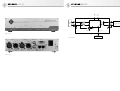
Indicators (Fig. 1)
Power
Indicates that the equipment is ready for opera-
tion. During the startup process, the indicator
shines less brightly.
Data Valid
Indicates a valid AES 42 data stream from the mi-
crophone to the DMI-2.
Sync Locked
Indicates synchronization of the microphone with
a master word clock. The indicator blinks while
the microphone is being synchronized. It shines
continuously when the microphone has been suc-
cessfully synchronized.
•
•
•
•
•
•
•
•
•
Ext Word Clk
Indicates an external word clock. The indicator
does not light up if no external word clock signal
is detected. The indicator blinks if a signal is pres-
ent at the external work clock input but synchro-
nization has not (yet) been achieved. The indica-
tor shines continuously when the DMI-2 has been
successfully synchronized with the external word
clock. Prolonged blinking of the indicator means
that although a signal is present at the word clock
input, it has not been interpreted as a valid signal;
the cause may be an invalid word clock frequency
(+/-50 ppm) or very high jitter values.
Ports (Fig. 2)
Master Clock In/Out
In digital studio setups, a central master word
clock is usually used for synchronizing the con-
nected equipment. The DMI-2 automatically syn-
chronizes itself with this external word clock as
soon as such a signal is detected at the word clock
input (BNC, 75 ohms).
If there is no valid word clock signal at the input,
the DMI-2 automatically activates an internal
word clock generator. The word clock frequency
corresponds to the sampling rate of the synchro-
nously operated microphones (see “Synchroni-
zation” section). The signal provided for other
equipment at the Master Clock Out word clock
port is therefore the external word clock signal
that has been received or the internally generated
word clock signal.
Even in the absence of power, an external word
clock signal will be transferred by the DMI-2 di-
rectly to the Master Clock Out port. If no cable has
been attached to the output of the external word
clock, an automatic termination (75 ohms) is ef-
fective at the word clock input.
For hardware version 03 or above:
An AES 11 signal can also be used as an exter-
nal word clock signal.
Even in the case of external synchronization,
the internal (VCXO) clock generator remains
active and is synchronized with the external
word clock by means of a phase-locked loop
(PLL). This provides very eff ective jitter sup-
pression.
•
•

12
US
GB
13
US
GB
AES 42 In
This is a 3-pin XLR input for connecting a digital
microphone.
AES/EBU Out
This is a 3-pin XLR output for the AES/EBU output
signal. See the “XLR cables” section for permis-
sible maximum cable lengths depending upon the
selected sampling rate.
The AES/EBU signal includes 2 standard audio
channels (stereo left and right).
In the case of synchronous operation with two
mono microphones (see “Synchronization” sec-
tion), the audio data are distributed as follows be-
tween the audio channels of the AES/EBU output
signal:
Channel 1 AES/EBU Out
Left: Microphone 1
Right: Microphone 2
Channel 2 AES/EBU Out
Left: Microphone 2
Right: No signal
In all other cases, the following assignment ap-
plies:
Channel 1 AES/EBU Out
Left: Microphone 1
Right: No signal
Channel 2 AES/EBU Out
Left: Microphone 2
Right: No signal
Control Bus
RJ-45 ports are provided for connecting a control
device, which is generally a computer (PC or Mac).
Standard Ethernet (patch) cables are used as con-
necting cables: Shielded Twisted Pair (STP) or Un-
shielded Twisted Pair (UTP).
Data transfer is eff ected via an RS 485 interface
with an additional power-out pin, for the optional
supply of an external control device.
Attention: The RJ-45 ports of the DMI-2 must not
be connected to an Ethernet.
The two RJ-45 ports are connected in parallel, in
order to permit cascading and computer opera-
tion with multiple DMI devices.
The DMI-2 is connected to the USB port of a PC or
Mac. A USB/RS 485 converter is supplied for this
•
•
•
•
purpose. This permits use of the plug-and-play ca-
pability of available USB ports together with the
much longer cable lengths (at least 100 m) that
are possible with an RS 485 connection.
ID [device address]
The device address is set by means of a coding
switch on the back of the device. If multiple DMI
devices are cascaded and controlled together,
they must have diff erent device addresses (IDs).
The addresses that can be used are dependent
upon the RCS control software employed. Cur-
rently, only the addresses 0, 1, 2 and 3 are permit-
ted (see also Section 5, “Setup”).
Attention: The device address should be changed
when the DMI is not supplied with power, since
the new address will not take eff ect until the next
time the device is switched on.
Please see the RCS control software operating
manual for information concerning the mode of
operation and assignment of device addresses.
Attention: On the front of the device is an open-
ing labelled “ID”. Here there is a push-button for
various future functions, which will include a
convenient means of setting the device address.
However, at present this button is not yet opera-
tional.
User Port
This permits direct control of microphone func-
tions by means of external switch contacts or
logic signals.
The assignments of the 9 pins are as follows (low-
active):
Pin 1 Channel 1 “Light 2” off (red LED, currently
only for the D-01 Solution-D microphone)
Pin 2 Channel 1 “Light 1” off (blue LED of Solu-
tion-D microphones)
Pin 3 Channel 1 mute switched on
Pin 4 Reserved
Pin 5 Ground
Pin 6 Channel 2 “Light 2” off (red LED, currently
only for the D-01 Solution-D microphone)
Pin 7 Channel 2 “Light 1” off (blue LED of Solu-
tion-D microphones)
Pin 8 Channel 2 mute switched on
Pin 9 Reserved
The pins can be controlled via contact with
ground, or alternatively by means of logic outputs
(TTL logic level). For example, in the case of mut-
ing, the mute can be activated and the red LED
switched off via a single contact (e.g. for the “On
Air” function).
Attention: The respective switch function is ac-
tivated only when “User Port” has been selected
in the RCS control software for the control of the
relevant function.
4. Equipment supplied
DMI-2 Digital Microphone Interface
USB 485 converter
USB cable
RJ-45 cable
Power cable
Operating manual
CD with RCS software and USB driver
5. Setup
The following steps are to be carried out for the
initial installation of a digital microphone system
consisting of the microphone, the DMI-2 Digital
Microphone Interface, and the RCS control soft-
ware.
First install the RCS control software and the as-
sociated drivers on your computer.
The minimum requirements for operation of the
RCS control software on the computer are:
Computer with Windows 98 SE, ME, 2000 or
XP operating system, or Mac OS with PPC (ver-
sion 8.6 or higher, and CarbonLib version 1.6
or higher)
A free USB port
10 MB of free hard disk space
Graphics resolution of 1024 x 768 or more
HiColor or TrueColor
CD-ROM drive
Mouse and keyboard
Adobe Acrobat Reader (only for the online
manual)
Start the setup program on the accompanying
CD-ROM (Windows: “Setup”; Mac OS: “Install
RCS”) and follow the instructions displayed on
the screen.
•
•
•
•
•
•
•
•
•
•
•
•
•
•
•
Attention:
Administrator rights are required for installa-
tion with Windows 2000/XP or Mac OS X.
The USB 485 converter must not be attached to
a computer USB port until after the RCS soft-
ware has been installed.
USB driver installation
After the RCS has been installed, the USB 485
interface converter must be connected to a com-
puter USB port. This ensures loading of the sup-
plied USB driver, which is required for operation
of the converter. In the Windows operating sys-
tem, if there is a query regarding the storage loca-
tion of the driver fi les, the CD-ROM drive should
be selected. Before confi rmation, ensure that the
installation CD-ROM has been inserted into the
drive.
Other connections
Using a patch cable, connect the USB 485 con-
verter to one of the RJ-45 ports (control bus) of
the DMI-2.
Set the device address (ID) of the DMI-2 (using
the coding switch on the back of the DMI). Ad-
dresses should be assigned beginning with “0”.
The addresses 0 to 3 are currently supported by
the RCS.
Attention: The ID is detected only during startup
of the DMI-2. Therefore, switch the power supply
off and then back on again after changing the ID,
so that the change will be detected. (Refer to the
“ID” section, page 11)
Connect the microphone, the DMI-2 and the sub-
sequent device (e.g. mixing console) by means of
XLR cables (see “XLR cables” section).
If the DMI and the connected microphones are
to be synchronized with an external master word
clock, use a BNC cable to connect the master word
clock port to the Word Clock input of the DMI-2.
If multiple DMIs are used, they can be cascaded
via the control bus. For this purpose, use an RJ-
45 patch cable to connect the second RJ-45 port
of the initial DMI to one of the RJ-45 ports of the
second DMI, etc.
If necessary, also transfer the word clock signal to
additional DMIs, via the BNC output. Connect the
DMI-2 to the power supply network.
•
•

14
US
GB
15
US
GB
Start the RCS program, or if necessary restart it, if
the program was already on.
Attention: The DMI-2 must always be switched on
before the RCS is started, so that the DMI-2 will be
detected by the PC or Mac. While the RCS is op-
erating, the cable connecting the computer to the
USB 485 converter must not be disconnected, so
as to prevent uncontrolled behavior of the com-
puter. This requirement is due to the specifi ca-
tions of the USB interface.
Long modulation cables and multiple connections
lead to a drop in the microphone supply voltage
and to a deterioration of jitter behavior, particu-
larly in the case of high sampling rates. Therefore,
if possible, use continuous cable between the mi-
crophone and the DMI-2, and between the DMI-2
and subsequent equipment. For longer distances
use AES/EBU cable exclusively (with an imped-
ance level of 110 ohms).
Ensure that the microphone and all devices in
the digital signal chain are synchronized. Micro-
phones connected to the Neumann Digital Micro-
phone Interface should always be operated in syn-
chronous mode, whether or not sample rate con-
verters are used in the subsequent signal chain.
This permits very eff ective jitter suppression in
the DMI (for hardware version 03 or above). In
addition, the output of two microphone signals as
an AES 3 stereo signal is possible only if the mi-
crophones are synchronized with one another.
When connecting cables, ensure that the connec-
tors are locked correctly.
Run the cables in such a way that there is no risk
of tripping over them.
Software updating
The software in the DMI-2 and in Neumann micro-
phones is updatable. Future updates can be car-
ried out without opening the device, via the RCS
control software (see RCS Operating Manual).
6. Shutdown
Before switching off the microphones or discon-
necting the cables, reduce the volume of con-
nected equipment.
When disconnecting a cable, always pull only on
the connector and not on the cable itself.
7. Technical data
Permissible atmospheric conditions
1)
Operating temperature .....................0 °C to +45 °C
Storage temperature .....................–20 °C to +70 °C
Relative humidity ...................max. 90 % at +20 °C
Inputs: ............2 x XLR 3 F complying with AES 42,
Audio data in accordance with
AES/EBU (AES 3) data format,
Phantom power (DPP),
Remote control data
Phantom power
(DPP): .................+10 V, max. 250 mA per channel,
short-circuit protected
Remote control data: ......................... Pulses (+2 V),
superimposed on the
phantom power,
approx. 750 bits/s
Outputs: ............................... 2 x XLR 3 M, AES/EBU
(AES 3) data format
Sampling rates supported: ........ 44.1 kHz, 48 kHz,
88.2 kHz, 96 kHz,
1 7 6 . 4 k H z * , 1 9 2 k H z *
Synchronization: ..........................AES 42 – Mode 1
and Mode 2
Mode 1: .............................. Asynchronous mode,
microphone clock free-running
at selected word clock frequency;
a sample rate converter (SRC)
is required at the receiver
Mode 2: ............................... Synchronous mode,
clock control eff ected via PLL.
If there is no external word clock,
the internal word clock generator
is automatically activated.
Word clock input ...............................................BNC
Vin ....................................... >250 mV at 75 ohms
Word clock output .............................................BNC
Vout .................................approx. 2 V at 75 ohms
Internal word clock
generator: ....................................44.1 kHz, 48 kHz,
88.2 kHz, 96 kHz,
176.4 kHz*, 192 kHz
2)
Accuracy:....................................................±25 ppm
Indicators:...................................................... Power
Data Valid (microphone),
Sync Locked,
Ext Word Clock
1)
All values are for non-condensing moisture.
2)
only for DMI-2, hardware version 03 or above
Control bus: ....................................2 x RJ-45 ports;
connection to computer USB port
via the Neumann USB 485
interface converter;
connected in parallel
for the purpose of cascading
Data format: .......................RS 485 with additional
power-out pin (approx. +11.3 V)
Device address (ID): ........... 0 to 15, adjustable via
coding switch on the back
of the device
User port: .............................................9-pin sub-D,
3 switch functions per channel
Power supply: .................90 V to 240 V; 50/60 Hz
Power consumption: .................................... <30 VA
Dimensions: .............. (W x H x D) 218 mm x 56 mm
x 163 mm
Weight: ..............................................approx. 1.4 kg
8. Additional information
8.1 AES 42
This standard is based upon the use of a 2-line
balanced cable (AES/EBU cable; for short con-
nections conventional analog cable can also be
used). The power supply for digital microphones
is defi ned as Digital Phantom Power (DPP) with
+10 V and max. 250 mA. Modulation of the phan-
tom voltage generates a remote control data
stream which is transmitted to the microphone
(as +2 V pulses).
The data format of the digital audio signal trans-
mitted from the microphone complies with the
AES/EBU (AES 3) standard. The user bits defi ned
in this standard are intended for the transmission
of various types of information. The AES 42 stan-
dard defi nes the signifi cance of these user bits
with regard to digital microphones. In the DMI-2,
these data are separated from the audio signal
and are transferred to the control bus, which
serves as an interface for a computer or control
device.
Fig. 3 shows a simple functional diagram of a mi-
crophone interface with an AES 42 input and an
AES/EBU output.
8.2 XLR cables
The length of cable that can be used from a digital
Neumann microphone to the DMI-2 is dependent
upon the type of cable and upon the sampling rate
(word clock frequency) selected. For cable lengths
of up to 100 m with a sampling rate of 44.1 kHz or
48 kHz, high-quality “analog” XLR 3 cable (e.g.
the IC 3 cable supplied by Neumann) can be used.
For greater cable lengths, the use of AES/EBU ca-
bles [110 ohms] is required. If AES/EBU cables are
employed, the following cable lengths can typi-
cally be used: Up to 300 m with a sampling rate of
44.1 kHz or 48 kHz; 200 m with a sampling rate of
88.2 kHz or 96 kHz; 100 m with a sampling rate of
176.4 kHz or 192 kHz.
Attention: If long cables are used to connect the
microphone with the DMI-2, the DC resistance of
the cables must not exceed a certain maximum
value, since an excessive DC resistance would re-
sult in an impermissible voltage drop in the phan-
tom power. The following formula applies:
Rc/2 + Rs < 18 ohms
Rc = DC resistance of the individual cable
core,
Rs = DC resistance of the shield or the GND
return line.
The length of cable that can be used from the DMI-2
to subsequent equipment (e.g. a digital mixing
console) is substantially dependent upon the
technical features of the subsequent equipment.
Thus no specifi c statements can be made concern-
ing the cable length. In case of doubt, the use of
AES/EBU cables [110 ohms] is recommended.
8.3 Operation without the RCS control software
All of the settings which are in eff ect when the
DMI-2 is switched off are stored internally, and
are automatically sent to the microphone when
the equipment is switched on again. The most
recent microphone settings are restored, without
requiring a connection to the control device (PC
or Mac).
The same procedure is followed if a microphone is
connected to the DMI-2 later, after the DMI-2 has
already been switched on.
When the RCS control software is started, the con-
fi gurations stored there for all of the microphone
channels are compared with the settings stored in
the DMI-2. If diff erences are detected, a menu is
displayed that asks which confi guration is to be
used (see RCS Operating Manual).

16
US
GB
17
US
GB
8.4 Synchronization
The AES42 standard describes the following two
modes for synchronizing the microphone with the
receiver (e.g. a mixing console or the DMI-2 Digi-
tal Microphone Interface).
Mode 1: The microphone operates asynchronous-
ly, using the sampling rate of its internal quartz
oscillator. In this case, a sample rate converter is
required at the receiver.
Attention: This mode should be used only when
it is not possible to use mode 2 synchroniza-
tion, since signal quality can be expected to be
impaired by standard sample rate converters (in
terms of dynamic range and latency time).
Mode 2: The microphone operates synchronously
with a master word clock. This can be an exter-
nal word clock, or the internal word clock of the
DMI-2. In this case, a frequency/phase compari-
son with the master word clock is carried out in
the AES 42 receiver. A control signal is generated
which is transmitted via the remote control data
stream to the microphone, where it controls the
frequency of the internal quartz oscillator.
Via the BNC output, the internal word clock gen-
erator can be used to synchronize additional
DMIs and connected equipment, such as a mixing
console.
9. Troubleshooting
Problem
▶
Possible causes
▶
Solution
The RCS does not indicate that a
microphone is switched on and
connected to the DMI, even though
the “DATA VALID” LED on the DMI
is lit up.
The DMI is not recognized by the
RCS software. – Cause:
The DMI was not switched on
at the time when the RCS was
started.
Do not start the RCS until the DMI
has been switched on; or execute
the command Options/DMI and
then close the window again.
An ID has been used that is not
currently supported by the RCS,
or the same ID has been used for
more than one DMI.
Currently only the IDs 0, 1, 2 and
3 are supported. Set the ID by
means of the coding switch on the
back of the DMI; each DMI must
have a diff erent ID!
The ID has been changed while the
DMI was in operation.
After an ID is changed, the DMI
must be restarted. Then restart
the RCS; or execute the command
Options/DMI and then close the
window again.
Incorrect interface setting (USB,
COM1 or COM2).
Select the correct interface in the
RCS via the command Options/
Communication.
The “Ext. Word Clk” LED is not lit
up, even though an external word
clock has been connected.
No word clock signal has been
detected.
Check the source of the word clock
signal and the cable connection.
The “Ext. Word Clk” LED blinks
continuously. (Blinking for a short
period following activation of an
external word clock is normal, and
indicates that the synchronization
process is being carried out).
A word clock signal is present,
but has not been interpreted as a
valid signal. This can occur, for ex-
ample, if the word clock frequency
deviates by more than ±50 ppm
from the nominal value.
Check the word clock frequency or
select another source for the word
clock signal. Alternatively, remove
the external word clock and use
the DMI internal word clock as the
master word clock for the signal
chain.
Problem
▶
Possible causes
▶
Solution
The “DATA VALID” LED is not lit up,
even though a microphone is con-
nected and switched on. (The RCS
“AES 42 PWR” display is lit up).
No valid data stream – Cause:
The microphone cable connection
is faulty or too long.
Check to ensure a continuous
cable connection.
Comply with the recommended
maximum cable length and
required cable quality, as appli-
cable for the selected word clock
frequency. Avoid unnecessary
transition points (connectors). See
Section 8.2, Cables.
The microphone is defective. Use a microphone that is in good
working order.
The “SYNC LOCKED” LED blinks
continuously. (Blinking for a short
period during the synchronization
process is normal).
The microphone has not been
synchronized because the se-
lected word clock frequency is not
supported.
Select a word clock frequency that
it is supported by all of the con-
nected microphones.
The “SYNC LOCKED” LED is not lit
up.
The microphone is operating in
asynchronous mode. (This is indi-
cated by the letter “a” preceding
the frequency display in the RCS
word clock window).
Set a sampling rate for synchro-
nous mode or set “Sync to Ext.
Word Clk”.
The microphone supports only
“mode 1” in accordance with the
AES 42 standard, i.e. it cannot be
synchronized.
Use a microphone that can be
synchronized (e.g. any Neumann
Solution-D series microphone).
Functions cannot be controlled via
the user port.
Control via the user port has not
been activated.
In the RCS system menu, “Func-
tion controlled by user port”
must be activated for the relevant
functions.

Abb. 1 / Fig. 1
Abb. 2 / Fig. 2
Digital
(Computer)
Receiver
IN
OUT
AES42 AES/EBU
DPP(+10V)
Mic.
Control Data + Control Data
Device
(e.g. Mix. Console)
Word Clock
Control Bus
DPP
Control
Abb. 3 / Fig. 3

Irrtümer und technische Änderungen vorbehalten • Errors excepted, subject to changes
Printed in Germany • Publ. 09/06 514791/A01
Konformitätserklärung
Die Georg Neumann GmbH erklärt, dass dieses Gerät
die anwendbaren CE-Normen und -Vorschriften erfüllt.
®
Neumann ist in zahlreichen Ländern eine eingetragene
Marke der Georg Neumann GmbH.
Declaration of Conformity
Georg Neumann GmbH hereby declares that this device
conforms to the applicable CE standards and regulations.
®
Neumann is a registered trademark of the
Georg Neumann GmbH in certain countries.
Further product names used here are trademarks or registered trademarks of the respective manufacturers and here-
with will be accepted.
-
 1
1
-
 2
2
-
 3
3
-
 4
4
-
 5
5
-
 6
6
-
 7
7
-
 8
8
-
 9
9
-
 10
10
-
 11
11


Ask a question and I''ll find the answer in the document
Finding information in a document is now easier with AI
in other languages
- Deutsch: Neumann DMI-2 Benutzerhandbuch
Related papers
-
Neumann TLM 103 D User manual
-
Neumann D-01 User manual
-
Neumann KH 80 DSP Operating instructions
-
Neumann TLM 170 R User manual
-
Neumann KM185 Stereo Set Owner's manual
-
Neumann U87 Ai Studiomikrofon User manual
-
Neumann TLM 103 Owner's manual
-
Neumann TLM 127 User manual
-
-
Other documents
-
Smart 26-01-01-0001 Datasheet
-
 Mutec MC 2 Owner's manual
-
Neumann.Berlin KM 84 User manual
-
-
-
-
-
RCS UR-116 Owner's manual
-
-
