Page is loading ...

SA5 E
36 Zone Wirefree Alarm System
with Voice Dialler
Installation and Operating Instructions
1
2
3
4
5
6
8
7
0
9
ESC
POWER
ALARM STATUS
A
LARM MEMORY
/ TEL MESSAGE
LINE STATUS

Kit Contents 3
Introduction and Overview
4
Multiple Users
4
System Arming
4
Zones
4
Entry/Exit Delay
4
Quick Set
4
Final Exit Set Zone
4
Walk Through
Zone
4
Omit Zone
5
Zone Lockout
5
Event Log
5
Chime
5
Voice Dialler
5
Digital Dialler
5
Latch Key
5
Answerphone
5
Voice Memo
6
Remote System Control
6
Tamper Protection
6
Jamming Detection
6
Battery Monitoring
6
System House Code
6
Planning and Extending your Wirefree
Alarm System
7
Control Panel
8
Positioning the Control Panel
8
Installing the Control Panel
8
Setting the Control Panel House Code
10
testing the Control Panel and Remote Control
10
Remote Control Unit
10
Setting the Remote Control
11
Passive Infra-Red (PIR) Movement Detectors
11
Choosing a p
osition the PIR Detector
11
Installing and configuring the PIR Detectors
12
Testing the PIR Detectors
13
Magnetic Contact Detectors
14
Installing and setting the Magnetic
Contact Detectors
14
Testing the Magnetic Contact Detectors
15
External Solar Siren
15
Positioning the Solar Siren
1
6
Installing the Solar Siren
16
Setting the Solar Siren
16
Initial
Power-Up of the Solar Siren
17
External Connections
18
Testing the System
18
Walk Test
19
Alarm test
19
Wirefree Siren Service ON/OFF
19
V
oice Dialler Test
19
D
igital Dialler Test
19
Factory Default Settings
20
Reset Factory Default Conditions
21
Programming Instructions
22
User Setup
22
System Setup
23
Zone Setup
26
Voice Dialler Setup
28
Full Arm Setup
30
Part-Arm 1 Setup
31
Part-Arm 2 Setup
32
Time & Date Setup
32
Latch Key Setup
33
Home Automation Setup
34
Answer Phone Setup
34
Remote Manager
Setup
34
Operating Instructions
35
Arming the System
35
Arm 35
Part-Art 1
35
Part-Art 2
35
Disarming the System
36
Quick Set
36
Omit Zone
36
Personal Attack (PA) Alarm
36
Tamper
36
Chime
36
Event-Log
36
Voice Memo
37
Replay Messages
37
Remote System Control
37
Battery Monitoring
38
Maintenance
39
Alarm Record
40
Troubleshooting
41
Extending your Alarm System
43
Component Specification
44
Page No. Page No.
Contents
2

3
Alarm Components:
1 x 36 Zone LCD Control Panel
2 x PIR Movement Detector
2 x Magnetic Contact Detector
1
x Remote Control
1 x External Solar Siren
Also included:
Power Supply Adaptor
Telephone Connection Lead
Installation & Operating Instructions
Fixing pack
Batteries included:
x
3
6
V/1.2Ahr Sealed lead acid
battery
(for Control Panel and
External Solar Siren)
x 2
9V PP3 Alkaline battery
(for PIR Movement Detectors)
x 5
3V CR2032 Lithium cells
(for Remote Control and
Magnetic Contact Detectors)
Important: Please check all items listed above are included in the package.
Kit Contents
External Solar Siren
(SASS E)
Note: Diagrams are for illustration purposes only actual appearance may vary.
1
2
3
4
5
6
8
7
0
9
E
SC
POWER
A
LARM STATUS
ALARM MEMORY
/ TEL MESSAGE
L
INE STATUS
Control Panel
(SA5CU E)
Magnetic Contact
Detector
(SAM E)
Remote
Control
(SAR E)
PIR Movement
Detector
(SAP E)

Multiple Users
The system allows for up to 6 User Codes and a
M
aster User Code to be configured. This allows the
s
ystem Event Log to maintain a record of which users
have armed and disarmed the system. Each user will
have a different User Code. In addition a 4 second
voice recorder facility enables the users name to be
recorded for use with the Latch-Key facility.
Only the Master User has access to the programming
functions and is able to configure the system.
Note: Any Remote Control Units on the system will
be recorded as User 6.
System Arming
The system has a full ‘Arm’ and two ‘Part-Arm’
modes. ARM will ‘Arm’ all zones while the ‘Part-Arm’
modes will only arm the zones that are enabled for
the particular part-arm mode.
For example:
The system could be configured such that during night
time, ‘Part-Arm 1’ would arm only zones protecting
the lower floor and outbuildings leaving the upper floor
free for movement without triggering the alarm.
During the day while the property is occupied ‘Part-
Arm 2’ would arm only the zones protecting the
outbuildings. However, when the property is left un-
occupied, the full ‘Arm’ mode will arm all zones to
protect the entire property, (i.e. upper and lower floors
and outbuildings).
Zones
The system incorporates 32 wireless Alarm Zones for
the connection of the system detectors that are used
to independently monitor different areas of the
property. In addition to standard intruder protection,
each zone may also be configured to operate in one
of four other modes:
- 24-hour Intruder mode
provides 24 hour intruder protection for areas
where continuous monitoring is required, (e.g.
gun cupboards).
- Fire mode
provides 24 hour monitoring of any Fire/Smoke
detectors incorporated into the system.
- Test mode
allows a zone to be monitored while the system is
armed. If a detector on a test zone is triggered
an entry will be recorded in the Event Log but an
alarm will not occur.
In addition there is the facility to connect 4 hard
wired zones to the Control Panel, each of which is
fully configurable with the same features as the
wirefree zones (1-32).
Entry/Exit Delay
When the system is armed with the Exit-Delay
enabled, no alarm signal from any detector on an
active zone will be able to initiate an alarm until the
Exit-Delay has expired. This enables the system to
be armed from within the property and allows time
for the user to exit the property without triggering an
alarm. If the Exit-Delay is disabled then detectors on
active zones will immediately be able to initiate an
alarm as soon as the system begins to arm.
The system Exit-Delay may be configured for between
10 to 250 seconds or disabled completely.
If a detector on a zone with its Entry-Delay enabled
is triggered, then an alarm condition will not occur
until the Entry-Delay period has expired. This allows
time for the user to re-enter the property and disarm
the system before an alarm condition occurs.
Generally only the zones on the main entry route to
the property will be configured with an Entry-Delay.
The remaining zones would be configured with their
Entry-Delay disabled allowing them to immediately
initiate an alarm a detector on the zone is triggered.
The Entry-Delay for each zone may be configured for
between 10 to 250 seconds or disabled completely.
Quick Set
The system may be fully armed in 5 seconds using
the quick set facility, overriding the programmed exit-
delay. This is useful for setting the system at night
when the exit-delay warning beep will be silenced
after just a few seconds.
Final Exit Set Zone
Triggering a detector on a Final Exit zone during the
exit-delay will cause the delay to reset to 5 seconds
with the system arming 5 seconds later.
Walk Through Zone
This feature may be used for detectors located on
the main entry route to the Control Panel. When the
Introduction and Overview
4

s
ystem is armed and a zone configured as a ‘Master
Walk Through’ zone is triggered, the zones Entry-
Delay will start. Any zones configured as ‘Slave Walk
Through’ will be disabled to allow free access to the
Control Panel to disarm the system before the Entry-
Delay expires an alarm occurs.
If access is gained via a zone that is not configured as
‘Master Walk Through’, the ‘Slave Walk Through’ zones
will operate as normal according to their programmed
Entry-Delay setting.
Note: A zone set as a ‘Master Walk Through’ zone
must be configured with an Entry-Delay.
Omit Zone
A zone may be temporarily omitted when the system
is armed using the Omit feature. When the system is
next disarmed any zones set to Omit will be cancelled.
Zone Lockout
If a detector on an active zone is triggered while the
system is armed an alarm condition will occur. After
the programmed alarm duration has expired the alarm
will stop and the system will automatically reset.
Subsequent detectors triggered will again initiate an
alarm condition. If a single zone initiates an alarm
condition more than three times then that zone will be
‘Locked Out’ and any further alarm signals from that
zone will be ignored until the system is disarmed.
Note: The ‘Zone Lockout’ feature can be disabled
if required.
Event Log
The Control Panel incorporates a memory capable of
storing the last 50 system events. This enables the
user to see which user has Armed/Disarmed the
system and if and when any alarms occurred. The
time, date and details of the event type will be
recorded for each system event.
Chime
Chime is a low security facility for use when the
system is in Standby mode. If the Chime feature is
ON, and a detector on a zone that has its Chime
function enabled is triggered, the internal sounder
will produce a low volume warning tone. A typical
use of the Chime function would be to warn that a
door or particular area has been accessed.
Voice Dialler
I
f the Voice Dialler is enabled and an alarm condition
occurs, the system will call for help using your recorded
alarm messages and up to four telephone numbers.
When an alarm condition occurs, the telephone voice
dialler (if enabled) will call the first enabled number in
the calling sequence and replay the recorded alarm
messages for the configured ‘Play Time’. The recipient
must acknowledge the message by pressing the
button on their telephone keypad. If the call is
unanswered or an acknowledgment is not received
then the next active number in the dialing sequence
will be called. The dialler will continue calling each
number in turn until either all numbers in the sequence
have been dialed the set number of times or the
sequence is cancelled/acknowledged by the recipient.
Digital Dialler
As an alternative to the Voice dialler the system may be
configured to interface with a central monitoring station.
Latch Key
When the system is disarmed the Latch-Key
facility, if enabled, will call the first latchkey phone
number and replay the user message (recorded
under user setup) for the set ‘Play Time’. The recipient
must acknowledge the message by pressing the
button on the telephone keypad. If the call is
unanswered or an acknowledgment is not received
then the second latchkey phone number will be called.
The voice dialler will continue calling each number in
turn until each number has been dialed the set number
of times or the sequence is cancelled/acknowledged
by the recipient.
For example, the latchkey facility is useful to inform
parents that a child has returned from school and
disarmed the system.
Answerphone
The Control Panel includes an answer-phone facility.
The answerphone will record and store a maximum
of 6 messages with each message being limited to a
30 seconds duration.
Messages may be retrieved either direct from the
Control Panel or by dialing into the system from a phone.
5

Voice Memo
In addition it is also possible to record messages at
the Control Panel using the ‘Voice-Memo’ facility.
E
ach voice-memo message is limited to a maximum
duration of 30 seconds and counts as an answer
phone message.
Remote System Control
It is possible to dial into the system via the telephone
to interrogate the system status and to have basic
control over the system, (e.g. to Arm and Disarm the
system). You may also activate the microphone on
the control panel to Listen-In to what is happening in
the protected property.
Answer phone and Voice-memo messages may also
be accessed remotely.
Tamper Protection
All system devices (except Remote Control Units)
incorporate Tamper protection features to protect
against unauthorized attempts to interfere with the
device. Any attempt to remove the battery cover
from any device (except a Remote Control) or to
remove the Solar Siren or Control Panel from the
wall will initiate an alarm condition even if the
system is Disarmed (unless the system is in Test or
Programming modes).
Jamming Detection
In order to detect any attempts to illegally jam the
radio channel used by your alarm system, a special
jamming detection function is incorporated into the
Control Panel and also on some Solar Siren models.
If this feature is enabled, and the radio channel is
jammed continuously for 30 seconds, when the
system is armed, the Solar Siren will emit a pre-alarm
series of rapid bleeps for 5 seconds. If the jamming
continues for a further 10 seconds or more a full
alarm condition will occur. In addition if the system
is jammed for more than three periods of 10 seconds
in a 5 minute interval, this will also generate a Full
Alarm condition.
The jamming detection features in the Control Panel
and Solar Siren operate independently.
The Jamming Detection circuit is designed to
permanently scan for jamming signals. However, it
is possible that it may detect other local radio
i
nterference operating legally or illegally on the same
frequency. If you are planning to operate the
J
amming Detection feature we recommend that you
wait at least 30 days before activating this feature,
this will allow time for you to become familiar with the
operation of your system.
Battery Monitoring
All devices powered by non-rechargeable batteries
incorporate a battery level monitoring feature which
warns when the battery status is low.
In addition the Control Panel will also indicate a low
battery status on any PIR Detector or Magnetic
Contact Detector on the System.
Batteries on any device indicating a low battery
status must be replaced immediately.
System House Code
In order to prevent any unauthorized attempt to
operate or disarm your system, you must set your
system to accept radio signals only from your own
devices. This is done by setting a series of eight
miniature (DIP) switches in all devices (except the
Control Panel) to the same ON/OFF combination (the
House Code) selected by the user/installer. The
Control Panel is then programmed to operate only
with devices set to this House Code.
All Detectors and Remote Control Unit(s) must be set
with the same House Code in order for the system to
operate correctly.
Inside the Siren, Detectors and Remote Control Unit
is a series of 8 DIP switches.
The House Code is set by moving each of the 8
switches in each device to the same randomly
selected ON/OFF sequence. When setting the DIP
switches, ensure that each switch ‘clicks’ fully into
position. Use the tip of a ballpoint pen or a small
screwdriver to move each switch in turn.
Note: It is recommended that the system House
Code is always reset to a code other than the factory
default.
6
e.g.
Switch 1
= set to ON
position
ON
ECE
1 2 3 4 5 6 7 8

7
The example below shows a typical property
incorporating the suggested positions for the
Control Panel, PIR and Magnetic Detectors for
optimum security.
Use this as a guide for your installation in conjunction
with the recommendations contained in this manual
for planning your intruder alarm system.
Before attempting to install your Alarm System it is
important to study your security requirements and
plan your installation.
The alarm system may be extended at any time to
provide even greater protection by fitting additional
devices to meet your personal security needs.
Planning and Extending your Wirefree Alarm System
LCD
Control
Panel
Remote
Control
PIR Movement
Detector
SHED
LOUNGE
GROUND FLOOR
GARAGE
KITCHEN
HALL
DINING
ROOM
Back Door
Magnetic
Contact
Detector
PIR
Movement
Detector
PIR
Movement
Detector
External
Solar Siren
Magnetic Contact
Detector
PIR Movement
Detector
PIR Movement
Detector
1
2
3
4
5
6
8
7
0
9
ESC
POWER
ALARM STATUS
A
LARM MEMORY
/ TEL MESSAGE
LINE STATUS

Control Panel
8
Positioning the Control Panel
When choosing a suitable location for the Control
Panel, the following points should be considered.
1.
The Control Panel should be located in a position
out of sight of potential intruders and in a safe
location, but easily accessible for system operation.
2.
The Control Panel should be mounted on a sound
flat surface to ensure that the rear tamper switch
on the Control Panel is closed when the Panel is
mounted. The Control Panel should be mounted
at a convenient height of between 1.5 and 2m and
in a position where it will be seen each day.
Note: If small children are in the household, a
further consideration should be given to keeping
the units out of their reach.
3.
It is recommended that the Control Panel should
be positioned such that the Exit/Entry tone
(emitted by the Control Panel) can be heard from
outside the property.
4.
The Control Panel should be mounted within a
protected area so that any intruder cannot reach
the Control Panel without opening a protected
door or passing through an area protected by a
PIR Detector when the system is armed.
5.
The Control Panel must be located within reach of
a mains socket.
6.
If the telephone voice dialler is to be used then the
Control Panel will need connecting to a convenient
telephone point.
Note: It is recommended that the telephone
connection lead is not extended beyond 5m
before connecting to a telephone master or
secondary outlet.
7.
Do not locate the Control Unit closer than 1m to
any large metallic object, (e.g. mirrors, radiators,
etc) as this may affect the radio range of the
Control Panel.
Installing the Control Panel
1.
Undo the two captive fixing screws on top of the
panel and open the cover. The cover is hinged
along the bottom edge.
2.
Unclip and remove the two back-up batteries on
either side of the panel.
3.
Hold the Control Panel in position on the wall and
mark the positions of the four fixing holes.
Remove the Panel and drill four 5mm holes and fit
the 25mm Wall Plugs.
Note: The wall plugs supplied with the product are
not suitable for plasterboard walls, if mounting the
Control Panel onto plasterboard use proprietary
wall plugs.
Important: Do not drill the fixing holes with the
Control Panel in position; as the resulting dust and
vibration may damage the Control Panel’s internal
components and invalidate the guarantee.
External view of Control Panel
1
2
3
4
5
6
8
7
0
9
E
SC
POWER
ALARM STATUS
ALARM MEMORY
/ TEL MESSAGE
LINE STATUS
L
CD Window
Status LEDs
Keypad

4.
Fit two 18mm No. 4 screws into the top holes until
almost fully home and hang the Control Panel over
the screws using the two keyhole slots in the top
corners of the panel casing.
5.
Route the cable from the Power Supply Unit up
behind and on the right hand side of the Control
Panel and connect the plug to the DC power
socket in the panel. Ensuring that the cable is not
trapped between the Control Panel and the wall.
6.
Fix the Control Panel to the wall using two 18mm
No. 4 screws in the lower two fixing holes in the
Control Panel and tighten the upper fixing screws
until they just grip the casing. Do not over tighten
the fixing screws or this may damage the casing.
7.
Ensure that the ‘Reset’ and the ‘Hard-Wired Siren
tamper detect’ jumper links are set in the OFF position.
8.
Connect battery leads to both back-up batteries
and refit batteries.
Battery 1 (left): Red lead to + battery terminal
Blue lead to – battery terminal
Battery 2 (right): Blue lead to + battery terminal
Black lead to – battery terminal
Important: Take care when connecting battery
leads to the batteries as connecting incorrectly
could damage the batteries or the Control Panel.
Note: The Power LED may flash to indicate that
the unit is being operated from the back-up
batteries and that mains supply is not present.
9.
If fitted, remove the plastic film covering the LCD
display and on the display window on the cover.
10.
Close the lid of the Control Panel and tighten the
captive fixing screws.
11.
Plug in and switch ON the Power Supply Unit, (the
Power LED should illuminate).
12.
If required, connect the Control Panel to the
telephone line using the cable supplied by
inserting small RJ11 plug into socket marked LINE
located on the bottom edge of the Control Panel.
Connect the BT plug on the other end of the lead
to an appropriate telephone outlet.
If the cable supplied is not long enough to reach a
suitable phone point then it will need extending
using a coupler and extension lead (not supplied).
9
Inside view of Control Panel
T1
T
2
GND
T3
T4
N.C.
C
N.O.
GND
GND
V+
OUT
GND
B+
G
ND
TAMP
Power Supply
Cable Route
+ Terminal
(Red Lead)
-
Terminal
(Blue Lead)
Upper
Keyhole
Fixing Hole
Lower
Fixing
Hole
External Tamper Switch
Jumper Link P51
Upper
Keyhole
Fixing Hole
+ Terminal
(Blue Lead)
Reset
J
umper
Link P1
Power
Supply
Jack
Socket
-
Terminal
(
Black Lead)

N
ote: If the Panel Tamper alarm sounds during the
installation reset the alarm by pressing:
on the Control Panel Keypad.
Setting the Control Panel
House Code
W
ith the unit in Standby mode (Power LED only
i
lluminated).
1.
Press
to put the system into Programming mode.
‘1. USER SETUP’ will be displayed.
2. Use the and buttons to scroll
through
the menu until ‘2. SYSTEM SETUP’ is displayed.
Press and ‘2-1 Learn House Code’ will be
displayed.
Press again to set the Control Panel to receive
the House code. ‘DIP SW 12345678 & H Code:
xxxxxxxx’ will be displayed.
3.
With the required House Code already configured
on the Remote Control, press the button
on the Remote Control.
When the Control Panel receives the signal from
the Remote Control the Display will change to
show the received house code on lower line of
the display beneath the corresponding DIP switch
numbers (1-8).
4.
Press
to return to Standby mode.
Testing the Control Panel and
Remote Control
1.
Press
to put the system into Test mode.
‘TEST MODE – WALK TEST’ will be displayed.
2.
Press to activate Walk Test.
‘Walk Test Waiting…’ will be displayed.
3.
Press the ‘ARM’ button on the Remote Control.
As the key is pressed the Control Panel will beep
and the type of the device and button will be
shown on the display.
P
ress the other buttons on the Remote Control in
turn, as each button is pressed the Control Panel
will beep and show the button being pressed on
the display.
4.
Test the range of the Remote Control by pressing
t
he ‘DISARM’ button on the Remote Control from
in and around the property and from all locations
where you plan to install detectors. Check that
the Control Panel acknowledges the signal from
the Remote Control each time the ‘DISARM’
button is pressed.
5.
Press to return to the top level menu of
TEST MODE.
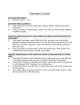
Remote Control Unit
The Remote Control Unit is used to Arm, Part-Arm and
Disarm the system.
The Remote Control Unit also incorporates a Panic
switch. Activating the Panic switch on the side of the
Remote Control will immediately initiate a Full Alarm
condition whether the system is Armed or Disarmed.
The alarm can be cancelled by pressing the ‘DISARM’
button on the Remote Control or via the Control Panel.
Any number of Remote Control Units can be used with
your system, providing they are all coded with the
same system House Code.
The Remote Control uses a CR2032 type Lithium cell
which under normal conditions will have a typical life
in excess of 1 year. Under normal battery conditions
the LED on the Remote control will illuminate only
when a button is pressed. However, under low-
battery conditions this LED will flash every time the
button is pressed. When this occurs the battery
should be replaced as soon as possible.
10
,
,
1
2
3
4
,
,
1
2
3
4
Slide up
to operate
Transmit LED
Personal
Attack
Disarm
Arm
Part-Arm
,
,
1
2
3
4
,,
ESC ESC
ESC

Setting the Remote Control
1.
Remove the front cover by undoing the small
screw on the rear of the Remote Control.
2
.
L
ocated above the battery is a row of 8 DIP
s
witches. Select and record a random combination
of ‘ON’ and ‘OFF’ positions for the DIP switches.
This will be the system House Code that enables
all elements of your transmitters to communicate
with the Control Panel.
Important: The House Code for your system should
be changed from the factory default setting.
3.
Ensure that the jumper link located immediately
below the House Code DIP switches is fitted in
position for use with this alarm system.
4.
Insert the battery under the clip ensuring that the
+v terminal faces upwards away from the PCB.
5.
Replace the front cover and fixing screw.
Passive Infrared (PIR)
Movement Detectors
PIR Detectors are designed to detect movement in
a protected area by detecting changes in infra-red
radiation levels caused, for example, when a person
moves within or across the devices field of vision.
If movement is detected an alarm signal will be
generated, (if the system and alarm zone is armed).
Note: PIR Detectors will also detect animals, so ensure
that pets are not permitted access to areas fitted with
Passive Infra Red Detectors when the system is armed.
Any number of PIR Detectors can be used with your
system, providing they are all coded with the system
House Code and are mounted within effective radio
range of the Control Panel.
T
he PIR Detector is powered by a PP3 Alkaline
battery which under normal conditions will have an
expected life in excess of 1 year. When the battery
level drops, with the PIR Detector in normal operation
mode and the battery cover fitted, the LED behind
the detection window will flash. When this occurs
the battery should be replaced as soon as possible.
Choosing a position for the
PIR Detector
The recommended position for a PIR Detector is in
the corner of a room mounted at a height between
2 and 2.5m. At this height, the PIR Detector will
have a maximum range of up to 12m with a field of
view of 110°.
The Position of the PCB inside the PIR Detector can
be set to 5 different positions to adjust the range of
the detection pattern created by the PIR Detector.
Setting the PCB in position 3 will reduce the range to
approximately 9m, with position 1 providing a range of
approximately 6m. The recommended position setting
for the PCB is in position 5.
When considering and deciding upon the mounting
position for the PIR Detector the following points
should be considered to ensure trouble free operation:
1.
Do not locate the PIR Detector facing a window or
where it is exposed to or facing direct sunlight. PIR
Detectors are not suitable for use in conservatories.
2. Do not locate the PIR Detector where it is exposed
to ventilators.
11
Battery Clip
House Code
Dip Switches
Jumper Link
Battery
Less Sensitive
More Sensitive
110°
12
10
8
6
4
2
0
2
4
6
8
10
12
0
2
4
6
metres
8
10
12
0
2
metres
Side View
Top View

3
. Do not locate the Detector directly above a heat
source, (e.g. fire, radiator, boiler, etc).
4
. Where possible, mount the PIR Detector in the
corner of the room so that the logical path of an
intruder would cut across the fan detection
p
attern. PIR Detectors respond more effectively to
movement across the device than to movement
directly towards it.
5. Do not locate the PIR Detector in a position where
it is subject to excessive vibration.
6. Ensure that the position selected for the PIR
Detector is within effective range of the Control
Panel. It is recommended that prior to installation
the Detector is set and tested with the Control
Panel in Walk Test mode to ensure that they are
within effective range.
Note: When the system is Armed, pets should not be
allowed into an area protected by a PIR Detector as
their movement would trigger the PIR Detector and
trigger an alarm.
Note: DO NOT fix the PIR Detector to metalwork or
locate the unit within 1m of metalwork (i.e. radiators,
water pipes, etc) as this could affect the radio range
of the Device.
Installing and configuring the
PIR Movement Detectors
Ensure that the Control Panel is in Test mode.
1.
Undo and remove the fixing screw from the
bottom edge of the PIR Detector. Carefully pull the
bottom edge of the Detector away from the rear
cover and then slide down to release the top clips.
2. Carefully drill out the required mounting holes in the
rear cover using a 3mm drill according to whether
the unit is being mounted in a corner or against a
flat wall.
3. Using the rear cover as a template, mark the
positions of the fixing holes on the wall.
4. Fix the rear cover to the wall using the two 18mm
No. 4 screws and 25mm wall plugs, (a 5mm hole
will be required for the wall plugs). Do not over-
tighten the fixing screws as this may distort or
damage the cover.
Note: The wall plugs supplied with the product are
not suitable for plasterboard walls, if mounting the
PIR Detector onto plasterboard use proprietary
wall plugs.
5.
When setting Dip Switches to House Code,
hold the PIR Detector ‘upside down’ as shown
in the diagram below:
Set the House Code for the PIR Detector by setting
DIP switches 1-8 of SW2 to the same ON/OFF
combination as the House Code DIP switches in all
other system devices.
6. Set the alarm zone which the Detector will operate
on by setting DIP switches 1-3 of SW3 as follows:
12
Rear Cover
Fixing Screw
Mounting Hole
Positions
Zone 1
Zone 2
Zone 3
Zone 4
Zone 5
Zone 6
DIP 1
OFF
OFF
OFF
OFF
ON
ON
DIP 2
OFF
OFF
ON
ON
OFF
OFF
DIP 3
OFF
ON
OFF
ON
OFF
ON
8
7
6
5
4
3
2
1
2
1
4
3
5
E
C
E
E
C
E
O
N
O
N
S
W
3
S
W
2
5
4
3
2
1
DIP Sw
itches
(SW2 and
SW3)
PCB
Board
(slides
up and
down to
adjust
po
sition)
ON
ECE
ON
ECE
1 2 3 4 5 6 7 8 1 2 3 4 5
SW3
SW2
Set to House Code
Zone
Settings
Walk Test
Sensitivity

7
.
DIP4 of SW3 is used to set the PIR Detector for
walk test mode, which allows the operation of the
Detector to be checked during installation without
triggering a Full Alarm.
ON Walk Test mode
OFF Normal operation
Note: On initial installation the PIR Detector should
be set into Walk Test mode ready for testing.
8. The PIR Detector incorporates a sensitivity feature
designed to compensate for situations where the
Detector may be affected by environmental
changes, (e.g. insects, air temperature, etc). This
feature is called “Detection Sensitivity” and may be
set to Standard or High Sensitivity.
Note: The higher the sensitivity the less movement
will be necessary before the PIR Detector will
trigger the alarm.
The recommended setting is Standard Sensitivity.
If set to High Sensitivity, in some cases, extreme
environmental problems could cause unattributed
false alarms. If this is experienced it may be necessary
to reset the PIR Detector to Standard Sensitivity.
Set the required detection sensitivity using DIP 5 of
SW3 as follows:
9. Connect the PP3 Alkaline battery to the battery clip.
Note: When the 9V Alkaline battery is connected
the LED behind the lens will rapidly flash for
a
pproximately 2-3 minutes until the PIR Detector
has warmed up and stabilized. The LED will then
stop flashing and turn OFF.
10. Check that the PIR Detector PCB is located and set
i
n the correct position to give the detection zone
pattern required.
To adjust the PCB position, simply slide it up or
down ensuring that the location legs are aligned with
the required position number marked on the board.
11. Refit the PIR Detector to the rear cover by offering
the PIR Detector up to the rear cover and locate
the clips in the top edge into the rear cover. Push
the lower edge of the PIR Detector into place and
refit the fixing screw in the bottom edge of the PIR
Detector to secure in position. Do not over-tighten
the fixing screws as this may damage the casing.
Testing the PIR Detectors
Ensure that the Control Panel is in Test mode.
With the PIR detector set in Test mode (i.e. Dip 4 on
SW3 ON) and mounted in position on the wall, allow
2-3 minutes for the detector to stabilize before
commencing the Walk Test.
1. Use the and buttons to scroll
through
the menu until ‘WALK TEST’ is displayed.
Press to activate Walk Test.
‘Walk Test Waiting…’ will be displayed.
2. Walk into and move slowly around the protected
area, each time the detector senses movement
the LED behind the lens will flash. In addition,
the Control Panel will beep to indicate that the
alarm signal has been received and the identity
of the zone that the detector is configured for
will be displayed.
8
7
6
5
4
3
2
1
2
1
4
3
5
E
C
E
E
C
E
O
N
O
N
S
W
3
S
W
2
5
4
3
2
1
PCB Positions
Indicator
(positions 1-5)
5
4
3
2
1
13
OFF
Standard Sensitivity
ON
High Sensitivity
PCB Position Range
1 6m
3 9m
5 12m
DIP 4 Mode Trigger reaction
o
f SW3 on LED
ON Walk • LED single flash
Test when movement
detected: implies
the sensor is set to
high sensitivity
• LED flashes three
times and illuminates
once: implies the
sensor is set to low
sensitivity
OFF Normal LED will not light up
Position (unless the battery in
the PIR is low)

If necessary adjust the detection range by
changing the mounting position of the PCB
within the PIR housing.
Note: In normal operation, the LED behind the
PIR lens will not flash on movement detection,
(unless the battery is low).
If necessary re-adjust the detection pattern by
c
hanging the mounting position of the PCB within
t
he PIR housing.
3.
Remove the back cover of the PIR detector.
The Control Panel should beep and display
‘Accessory Tamper’ to show that the detector’s
tamper switch has been activated.
4. Press to return to the top level menu of Test
Mode.
5. Reconfigure the PIR Detector for normal mode by
setting DIP4 of SW3 to OFF and refit in position
Note: When the detector is fully installed i.e. battery
cover is refitted; the unit will not detect movement
for approximately 2 minutes after each activation.
(This feature is present to conserve battery power and
maximize the battery life).
Magnetic Contact
Detectors
Installing and setting the Magnetic
Contact Detectors
Ensure that the system is in Test mode.
1.
Remove the battery cover by sliding and lifting it
off. (DO NOT use a screwdriver to lever off).
2. Remove the battery holder by carefully tilting up
the end and pulling the connector off the printed
circuit board.
3. Mount the Magnetic Contact Detector to the fixed
part of the frame along the opening edge opposite
the hinges using either the double sided adhesive
tape or screws provided.
When fixing the Magnetic Contact Detector with
screws, the top of the Detector is secured with a
keyhole slot over the screw head of the smaller pan
head screw. The bottom is secured using the 12mm
countersunk head screw fitted within the battery
compartment. Carefully drill out the centre of the
fixing screw hole in the battery compartment using
a 3mm drill. Do not over-tighten the fixing screws
as this may distort or damage the casing.
4. Fit the Magnet to the moving part of the door/
window opposite the Magnetic Contact Detector
using the two 15mm fixing screws. Ensuring that
the parallel gap between the Magnet and Detector
is less than 10mm and that the arrow on the
Magnet is pointing towards and aligned with the
mark on the top section of the Detector.
5. If an additional wired Magnetic Contact Detector is
required, this should be wired to the terminal block
provided in the battery compartment. The wired
contact should be connected using two core
(24AWG) wire of maximum length 1.5m.
Important: If an additional wired contact is not
connected, then the jumper link SW2 must be fitted for
the Magnetic Contact Detector to operate correctly.
14
Battery
Connector
Tilt and Remove
Battery Holder
and Insert
Two Batteries
Double Sided Tape
OR Screw Fixing
R
aised Head Screw
Key-hole Slot Fixing
(underside)
Small Counter-sunk
Screw Fixing
Slide Open and Lift Off
Do Not Use A Screwdriver
Detector
Magnet
Cut-out for
Cable Entry
Battery Cover
Alternative
Mounting
(Ensure
back
surfaces
are flush)
ESC

6
. Set the House Code for the Magnetic Contact
Detector by setting DIP switches 1-8 to the same
ON/OFF combination as the House Code DIP
switches in all other system devices.
7. Set the alarm zone which the Detector will operate
on with DIP switches 9-11 as follows:
8. Slide the two batteries supplied into the battery
holder, ensuring that the positive (+) side is
uppermost on each battery as it is installed.
9. Carefully refit the battery holder onto the Detector
ensuring that the spring connectors slide onto
either side of the circuit board.
10. Fit the battery cover into position on the Magnetic
Contact Detector.
Testing the Magnetic Contact
Detectors
Ensure that the Contro Panel is in Test mode.
1.
Use the and buttons to scroll through
the menu until ‘WALK TEST’ is displayed.
Press to activate Walk Test.
‘ Walk Test Waiting…’ will be displayed.
2
. Remove the battery cover by sliding off..
As the battery cover is removed the LED on the
Detector will illuminate for approx. 1 second to
indicate that the tamper switch has been
activated. In addition, the Control Panel will beep
to indicate that an alarm signal has been received
and ‘Accessory Tamper’ will be displayed.
3
. Open the door/window to detach the magnet
from the Detector. As the magnet is parted from
the detector the LED will illuminate for approx.
1 second to indicate that the Detector has been
triggered. In addition, the Control panel will beep
to indicate that an alarm signal has been
received and the identity of the zone that the
detector is set for will be displayed.
Note: In normal mode with the battery cover
fitted, the LED on the detector will not illuminate
when the detector is triggered, (unless the battery
is low).
4. If connected, operate the wired Magnetic
Contact. As the contact is opened the LED on
the Detector should illuminate for 1 second to
indicate that it has been triggered and the
Control Panel will acknowledge the alarm signal.
5. Refit the battery cover on the Detector.
6.
Press to return to the top level menu of
Test Mode.
External Solar Siren
The Siren and Solar Panel are all encapsulated within
a tough polycarbonate housing. This housing provides
full protection against adverse weather conditions.
An LED/Strobe unit is built into the siren to act as a
visible deterrent/indication that the system is active. The
Strobe LEDs will slowly and alternately flash whether
the system is armed or disarmed. However, during
an alarm condition the Strobe LEDs will flash rapidly.
An integral anti-tamper switch provides additional
security protection to the Solar Siren and will
immediately generate a full alarm should any
unauthorized attempt be made to interfere with and
remove the Solar Siren cover.
The Solar Siren is powered by a high capacity battery.
A Solar Panel mounted on the top of the housing
15
ESC
Zone 1
Zone 2
Zone 3
Zone 4
Zone 5
Zone 6
DIP 9
OFF
OFF
OFF
OFF
ON
ON
DIP 10
OFF
OFF
ON
ON
OFF
OFF
DIP 11
OFF
ON
OFF
ON
OFF
ON
ON
ECE
1 2 3 4 5 6 7 8 9 10 11 12
8mm
1
1mm
Terminal Block for Additional Wired
Magnetic Contact Detector T1
Anti-Tamper
Switch SW2
Location of
Key-hole Screw
(underside)
J
umper
Link S2
Hole for
Mounting
S
crew
Batteries
x 2
O
N
1
2 3 4 5 6 7 8 9 10 11 12
Zone
House Code
E
CE
Dip Switch
12 Not Used

c
harges the battery during daylight hours. During
darkness, only a small amount of energy is required to
operate the Solar Siren unit.
A
n Alkaline 9V PP3 battery is supplied in the Solar
Siren to boost the initial power to the unit when the
system is first activated until the Solar Panel charges
t
he main battery.
Positioning the Solar Siren
The Solar Siren should be located in a prominent
position so that it can be easily seen and heard. The
Solar Siren should be mounted on a sound flat surface
so that the rear tamper switch is not activated when
mounted. Ensure that the tamper switch does not fall
into the recess between brick courses as this could
prevent the switch from closing and give a permanent
tamper signal.
Although the Solar Siren is designed to work on any
aspect wall, for optimum performance you should
refrain from siting the unit on a north facing wall,
where possible.
Shadows cast by neighbouring walls, trees and roof
overhangs should also be avoided. If the Solar Siren
is to be mounted below the eaves, it should be
positioned a distance of at least twice the width of the
eaves overhang below the eaves. Remember that in
winter the sun is lower in the sky and you should avoid
winter shadows where possible.
The Solar Siren contains a sophisticated radio
receiver. However, reception of radio signals can be
affected by the presence of metallic objects within the
vicinity of the Solar Siren. It is therefore important to
mount the Solar Siren a minimum distance of 1m
away from any external or internal metalwork, (i.e.
drainpipes, gutters, radiators, mirrors etc).
E
nsure that the position selected for the Solar Siren
is within effective range of the Control Panel, (refer to
“Testing the Control Panel & Remote Control”).
Installing the Solar Siren
1. Remove the fixing screw from the bottom edge of
the Solar Siren Siren housing and carefully hinge off
the front cover. All electronic components are
housed within the front cover.
2. Hold the mounting plate in position and mark the
positions of the four mounting holes (a spirit level
placed on the casing will ensure a perfect level).
Drill four 6mm holes and fit the wall plugs.
3. Fit the two 30mm fixing screws in the top holes
leaving approx. 10mm of the screw protruding.
4. Fit the top keyhole slots of the mounting plate over
the screw heads. Adjust the mounting plate and
adjust the screws until they form a neat fit with the
mounting plate with minimal movement
5. Secure the mounting plate in position using the two
25mm fixing screws in the bottom fixing holes.
6.
Ensure that the Siren’s main configuration switch
on the LED Indicator board is set to "Siren".
Setting the Solar Siren
Ensure that the Solar Siren main configuration switch
if fitted on the LED strobe board is set to “SIREN” for
use with this alarm system.
Undo the 3 screws holding the DIP Switch cover in
place and remove the cover.
House Code
Under the corner cover you will find a series of 9 DIP
switches.
DIP switches 1-8 are used to set the House Code for
the siren and must be set to the same ON/OFF
combination as all other system devices.
Avoid if
possible
South
West
East
North
16
ON
1 2 3 4 5 6 7 8 9
Alarm Duration DIP switch 9
House Code
(Always change from the factory setting)

Tamper
Switch
6 Volt 1.2Ahr
Rechargeable
Battery
9 Volt PP3
Initial Power-Up
Battery
DIP Switch
Cover
C.U.
Main Configuration
Switch (in SIREN
Position)
SIREN
C.U. SIREN
P1
P2
P3
Solar Panel
ON
1
2 3 4 5 6 7 8 9
Receiver
Aerial
7.5 Volt DC
Charging Adaptor
I
nput
Beep Disable Link
Siren Disable Link
Jamming
Detection Link
P1
P2
P3
ON
1 2 3 4 5 6 7 8 9
LED/Strobe PCB
Front Cover
Locating Tabs
Printed Circuit
Board Enclosure
Siren
Alarm Duration
DIP Switch 9
House Code
DIP Switches 1-8
Inside view of Solar Siren
Note: When the Solar Siren is viewed as shown above
(Solar panel at top) the DIP switches are ‘upside down’.
Alarm Duration Limit
If required the maximum length of time that the
External Solar Siren will sound for when activated
under an alarm condition may be limited to 3 minutes
using DIP switch 9 as follows:
OFF 3 minute limit
ON 10 minutes or same as programmed
setting on Control Panel.
Beep Disable
The Solar Siren will acknowledge Disarm signals from
the Remote Control by beeping twice. It is possible to
disable the beeps if required by removing the jumper
link P2 on the circuit board.
Siren Disable
If for any reason you need to disable the Siren, remove
jumper link P3 on the circuit board. This will prevent
the Siren from sounding during an alarm condition.
However, the Siren will still beep to acknowledge
signals from the Remote Control, (provided the beep
feature is not disabled).
Once you have completed configuring the Solar Siren,
refit the DIP switch cover and replace the three cover
fixing screws. Do not over tighten the screw as this
could damage the thread.
Initial Power-Up of the Solar Siren
1. Connect the 9V PP3 initial power battery to the
battery clip.
Connect the rechargeable battery to the charging
leads. Connect the Red lead to the Red (+) terminal
and the Black lead to the Black (
-
) terminals.
Note: Once the batteries have been connected, the
Siren will be operational and it is important that the
Solar panel receives sufficient light to maintain the
battery charge. The Siren should not be operated
repeatedly during installation and testing, as this
will rapidly drain the battery. It is recommended
that the Siren be left for at least a day in order to
charge the battery before the system is armed.
17

2
. Press the anti-tamper switch, the LEDs will flash
t
ogether to indicate that the unit is operational.
3. Hinge the front cover locating tabs over the top
edge of the back plate and carefully push the base
of the siren cover into place. Secure the siren
cover in place by refitting the fixing screw in the
bottom edge of the cover. Do not over tighten the
screw as this could damage the thread.
Important: Ensure that the rear tamper switch is
closed when you fit the siren cover to the back plate
(i.e. listen for the switch to click). If the switch does
not close this will prevent the Solar Siren from
operating correctly.
4. The fitting of the Solar Siren is now complete.
External Connections
T
he Control Unit incorporates a terminal block for
connection of hard-wired Zones (7-10), Siren or
Telephone Dialler unit. The connection terminal block is
located inside the Control Panel behind the front cover.
T
o access the terminal block, press
This puts the system into Test Mode and prevents an
alarm occurring. Undo the two fixing screws on the top
edge of the Control Panel and open the front cover
s.
Before making any connections, ensure that the
memory jumper link P1 is in the ‘OFF’ position and
then remove the DC power jack and disconnect one of
the back-up batteries.
Hardwired zone and tamper switches should be Volt
free and Normally Closed, with the contacts opening
in order to initiate an alarm.
Note: Jumper link P51 should be fitted into the ON
position only if the external hardwired tamper circuit is
used, otherwise it must be in the OFF position.
After making your external connections reconnect the
power supply and Back-up Battery. Then close the
Control Panel cover and tighten the fixing screws on
the top edge of the Control Panel.
Testing the System
Initial Testing
As the system is initially installed it is recommended
that each device is tested in turn as it is installed, (refer
to testing instructions for particular device).
Testing an Installed System
The Control Panel has a programmed test routine.
You may test the system at any time, however it is
recommended that the system is tested at regular
intervals not exceeding 3 months.
With the system in Standby Mode
Press
This puts the system into Test Mode.
The Arm and Part-Arm LEDs will flash.
The system is now in the Test Mode
18
Permanent
12Vdc power
supply output
(100mA max.)
Latching
relay contacts
(Volt-free)
Hardwired Zone
Connections
Switched
12Vdc output for
external Siren
(300mA max.)
T1
T2
GND
T3
T4
N.C.
C
N.O.
GND
GND
TAMP
GND
B+
V+
OUT
GND
Tamper circuit
connections for
external devices
Not Used
Terminal Block Detail
,
,
1
2
3
4
?
?
?
?
,
,
User Access Code

U
se the and buttons to scroll through the
menu and press to select the displayed test
function or sub-menu.
Note: After completing all required test functions
press to leave Test mode and return to Standby.
Walk Test
Before commencing testing please ensure that there
is no movement in any PIR protected area, all
doors/windows protected by Magnetic Contact
Detectors are closed and that all battery covers and
housings are correctly fitted.
Scroll through the top level Test Mode menu until
‘WALK TEST’ is displayed and press .
‘Walk Test Waiting…’ will be displayed.
1.
Trigger each detector on the system by either
walking into a PIR protected area or by opening a
door/window protected by a Magnetic Contact
detector. As each detector is triggered the Control
Panel will beep to indicate that an alarm signal has
been received and the identity of the zone that the
detector is configured for will be displayed
2.
Operate detector anti-tamper switches by
opening the case of the device. As the switches
are operated the Control Panel will beep and
‘Accessory Tamper’ will be displayed.
3.
Activate each button on the Remote control in
turn. As each button is pressed the Control panel
will beep and the button name will be displayed,
(e.g. ‘REMOTE CONTROL DISARM’).
Press to exit Walk Test and return to the top
level Test Mode menu.
Alarm Test
Scroll through the top level Test Mode menu until
‘ALARM TEST’ is displayed and press .
Scroll through the menu until the required alarm is
displayed and press to operate the selected
alarm for 5 seconds.
Select ‘Wirefree Siren Test’ to operate the External
Solar Siren.
Select ‘Hardwired Siren Test’ to operate the Control
Panel Siren and external hardwired Siren (if connected).
S
elect ‘Relay Test’ to operate the External hardwired
(N.O./N.C.) Relay contacts.
Press to exit Alarm Test and return to the top
level Test Mode menu.
Wirefree Siren Service ON/OFF
S
croll through the top level Test Mode menu until
‘Wirefree Siren Service ON/OFF’ is displayed and
press .
This offers the flexibility of removing or changing
siren’s battery. Wait for 10 seconds until ON/OFF
duration has elapsed, then go ahead with fixing the
siren as desired.
Voice Dialler Test
Scroll through the top level Test Mode menu until
‘VOICE DIALLER TEST’ is displayed and press .
In order to test the voice dialler properly, the
prerequisite is to set the telephone number, record
the message and enable the call routing in the
programming mode.
When testing is in progress, simply press to
stop testing.
If ‘LINE STATUS’ LED is flashing, it implies bad
telephone line connection or telephone network
being out of order. Check the telephone line and re-
test it.
Digital Dialler Test
Scroll through the top level Test Mode menu until
‘DIGITAL DIALLER TEST’ is displayed and press
.
In order to test the digital dialler properly, the
prerequisite is to set the telephone number and unit
ID number in the programming mode.
When testing is in progress, simply press to
stop testing.
If ‘LINE STATUS’ LED is flashing, it implies two causes
of failure. One is bad telephone line connection or
telephone network being out of order.
The other cause of failure is derived from the central
monitoring station. Consult with the central monitoring
station for help.
19
ESC
ESC
ESC
ESC
ESC

Factory Default Settings
20
User Setup
U
sers 1-6 Not programmed
M
aster Password 1234
System Setup
H
ouse Code Not programmed
Alarm Time ON, 180 seconds
Wirefree Siren ON
RF Jamming Detection OFF
Back Light 10 seconds
Alarm Relay On Until Disarm
Zone Lockout ON
Remote Phone Control ON
Rings to Answer Phone 6
Call Abort OFF
Dial method Tone/DTMF
Dialler Mode Voice Dialler
Zone Setup (Z1-10)
Name No Name
Type Intruder
Final Exit OFF
Chime OFF
Entry Delay Zone 1 ON, 30 seconds
Zone 2-10 OFF
Part-Arm 1 OFF
Part-Arm 2 OFF
Walk Through OFF
Voice Dialler Setup
Phone Numbers Not programmed
Message Play Time 70 seconds
Alarm Messages Not programmed
Call Routing All numbers disabled
Call Confirms 1
Call Attempts 3
Full Arm Setup
E
xit Delay ON, 30 seconds
E
ntry Delay Beep ON
E
xit Delay Beep ON
Part-Arm 1 Setup
Exit Delay ON, 30 seconds
Entry Delay Beep ON
Exit Delay Beep ON
Part-Arm 2 Setup
Exit Delay ON, 30 seconds
Entry Delay Beep ON
Exit Delay Beep ON
Time and Date
Time
12:00:00
Date
01/01/02
Home Control Setup
Not for use within UK
Latchkey Setup
Status OFF
Selected User Setup OFF (all users)
Phone Numbers Not programmed
Answer Phone Setup
Status OFF
Greeting Message Not programmed
Remote Manager Setup
Phone Number Not programmed
Unit ID Number Not programmed
Digital Dialler Setup
Phone No. Not programmed
Unit ID No. Not programmed
Call Attempts 3
Open/Close by user OFF
/