GE Monogram
®
Installation
Instructions
with
Optional Trim Kit
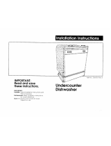
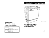
Installation Instructions
Built-In
Dishwashers
Models
ZBD5600
ZBD5700
ZBD5900

2
Before you begin - Read these instructions completely and carefully.
IMPORTANT - Save these instructions for local inspector’s use.
IMPORTANT - OBSERVE ALL GOVERNING CODES AND ORDINANCES.
Note to Installer - Be sure to leave these instructions with the Consumer.
Note to Consumer - Keep these instructions with your Use and Care Book for future
reference.
This appliance must be properly grounded. See “Power Supply”, page 8.
CAUTION
WARNING
If the dishwasher is a new installation, most of
the work must be done before the dishwasher
is moved into place. If this dishwasher is
replacing another dishwasher, the connections
must be checked for compatibility and re-
placed as necessary.
If you have a question concerning the installa-
tion of this product, call the GE Answer
Center
®
Consumer Information Service at
800.626.2000, 24 hours a day, 7 days a week.
If you received a damaged dishwasher, you
should immediately contact your dealer or
builder.
Contents
Design Information
Models Available............................................. 3
Product Dimensions....................................... 3
Advance Planning .......................................... 3
Standard Installation in 24" Deep Cabinets. 4
Optional Trim Kits ......................................... 4
Corner Installation......................................... 4
Installation Preparation
Parts Supplied................................................. 5
Materials You Will Need ................................ 6
Tools You Will Need....................................... 6
Prepare the Opening ..................................... 7
Water Supply................................................... 7
Power Supply .................................................. 8
Prepare Drain Plumbing ............................... 9
Installation of this dishwasher requires basic
mechanical and electrical skills. Proper
installation is the responsibility of the in-
staller. Product failure due to improper
installation is not covered under the GE
Appliance Warranty. See the Use & Care
Guide for warranty information.
CAUTION
• This dishwasher must be installed to allow
for future removal from the enclosure if
service is required.
• Use this appliance only for its intended
purpose.
For Monogram local service in your area,
1-800-444-1845.
For Monogram service in Canada,
1-888-880-3030.
For Monogram Parts and Accessories, call
1-800-626-2002.
Installation
Step 1 Remove Wood Base .......................... 10
Step 2 Install Leveling Legs
and Toekick Brackets ................................. 10
Step 3 Install Water Inlet Fittings................ 11
Step 4 Install Power Cord ............................ 11
Step 5 Level the Dishwasher........................ 12
Step 6 Slide Dishwasher into Opening....... 12
Step 7 Connect Water Line ......................... 12
Step 8 Install Drain Line.............................. 13
Step 9 Connect Electrical ............................ 13
Step 10 Secure Dishwasher to
Countertop or Cabinetry........................... 14
Step 11 Install Toekick Assembly ................ 15
Step 12 Install Side Filler Strips .................. 15
Panel Kits
ZPF25 Door Panel Kit .................................. 16
1/4" Thick Custom Door Panel
ZPF75 Door Panel Kit .................................. 19
3/4" Thick Custom Door Panel

3
Design Information
Stainless Steel Interior Dishwashers
Models
Available
ZBD5600 WW, ZBD5700WW
White Dishwashers
ZBD5600 BB, ZBD5700 BB
Black Dishwashers
ZBD5900
Stainless Steel Dishwasher
These dishwashers are designed for versatility,
adaptable to virtually any installation.
These models have a full length trimless door
without the traditional access panel. The
black and white models can be customized
with decorative panels of wood or other
material.
Product
Dimensions
A – 34” Min. adjustable
to 35” max.
B – 23-5/8”
C – 23-1/2” total depth
D – 4” max., 2-7/8” min.
E – 5” escutcheon height
F – Adjustable, to 3-1/4”
G – 25-1/4” from cabinets
face (depending on depth
of cabinets)
Advance
Planning
• The black and white models may be covered
with custom decorative door panels of wood
or other materials to match cabinetry. See
“Optional Trim Kits,” page 4.
• The stainless steel model does not accept
custom panels.
• A custom toekick can be installed to match
cabinet toekick material. A continuous
toekick may be installed to form an
unbroken line at floor level.
– A continuous toekick should be installed in
such a manner that it can be removed if
service is required.
• Tub flange trim is supplied to conceal any
slight gap between the dishwasher and
adjacent cabinetry.
• These dishwashers may be installed beneath
countertops of stone or other materials that
will not accept screws. No trim kit required.
See “Secure dishwasher to countertop or
adjacent cabinetry”, page 14.
G
C
B
E
A
D
F
Toekick

4
Design Information
Stainless Steel Interior Dishwashers
Standard
installation
in 24” deep
cabinets
• Install in standard 24” deep cabinets:
– The dishwasher door will be flush with the
front face of adjacent cabinetry.
• With a 3/4” thick custom door panel in
place, the exterior is trimless and fits flush
to adjacent cabinetry.
• ZPF25W, white or ZPF25B, black custom
panel kit – Provides for the installation of a
1/4” thick custom door panel. See page 16
for installation instructions.
• ZPF75W, white or ZPF75B, black custom
panel kit – Provides for a trimless appear-
ance using a 3/4” thick custom door panel.
See page 19 for installation instructions.
Optional
Trim Kits
• For a corner installation, allow 2” clearance
between dishwasher and adjacent cabinet
or wall.
• Dishwasher must be placed no more than
10 feet from sink for proper drainage.
Corner
installation
Cabinet
Depth
24"
Cabinet
Resting
Against Wall

5
Installation Information
Stainless Steel Interior Dishwashers
Parts
Supplied
Remove the hardware accessory bag and
other parts from inside or taped to the
outside of the dishwasher. Check contents
against drawings to insure that all parts are
included.
■■ Drain Hose hook
■■ 2 toekick slides
■■ 2 toekick brackets
■■ 2 side trim pieces
■■ 2-piece toekick
■■ 16 Screws (see illustration)
■■ 2 leveling legs
■■ Junction box
2 Leveling Legs
Drain Hose Hook
Screws A
(2) Countertop
Mounting
Screws B
(4) Side Trim
Screws C
(4) Toekick
Brackets
Screws D
(2) Countertop
Mounting
Left and Right Side
Toekick Brackets
2 Piece Toekick
Left and Right Side
Toekick Slides
2 Side Trim Pieces
Screws E
(2) Toekick
Slides-
Color Matched
Front Toekick Panel
Inner Toekick Panel
Junction Box
Screws F
(2) Junction Box

6
Installation Preparation
Stainless Steel Interior Dishwasher
Materials You
Will Need:
(not supplied)
■■ 90° elbow (3/8" NPT external thread on one end and opposite
end to fit hot water supply line)
■■ Thread seal tape
■■ UL listed wire nuts (3)
For new installations only:
■■ Air gap for drain hose, if required
■■ Waste tee for house plumbing, if applicable
■■ Electrical cable or power cord, if applicable
■■ Screw type hose clamps
■■ Strain relief for electrical connection
■■ Hand shut-off valve (recommended)
■■ Water line 3/8" O.D. min. copper or 1/2" O.D. min plastic.
■■ Phillips head and flat blade screwdrivers
■■ Adjustable wrench (6")
■■ 3/8", 5/16" and 1/4" nut drivers
■■ Level
■■ Carpenter’s square
■■ Measuring tape
■■ Safety glasses
■■ Flashlight
For new installation only:
■■ Tubing cutter
■■ Drill and appropriate bits
■■ Hole saw set
Tools you
Will Need:
(Not Supplied)
Electrical Cable
or Power Cord
90° Elbow
Screw Type Clamps
Thread Seal
Tape
Hot Water Line
Wire Nuts
Air
Gap
Strain Relief
Waste
Tee
Coupler
Flat Blade Screwdriver
Nut Driver
Hole
Saw Set
Level
Measuring Tape
Drill
and Bits
Adjustable
Wrench
Phillips Head
Screwdriver
Flashlight
Safety Glasses
Square
Shut-Off
Valve
Turbing
Cutter

7
Installation Preparation
Stainless Steel Interior Dishwasher
• The rough cabinet opening must be 24”
min. deep, 23-5/8” min. to 24” max. wide.
The opening height should be 34” min.
and 35” max.
• The opening should be free of extraneous
pipes and wires.
Prepare
the
Opening
Water
Supply
• Hot water line may enter from either side,
from the rear, or from the floor within the
shaded area shown.
• Turn off water supply.
• Cut a hole approximately 1-1/2” in diam-
eter to admit water line. Access hole must
be round and smooth.
• Install a hand shut-off valve in the supply
line in an accessible location, such as under
the sink. (The shut-off valve is optional, but
recommended and may be required by
local codes.)
• Install the hot water line, using no less than
3/8” O.D. copper tubing or 1/2” O.D.
plastic tubing.
• The water line must be long enough to
form a smooth natural loop with no sharp
bends or kinks between the cutout entry
and fill valve location, centered at the front
of the dishwasher.
• Adjust the water heater to deliver 120°F
min. water temperature.
• The water pressure of the hot water supply
line must be 20 to 120 psi.
• Before connecting, flush water line to clean
out debris.
34" to 35"
Underside
of Countertop
to Floor
This Wall Area
must be Free of
Pipes or Wires
23-5/8" Min.
24" Max
1-3/4"
24"
Min.
6"
6"
1-1/2"
Dia.
Hole
1-3/4"
2" from Floor
Cabinet Face
Hot
Shut-off Valve
Left
Side Entry
Approx. 30"
from Wall
Right Side Entry
Approx. 40"
from Wall

8
Installation Preparation
Stainless Steel Interior Dishwashers
Electrical Requirements:
These dishwashers must be supplied with a
120 volt, 60 Hz power supply with an indi-
vidual, properly grounded branch circuit,
protected by a 15 or 20 amp fuse or circuit
breaker or time delay fuse.
• Wiring must be 2 wire with ground.
• If electrical supply does not meet the above
requirements, call a licensed electrician
before proceeding.
Grounding Instructions:
This appliance must be either connected to a
grounded-metal permanent wiring system, or
an equipment-grounding conductor must be
run with the circuit conductors and be
connected to the equipment-grounding
terminal or lead on the appliance.
Power
Supply
FOR PERSONAL SAFETY:
REMOVE HOUSE FUSE OR OPEN CIRCUIT
BREAKER BEFORE BEGINNING
INSTALLATION.
DO NOT USE AN EXTENSION CORD OR ADAPTER PLUG WITH
THIS APPLIANCE. FOLLOW NATIONAL ELECTRICAL CODES OR
PREVAILING LOCAL CODES AND ORDINANCES.
Cabinet Preparation & Wiring:
• Wiring may enter from either side, the rear,
or from the floor within the shaded area
shown.
• Cut hole 1-1/2” max. diameter within the
shaded area to admit the electrical cable or
power cord. The hole must be free of sharp
edges. If the cabinet wall partition is metal,
the edge of the hole must be covered with a
rubber protector.
Electrical Connections:
The electrical connection is on the right side
of the dishwasher.
• For cable direct connections, the cable must
be routed as illustrated. The cable must
extend forward a minimum of 24” from the
rear wall.
• For power cord connections, install a
3-prong type receptacle in the rear wall of
sink cabinet next to the dishwasher. Install
the receptable at least 6” and not more than
18” from the dishwasher opening. The
receptacle should be at least 6” and not
more than 18” off the floor.
• Allow approximately 3” between cable and
adjacent cabinetry.
THE IMPROPER CONNECTION OF THE
EQUIPMENT - GROUNDING CONDUCTOR
CAN RESULT IN A RISK OF ELECTRIC SHOCK.
CHECK WITH A QUALIFIED ELECTRICIAN OR
SERVICE REPRESENTATIVE IF YOU ARE IN
DOUBT WHETHER THE APPLIANCE IS
PROPERLY GROUNDED.
White
18"
6"
24"
from Wall
3"
from
Cabinet
Alternate
Receptacle
Location
Ground
Black
1-1/2" Dia. Hole (Max.)
18"
6"
2"
Receptacle
Location
Area
2"

9
Installation Preparation
Stainless Steel Interior Dishwasher
Prepare
drain
plumbing
• Follow local codes and ordinances.
• Dishwasher drain hose must not exceed 10
feet in length for proper drainage.
– The dishwasher is supplied with a 3/4”
I.D. drain hose, 78” long. Add up to 42”
length to the factory supplied hose if
necessary.
• Dishwasher must be connected to waste line
with an air gap (not supplied) or 30”
minimum, high drain loop (depending on
local codes and ordinances) to prevent
back flow into the dishwasher.
• An air gap must be used if waste tee or
disposer connection is less than 12” above
floor to prevent siphoning.
• Install waste tee or disposer and air gap
according to the manufacturer’s instruc-
tions.
• Cut a hole in cabinet wall, approximately
1-1/2” in diameter for drain hose.
• Install drain hose hook to underside of
countertop.
Method 1 – Air Gap with Waste Tee or Disposer
Use this method when waste tee or disposer connection is less
than 12” above the floor.
An air gap MUST BE USED if the drain
hose is connected to waste tee or disposer
lower than 12” above the floor level.
Failure to provide the proper drain con-
nection height, 12", with air gap or 30”
minimum high drain loop will result in
improper draining of the dishwasher which
may cause damage.
12"
Min.
30"
Min.
18"
Min.
30"
Min.
Waste Tee Installation Disposer Installation
Waste Tee Installation Disposer Installation
Method 2 – High Drain Loop
with Waste Tee or Disposer
Use this method when high drain loop is at least 30” above the
floor.
CAUTION

10
Installation
Stainless Steel Interior Dishwasher
Install Custom
Door Panel
• If you intend to install custom door panels,
refer to installation instructions provided in
this booklet. The panels should be in place
before installing the dishwasher.
Step 1
Remove
wood base
Step 2
Install
leveling legs
& toekick
brackets
• Un-wrap the drain hose and pull to the rear
of the dishwasher. Take care not to kink or
crush the hose.
• Install toekick support brackets on the left
and right sides of the mounting brackets
using 2 screws each. Toekick brackets are
designed to fit either left or right sides. See
illustration for correct orientation.
• Install the front leveling legs provided in
the parts package. The legs should be at
least 2” from the bottom edge of the
mounting bracket.
• Adjust leveling legs to installation height.
Cut the shipping carton and use it as a pad
under the dishwasher. This will protect the
finished floor in the kitchen.
• Lay the dishwasher on its back.
• Remove the 4 screws holding the dish-
washer to the wood base. Discard screws.
• Retain wood base.
• Insure that the floor of the cutout is the
same level or higher than the rest of the
room. If the kitchen floor is tile, it may be
elevated above the floor of the installation
cutout. Pieces of the wood base may be
placed into the cutout floor to make it level
or higher than with the kitchen floor. This
will allow for easy removal for any future
service.
22-7/16"
2" Min.
Mounting Bracket
Toekick Support Bracket
Screws C

11
Installation
Stainless Steel Interior Dishwasher
Step 3
Install
Water Inlet
Fittings
Step 4
Install
power cord
(If used)
Skip this step
If dishwasher
will be wired
direct.
• Install the 90° elbow onto the water inlet.
Use thread sealing tape or pipe thread
compound.
• The 90° elbow should face the left or right
side, depending on water line routing.
• Install strain relief onto junction box and
tighten against incoming wires.
• Strip 1/2” insulation from end of power
cord wires.
• Connect incoming wires to dishwasher wires
using wire nuts of appropriate size.
• Connect the white to white, black to black
and incoming ground to green wire.
• Push all wires into the junction box and
secure cover with screws onto dishwasher
frame.
Note: The power cord and connections must
comply with the National Electrical Code,
Section 422 and/or local codes and
ordinances.
IMPORTANT: The power cord must be no
longer than 6 ft from the junction box to the
plug. DO NOT PLUG IN POWER CORD AT
THIS TIME.
Screws F

12
Installation
Stainless Steel Interior Dishwasher
Step 5
Level the
Dishwasher
Step 6
Slide
Dishwasher
Into Opening
• Carefully upright the dishwasher, taking
care not to bend the leveling legs.
• Check to be sure the dishwasher is level and
at the cutout height.
• Insert drain hose into the hole previously
drilled in the cabinet wall.
• Slide the dishwasher into the opening a few
inches at a time.
• As you proceed, pull the drain hose
through the cabinet wall under the sink.
• If a power cord is used, guide the end
through a separate hole.
• Check to be sure there is no interference
with waterline or house wiring.
Step 7
Connect
Water Line
• The water supply line should be flushed to
clear any foreign material before connect-
ing to the dishwasher.
• Make sure there are no sharp bends or
kinks which could restrict the water flow.

13
Installation
Stainless Steel Interior Dishwasher
• Follow all local codes and ordinances.
Drain Line Preparation
• The dishwasher is supplied with a 78” long
corrugated drain hose.
• If the location requires a longer drain hose,
add up to 42” length to the supplied hose.
Use 3/4” inside diameter hose and thin
wall copper coupler to join the hose ends.
Note:
Total drain hose length must not exceed 10 feet for
proper drain operation.
Drain Line Installation
• Connect drain line to air gap, waste tee or
disposer using either method 1 or 2 as
previously determined.
• Secure connection using appropriate
clamps (not supplied).
• Make sure drain hose is not kinked.
Note:
Remove drain plug before connecting to disposer.
Dishwasher cannot drain if plug is left in place.
Step 8
Install
Drain Line
Step 9
Connect
Electrical
(For direct
connection to
house wiring)
Verify that power is turned off at the source.
• Install a strain relief onto the junction box
and tighten against the incoming wires.
• Strip 1/2” insulation from end of incoming
wires.
• Connect white to white, black to black and
incoming ground to green wire.
• Push all wires into the junction box and
place on dishwasher frame. Secure with
screws “F”.
Waste Tee Installation Disposer Installation
Waste Tee Installation Disposer Installation
Method 1 – Air Gap with Waste Tee or Disposer
Method 2 – High Drain Loop
with Waste Tee or Disposer
Fasten to underside
of countertop
30"
Min.
12"
Min.
12"
Min.
Fasten to underside
of countertop
30"
Min.
If house wiring is not 2-wire with a ground wire,
a ground must be provided by the installer.
When house wiring is aluminum, be sure to use
U.L. listed anti-oxidant compound and
aluminum-to-copper connectors.
Screws F

14
Installation
Stainless Steel Interior Dishwasher
Step 10
Secure
Dishwasher
to Countertop
or Cabinetry
To maintain position and alignment the
dishwasher must be secured to the countertop
or to adjacent cabinetry.
If countertop is of stone or other hard
material, secure the dishwasher to adjacent
cabinets.
• Check to be sure that dishwasher is adjusted
to correct height and is centered in the
cutout.
• Open and close dishwasher door to insure
proper operation of the door. If there is any
binding or rubbing, readjust leveling legs.
Secure dishwasher to countertop:
• Drill pilot holes through the mounting
bracket and into the underside of the
countertop. Install 2 screws “A” provided.
Secure dishwasher to adjacent cabinets:
• Remove plastic plug button on the inside of
the dishwasher frame. One on each side.
• Drill pilot holes through the holes and into
the adjacent cabinets. Install 2 screws “D”
provided.
Screws A
Screws D

15
Installation
Stainless Steel Interior Dishwasher
• Install toekick slides to toekick support
brackets. Use slide stamped “L” on left and
“R” on right side.
• Align front and inner toekicks, matching
screw holes.
• Align slides to second screw hole as illus-
trated.
• Install color matched screws “E” through
the front of the toekick and into the toekick
slides. Do not tighten screws.
• Carefully, slide assembly back until it is
aligned with adjacent cabinetry toekick.
• Adjust the height of the panel by loosening
screws and sliding the front panel down,
even with the floor.
• Carefully, hold the door and open fully.
Insure that door does not strike top of
toekick.
• Adjust toekick height if necessary.
• Tighten screws.
Step 11
Install
Toekick
Assembly
Step 12
Install
Side Filler
Strips
• Side filler strips are packed with this dish-
washer. If the cabinet cutout is wider than
the dishwasher, install the filler strips on
both sides of the dishwasher to cover gaps.
• Open the door fully.
• Place side trim against dishwasher tub and
install 2 screws, loosely on each side.
• Adjust trim to correct width. Tighten screws.
Attachment Screws
Slide toekick out
Pull tab while
Pushing toekick in
Screws E
Screws B
Front Toekick Panel
Inner Toekick
Left Side
Toekick
Slide
Side
Trim

16
ZPF25 Custom Door Panel Kit
1/4" Thick Custom Door Panel
• Cut door panel to the dimensions shown.
• The bottom left and right corners should
be cut at 1/4” radius. See illustration.
Note: The trim will conceal the cut edges of the panels.
To prevent electrical shock,
disconnect electrical power
supply to dishwasher before
changing panels. Do not
operate dishwasher when
door assembly is removed.
ZPF25B, Black trim
ZPF25W, White trim
Tools and Materials required
• Phillips screwdriver
• Gloves to protect against sharp edges.
Step 1
Cut 1/4”
Thick Custom
Panel to Size
1/4" Thick
Door Panel
25-1/2"
23-1/8"
1/4"
Radius
Cut
Note:
It is best that 2 people perform this installation.
The ZPF25 trim kit provides support for 1/4”
thick custom door panel.
Note:
Maximum custom panel weight is
10 pounds.
• Metal door
• 10 wood screws
• 6 “C” clips
• Door Trim
• 2 Door Springs
Kit Contents
Screws
Metal Door
Door Trim
2 Door
Springs
“C” Clips

17
ZPF25 Custom Door Panel Kit
1/4" Thick Custom Door Panel
• Place the supplied metal door on a flat
surface.
• Place the custom panel on top of the metal
door.
• Place supplied trim over the custom panel.
• Press trim to panel and install the color
matched screws provided. Install 3 screws
on each side and 2 screws on the bottom.
Step 3
Assemble
Panel to
Door
• Turn the assembled door over with appear-
ance side down.
• Install center door bracket onto door using
original screws.
• Place insulation around support bracket.
Step 4
Install Door
Center
Bracket
Step 2
Remove
Existing
Metal Door
• Open the door fully.
Caution: One person should hold the door
while the other backs out screws to prevent
the metal door from falling.
• Remove 6 screws on the inside the inner
door frame. Retain screws.
• Remove the 2 screws with o-rings located in
the bottom center of the inner door. Retain
screws and o-rings.
• Remove the outer door.
• Remove the 2 screws holding the center
door bracket to metal door.
• Retain bracket, and insulation.
• Discard metal door.
Door Trim
Door Panel
Decorative Panel
Insulation
Install Screws

18
ZPF25 Custom Door Panel Kit
1/4" Thick Custom Door Panel
The additional weight of the custom panel
may require that the heavy door springs be
installed.
Test Door Balance
• With one hand under the door, slowly open
the door fully.
• Open and close the door to check for
proper balance. Correct door balance
should prevent the door from raising by
itself from a full open position and prevent
the door from falling heavily.
• If the door falls heavily, damage will occur
from repeated use.
• Install one or both new springs provided.
Install New Springs:
• Close and latch the dishwasher door.
• Locate door spring on left side of dish-
washer.
• Disengage the push rod guide by pushing
down on the guide and slowly pulling the
guide out of the mounting position.
• Carefully release the tension on the spring
and remove the push rod guide from the
rod.
• Remove the spring and replace with the
spring that has a yellow marking.
• Reassemble the push rod guide into the
original position.
• Test door balance.
• Install right side spring if needed.
Step 5
Install
Assembled
Door onto
Dishwasher
Step 6
Install
Door
Springs
• Locate the “C” clips in the parts package.
Place one clip, flat side up, over each of the
screw holes, 3 on each side of the door.
Note:
One person should hold the door while the other installs
screws to prevent the door assembly from falling.
• Hold the assembled door to dishwasher
inner door and slide up against control
panel. Control panel has posts that should
engage the 2 holes in the top of the metal
door.
• Install the original center screws and
o-rings.
Note:
Center screws and o-rings must be securely fastened to
prevent future leaks.
• Install original screws to sides of inner door
frame, 3 each side.
Push
Rod
Guide
“C” Clips

19
ZPF75 Custom Panel Kit
3/4" Thick Custom Door Panel
To prevent electrical shock,
disconnect electrical power
supply to dishwasher before
changing panels. Do not
operate dishwasher when
door assembly is removed.
ZPF75B, Black
ZPF75W, White
Tools and Materials required
• Phillips screwdriver
• Gloves to protect against sharp edges
• Nut driver
Step 1:
Determine
Custom
Panel
Sizes
The custom panel should be constructed in
the same manner as cabinet doors. All edges
can be seen and must be finished for the best
appearance.
Note:
It is best that 2 people perform this installation.
The ZPF75 provides for the installation of
1/2” to 3/4” thick custom door panel.
Note:
Maximum custom panel weight is
10 pounds.
• Metal door
• Support bracket
• Label
• 18 Screws
Kit Contents
Screws X
(10) Wood Screws
Screws Y
(6) Not Used
Screws Z
(2) Support Bracket
Door Springs
Metal Door
Support
Bracket
Dim. A*
*Height
23-1/8"
Custom
Panel Size
Floor
Cabinets
Countertop
Top
3/4" Max.
3/4" Thick
Door Panel
Bottom of
Adjacent Cabinetry
*Height is equal to A minus 5-1/8" plus 1/4"
EXAMPLE:
A = 30-1/2" minus 5-1/8", plus 1/4" is equal to 25-5/8".
• Measure dimension A, from underside of
countertop to bottom of adjacent cabinets.
– Subtract 5-1/8". Control panel height is 5".
Allow 1/8" for gap between bottom of
countertop and top of control panel.
– Add 1/4". The custom panel will slide up,
behind control panel.

20
ZPF75 Custom Panel Kit
3/4" Thick Custom Door Panel
Step 2
Remove
Existing
Metal Door
• Open the door fully.
Caution:
One person should hold the door while the other
backs out screws to prevent the metal door from falling.
• Remove 6 screws on the inside of the
frame. Retain screws.
• Remove the 2 screws with o-rings located in
the bottom center of the door. Retain
screws and o-rings.
• Remove the door.
• Remove insulation and foam inserts,
discard metal door.
Step 3
Install Door
Center Bracket
• Install new center door bracket onto door
using screws “Z”.
• Place insulation around support bracket.
Step 4
Assemble
Custom
Panel
• Lay custom panel on a flat surface, appear-
ance side down.
• Place the new metal door panel onto the
back of the custom door panel. Align sides
and top edges.
• Drill 1/8” pilot holes, 3/8” deep, through
the metal panel and into the custom panel,
3 each side.
• Secure custom panel to metal door with 3
screws “X” on each side.
• Drill 1/4” pilot holes through the top
return flange, approximately 1/4” deep.
2 “O” Rings
2 Foam
Inserts
Metal Integrated Door
Flat Face
Support Bracket
2- Depressions
Screws X
Screws Z
Drill 1/4"
Holes
Custom Panel
Drill 1/8" Holes
(3 Each Side)
Page is loading ...
Page is loading ...
Page is loading ...
Page is loading ...
/