MIMAKI CJV300 Plus User guide

Type
User guide

This manual is also suitable for

UCJV300/150, CJV300 Plus series
ID Cut Guide
Congratulations on your purchase of an inkjet printer of MIMAKI (print & cut type).UCJV300/150, CJV300 Plus
series This " ID Cut Guide", describes the method for ID cut by using UCJV300/150, CJV300 Plus series and the
supplied software. Precautions and predefined settings are also described.
Note
It is strictly prohibited to write or copy a part or whole of this document without our approval.
This document has been carefully prepared for your easy understanding, however, please do not hesitate to
contact a distributor in your district or our office if you have any inquiry.
Description contained in this document are subject to change without notice for improvement.
Due to improvement or change of software, the description of this document could be partially different in
specification, for which your understanding is requested.
With the exception of what is provided for in the warranty provisions of MIMAKI ENGINEERING CO., LTD., we
do not assume any liability against the damages (including but not limited to the loss of profit, indirect damage,
special damage or other monetary damages) arisen out of the use or failure to use of this product. The same
shall also apply to the case even if MIMAKI ENGINEERING CO., LTD. had been notified of the possibility of
arising damages in advance. As an example, we shall not be liable for any loss of the media made using this
product or indirect damages caused by the product made using this media.
You can also download the latest operation manual from our website.
FineCut, RasterLink, RasterLink6Plus and CuttingLink are registered trademarks of MIMAKI ENGINEERING CO.,
LTD.
Adobe Illustrator is a trademark of Adobe Systems Incorporated.
CorelDRAW is a trademark of Corel Corporation.
Microsoft and Windows are registered trademarks of Microsoft Corporation of the U.S.A.
Apple and Macintosh are registered trademarks of Apple Inc. of the U.S.A. and each country.
All brand names and product names are trademarks or registered trademarks of their respective companies.
- 2 -
Note ............................................................................................................ 1
What is ID cut? .......................................................................................... 3
ID Cut Procedure ....................................................................................... 4
Preparation ................................................................................................................................... 5
Set up PC. .................................................................................................................................. 5
Printing, and ID Cutting ................................................................................................................. 8
Set the media. ............................................................................................................................ 8
Print data. ................................................................................................................................... 9
ID cut ........................................................................................................................................ 11
How to handle the following cases........................................................ 12
Troubleshooting .......................................................................................................................... 12
Changed CuttingLink - Server. ................................................................................................... 14
Back up the data of CuttingLink - Server. ................................................................................... 14
Migrate CuttingLink - Server. ...................................................................................................... 14
1. Reset initial setting on CuttingLink - Server PC before migration. ....................................... 14
2. Configure Server on CuttingLink - Server PC to be migrated. ............................................. 14
3. Register CuttingLink - Server PC on RasterLink6Plus. ........................................................ 14
When to use CuttingLink - Client? .............................................................................................. 15
How to set CuttingLink - Client ................................................................................................. 15
Data in the same place is cut twice ............................................................................................ 16
When you want to ID cut multiple types of data .......................................................................... 17
TABLE OF CONTENTS
- 3 -
What is ID cut?
It is a function that can cut automatically according to the ID information simply by detecting the ID-contained
data. You do not have to output the cut data again after printing the data. (Typically, you need to print the print
data and the cut data separately.)
ID Cut Operation Flow
System configuration
ID Data Print
ID Data
Adjusting the image quality
and colors, and so on.
register marks
detection.
Automatically cut
Cut Data
(Auto)
Printed
Cut Data
(Auto)
Cut data management.
UCJV300/150, CJV300
Plus series
1-4.Regitration of CuttingLink(P. 6)
1-3.Regitration of UCJV300/
150, CJV300 Plus series(P. 5)
USB
or
Ethernet
UCJV300/150, CJV300
Plus series
- 4 -
ID Cut Procedure
1. Software / Driver List (P.5)
2. Set the media. (P.8)
3. Print data. (P.9)
4. ID cut (P.11)
1. Connect PC and UCJV300/150, CJV300 Plus series with USB or Ethernet.
(P.5)
2. Install CuttingLink. (P.5)
3. Register UCJV300/150, CJV300 Plus series with CuttingLink. (P.5)
4. Register CuttingLink with RasterLink6Plus. (P.6)
1. Set the media onto UCJV300/150, CJV300 Plus series. (P.8)
2. Check if the media margin is sufficient.(P. 8)
1. Start RasterLink6Plus. (P.9)
2. Read the Sample file. (P.9)
3. Add register marks and ID data. (P.9)
4. Select [RIP & Print] or [Immediate Print]. (P.10)
5. Click [Start]. (P.10)
6. Data with ID will be printed. (P.10)
1. Detect the register mark (P.11)
2. The cut data is automatically received and cut. (P.11)
- 5 -
Preparation
You need to prepare UCJV300/150, CJV300 Plus series and the software/Driver before printing or ID cut.
If preparations have already been completed, go to"Printing, and ID Cutting" (P.8).
Software / Driver List
The following software applications are required for ID cut. All software applications are provided by MIMAKI
ENGINEERING CO., LTD.
Set up PC.
1. Connect PC and UCJV300/150, CJV300 Plus series with USB or Ethernet.
2. Install the software/driver.
(1) Install Mimaki Driver.
(2) Install RasterLink6Plus.
(3) Install CuttingLink.
3. Register UCJV300/150, CJV300 Plus series with CuttingLink.
(1) Start CuttingLink from the start menu, or double-click
the CuttingLink icon created on the desktop to start
CuttingLink.
The [Initial Setting] screen is displayed.
Software/Driver Description
RasterLink6Plus
*1
Ver.2.3 or later
*1.When using a version earlier than the specified version, download the upgraded version of the installer
from the Mimaki website.(http://mimaki.com/
)
Software to receive image data, edit data with various functions, and
send plot data to the printer. (supplied with the printer: CD)
Refer to the attached RasterLink6Plus Installation Guide for the
installation method.
CuttingLink
*1
Ver.1.1.4 or later
Software to manage ID cut.
Download the installer from the Mimaki website(http://mimaki.com/
)
Refer to the attached "CuttingLink installation" of Raster-
Link6Plus Installation Guide for the installation method.
Mimaki Driver
Device driver for using an ink jet printer/cutting plotter from Mimaki
Engineering. (supplied with the printer: CD)
Refer to the attached Mimaki Driver Installation Guide for the
installation method.
- 6 -
(2) On the [Initial Setting] screen, select [CuttingLink-Server],
and then click [OK].
[Data Management] is displayed.
(3) From the [Tool] menu, select [Cutting Device Manager].
(4) Select UCJV300/150, CJV300 Plus series in [Available
Devices].
(5) Enter [Name], and then click [Add].
UCJV300/150, CJV300 Plus series is added to the list.
(6) Click [Close].
4. Register CuttingLink with RasterLink6Plus.
Make sure that CuttingLink is running.
(1) Start RasterLink6Plus.
CuttingLink is started automatically when PC starts.
- 7 -
(2) Select [Option...] from the [Environments] menu in Raster-
Link6Plus.
(3) Click the [Communication] tab on the [Option] screen.
(4) [Setting of ID Cut: Click [Setup] in [Connection destination].
The [Connection destination setting] screen is displayed.
(5) On the [Connection destination setting] screen, select this
my computer, and then click [OK].
The [Connection destination setting] screen is closed.
On the [Option] screen, "PC name (IP address)" is dis-
played in [Connection destination].
(6) Click [OK] on the [Option] screen.
Connects with CuttingLink.
- 8 -
Printing, and ID Cutting
The following shows you how to use and print out the sample data from the attached manual CD.
If there is no sample data, create data including illustrations and cut lines.
Set the media.
For detail, refer to the UCJV300/150, CJV300 Plus series Operation Manual.
I you cut the media rotated by 90, 180, or 270 degrees, set the media margins to the following values at
rotated conditions.
Front end: 110 mm or more
Left and right ends: 15 mm or more
Rear end: 110 mm or more
210 mm or more (When copying data with RasterLink6Plus.)
1. Set the media onto UCJV300/150, CJV300 Plus series.
2. Check if the print start position (the origin ) is set at 110 mm or more from the media
front end, and 15 mm or more from the media right end.
Make sure that the width of the media is equal to or larger than [Entire image width (including the reg-
ister mark) + right 15 mm + left 15 mm].
If any of the front / left / right margin is insufficient, the media end may be mistaken as the register
mark, which may cause the register mark detection to start earlier.
(1) Press the jog key in the local state. Move the luminous point of the LED pointer so that the print
start position is 110 mm or more from the media front end, and 15 mm or more from the right end.
(2) Press the [ENTER] key.
The print start position is changed.
3. Check if the print end position is set at 110 mm or 210 mm (When copying data with
RasterLink6Plus.) from the media rear end.
Make sure that the length of the media is equal to or larger than [Entire image length (including
the register mark) + 110 mm + 110 mm or 210 mm(When copying data with RasterLink6Plus.)].
Make sure that you check P.5 "Preparation" and then print and cut.
Range to place
designe
Effective cut range
110 or 210 mm or
more
70 to 3000 mm
70 mm or more
Range to place
design
Effective cut range
110 mm or 210 mm +
(half the length of the
register mark) or more
70 to 3000 mm
70 mm or more
110 mm + (half the
length of the register
mark) or more
[Mark Shape: Type 1] [Mark Shape: Type 2]
Front
Rear
110 mm or more
15 mm or more15 mm or more 15 mm or more15 mm or more
- 9 -
Print data.
1. Start RasterLink6Plus.
2. Set the manual CD to your computer.
If there is no sample file, create the sample file with the following procedure and go to step 3.
(1) Create "illustration data" and "cut line data".
(2) Placing the "illustration data" on the print layer ([Print] attribute: ON) and the "cut line data" on the
cut layer ([Print] attribute: OFF).
3. From the [File] menu, select [Open].
The [Select file name to print] screen is displayed.
4. Read the Sample file.
If there is no sample file, use the data created in step 2.
(1) Select the following files on the [Select file name to print]
screen, and click [Open].
For Windows: "CD drive:\EN\English\
ID Cut_Sample data\sample_mimaki.eps"
For Macintosh: “CD drive:\Mac_English\
ID Cut_sample data\sample_mimaki.eps”
(2) The sample data is loaded.
Sample data is created with RasterLinkTools.
For details on how to create print & cut data, refer to the
RasterLink 6Plus Reference guide "RasterLinkTools".
5. Select the read data and click the [General Print] icon in the function icon list on
the right side of the screen.
6. Add register marks and ID data.
The conditions under which ID cut is possible are as follows.
Mark Shape: [Type 1 ] or [Type 2 ]
Size of data: more than 70 mm in length and width
(1) Set the number of copies.
(2) Select a register mark shape.
- 10 -
(3) Check [ID Cut].
Register marks and ID data are added to the data.
7. Click the Execution icon in the function icon list on the right side of the screen.
8. Select [RIP & Print] or [Immediate Print].
9. Click [Start].
10. Data with ID will be printed.
ID data
- 11 -
ID cut
1. Detect the register mark
(1) Press the [SEL] key twice in LOCAL mode.
(2) Press [][] key to select [MARK DETECTION], and press the [ENTER] key.
This switches to the mark detection mode.
(3) Press the [][][][]keys to move the luminous point of the LED pointer to the center of the reg-
ister mark.
(4) Press the [ENTER] key.
The register mark is detected.
The printer is in remote mode.
2. The cut data is automatically received and cut.
Mark Shape: Type 1
Mark Shape: Type 2
- 12 -
How to handle the following cases.
Troubleshooting
The [ID Cut] check box is disabled in
RasterLink6Plus.
Is the data size of the job 70 mm or more? Set the data size to 70 mm or more.
Have you selected [Type 1], [Type 2] for
the register mark shape?
Select [Type 1] or [Type 2] for register mark
shape.
Contact the call center.
In the message display field of RasterLink6Plus, error
message,"Can not get ID cut ID, printing is
interrupted" is displayed and printing is not possible.
Is it connected to the CuttingLink - Server
PC via Ethernet?
If CuttingLink and RasterLink6Plus are
installed on the same PC, proceed to
"Yes".
Connect with Ethernet.
( P.6 "Register CuttingLink with Raster-
Link6Plus.")
Is CuttingLink started with CuttingLink? Start CuttingLink with CuttingLink.
Is CuttingLink - Server PC properly regis-
tered with RasterLink6Plus?
Confirm the following contents.
On the RasterLink6Plus [Environments]
menu - [Option ...] - [Communication] tab,
is the CuttingLink - Server name displayed
in "Setting of ID Cut" - "Connection desti-
nation"?
Register CuttingLink - Server PC name
again.
( P.6 "Register CuttingLink with Raster-
Link6Plus.")
Connected to the CuttingLink - Server PC
you registered?
Check with the following procedure.
(1) On the RasterLink6Plus [Environ-
ments] menu - [Option ...] - [Communi-
cation] tab, click [Setting] of "Setting of
ID Cut" - "Connection destination"?
(2) On the [Connection destination set-
ting.] screen, click the [Update].
(3) Is the registered CuttingLink - Server
PC name displayed?
Register CuttingLink - Server PC name
again?
If the address of the CuttingLink - Server
PC has been changed, re-registration is
necessary.
( P.6 "Register CuttingLink with Raster-
Link6Plus.")
Contact the call center.
No
Yes
No
Yes
No
Yes
No
Yes
No
Yes
No
Yes
- 13 -
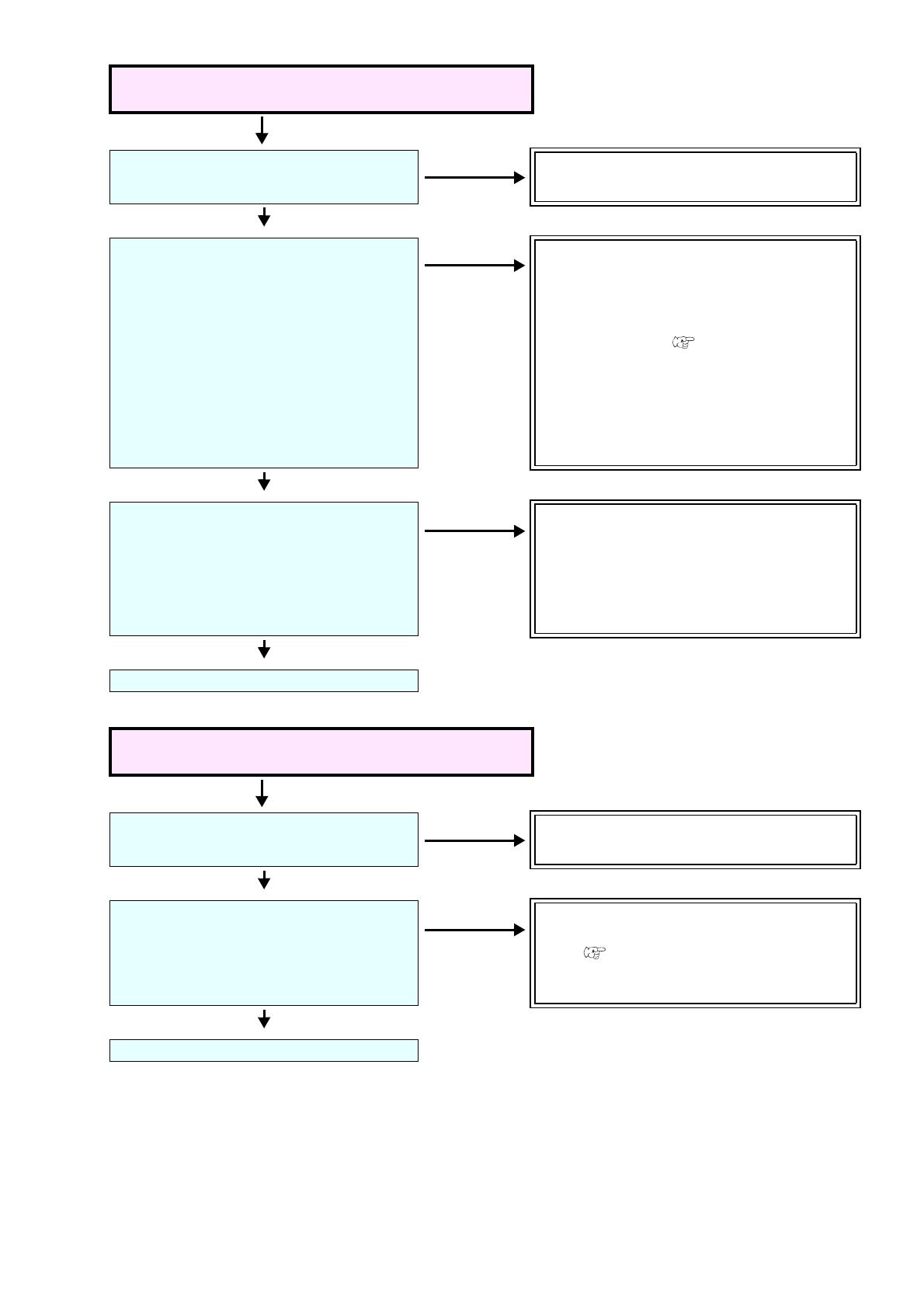
Even if register marks are detected with UCJV300/
150, CJV300 Plus series, ID cut is not performed.
Is PC and UCJV300/150, CJV300 Plus
series connected via USB or Ethernet?
Connect with USB or Ethernet.
Is UCJV300/150, CJV300 Plus series
properly registered in CuttingLink -
Server?
Confirm the following contents on the
[Cutting Device Manager] tab of Cuttin-
gLink - Server.
(1) Is [Output Port] the same as what is
physically connected? (USB/Ethernet)
(2) Is the serial number displayed in
[Device Name] the same as the serial
number of the UCJV300/150, CJV300
Plus series main unit?
Register UCJV300/150, CJV300 Plus series
with Cutting -Link.( P.5 "Register
UCJV300/150, CJV300 Plus series with Cut-
tingLink.")
Is the ID cut setting correct in UCJV300/
150, CJV300 Plus series?
Check the following contents on the oper-
ation panel.
Is [CUTTING] - [MARK DETECTION] -
[FORM] and [SIZE] the same as the print
register mark data?
Set the same register mark shape and size
as the print register mark data with
UCJV300/150, CJV300 Plus series.
Contact the call center.
When multiple register marks with different IDs are
attached, does not cut continuously.
Is the shape and size of the register mark
printed all the same?
Make all shapes and sizes of register marks
same.
Are the values for [CUTTING] - [MARK
DETECTION] - [DETECT AREA] appropri-
ate on UCJV300/150, CJV300 Plus
series?
Enter the correct set [cutting] - [register mark
detection] - [detection area] with UCJV 300/
150. ( P.19 "Set the register mark detec-
tion area on the operation panel of
UCJV300/150, CJV300 Plus series.")
Contact the call center.
No
Yes
No
Yes
No
Yes
No
Yes
No
Yes
- 14 -
Changed CuttingLink - Server.
Register CuttingLink again with RasterLink6Plus.
( P.6 "Register CuttingLink with RasterLink6Plus.")
Back up the data of CuttingLink - Server.
Back up the following folders.
C:\MimakiTools\CuttingLink\DT
Migrate CuttingLink - Server.
1. Reset initial setting on CuttingLink - Server PC before migration.
1. Back up CuttingLink - Server data.
( P.14 "Back up the data of CuttingLink - Server.")
2. From the [Tool] menu, select [Initial Settings Reset]
and click the [OK] button.
3. Exit CuttingLink.
2. Configure Server on CuttingLink - Server PC to be migrated.
1. Install and start CuttingLink.
After restarting the PC after installation, CuttingLink will be started automatically.
2. On the [Initial Setting] screen, select [CuttingLink -
Server], and then click [OK].
3. Exit CuttingLink.
4. Copy the data backed up on the PC before migration to the folders below.
C:\MimakiTools\CuttingLink\DT
5. Start CuttingLink.
6. Register the UCJV300/150, CJV300 Plus series.
( P.5 "Register UCJV300/150, CJV300 Plus series with CuttingLink."(3) to (6))
3. Register CuttingLink - Server PC on RasterLink6Plus.
P.6 "Register CuttingLink with RasterLink6Plus."
- 15 -
When to use CuttingLink - Client?
CuttingLink - Server can register up to five plotters. As shown below, use Cutting - Client to connect more than 6
plotters.
How to set CuttingLink - Client
1. Install CuttingLink on the PC connecting 1st to 5th UCJV300/150, CJV300 Plus
series, and set it to CuttingLink - Server.( P.5 "Install CuttingLink." or later)
2. Install CuttingLink on the PC connecting the sixth UCJV300/150, CJV300 Plus series
and set it to CuttingLink - Client.
(1) Install CuttingLink on the PC to which the plotter is connected and start it.
(2) On the [Initial Setting] screen, select [CuttingLink -
Client], and then click [OK].
Printer - Server PC1
Printer - Server PC2
Register
Register
Register
Reg
ister
- 16 -
(3) In the [Connection destination settings] list, select the
CuttingLink - Server to connect and click [OK].
Make sure that CuttingLink - Server is running with Cuttin-
gLink - Server PC.
If the [Connection destination settings] screen does not
appear, select the [Connection destination settings] on the
[Tool] menu.
If the PC is not displayed, click[Update].
Data in the same place is cut twice
For data of Adobe Illustrator 9 or later to which a transparent effect has been applied, when Print & Cut is
executed in RasterLink6Plus, cut data may be cut twice.
In such a case, change the settings as follows by using Adobe Illustrator.
(1) Separate the “Print data” and the “Cut data”, and then move the “Cut data” layer on top.
(2) From the [File] menu, select [Document Setup...].
(3) On the [Document Setup] dialog, click ”Preset” on the right of [Custum...].
(4)
On the [Custom Transparency Flattener Options] dialog,
"Convert All Text to Outlines" and set “Con-
vert All Strokes to Outlines” to OFF.
- 17 -
When you want to ID cut multiple types of data
If you print multiple register marks and perform ID Cut, set the same shape and size for all the register
marks. If any of the register marks has a different size or shape, the ID Cut is canceled.
1. Read print & cut data with RasterLink6Plus.
Data size should be more than 70 mm in length and width.
Create print & cut data in the following way.
Create print data and cut data with Adobe Illustrator / Corel DRAW, and output ID cut without creating
and recognizing register marks with FineCut. (Data will be sent automatically to RasterLink6Plus.)
2. Select the data read with RasterLink6Plus and click the [General Print] icon in the
function icon list on the right of the screen.
3. Set printing conditions.
(1) Set [Scale].(Arbitrary)
Scale can not be set for data with ID sent from FineCut.
(2) [Rotation] and [Mirror] are set.(Arbitrary)
(3) Set [Scan] and [Feed] of [Position].(Arbitrary)
It is unnecessary to set when setting a margin of 10 mm
or more.
If not, enter "10 mm" or more in [Scan] and [Feed].
(4) Enter [Copy] number.
(5) Set [Space] or [Pitch] of [Layout].
When adding register marks, the following values are
automatically set for [Space].
When the register mark shape is [Type1 ]: Register
mark size
When the register mark shape is [Type2 ] 0mm
Because the shape of the register mark is different, an
error occurs and the ID Cut is canceled.
Mark Shape: Type1
Mark Shape: Type1
Cutting direction
Mark Shape: Type2
(1)
(2)
(3)
(4)
(5)
- 18 -
4. Add register marks and ID data.
(1) Select the register mark size.
[Type1 ], [Type2 ]
(2) Enter the register mark size.
(3) Check [ID Cut].
Register marks and ID data are added to the data.
For ID Cut data sent from FineCut, the [ID Cut] check box is already checked. You can not
uncheck it.
(4) Select [Location] of register mark.
Individual: Register marks and ID data are added for each data.
Whole: Register marks and ID data are added to enclose all copied data.
(5) [Offset] is set when [Whole] is selected in (4).
Offset: Data and margin of register mark
5. Output data with RasterLink6Plus( P.9 "Print data.")
Data with ID will be printed.
6. Create another data and repeat Step1 to Step5.
7. Set the printed media on UCJV300/150, CJV300 Plus series.
(5)
Offset
Offset
OffsetOffset
- 19 -
8. Set the register mark detection area on the operation panel of UCJV300/150, CJV300
Plus series.
(1) Press the [MENU]([FUNC1] key) in LOCAL mode.
(2) Press [][] key to select [CUTTING], and press the [ENTER] key.
(3) Select [MARK DETECTION], and press the [ENTER] key.
(4) Press the [FUNC3] key.
(5) Press the [][] key to set the following items, and press the [ENTER] key.
SCAN DIRECTION, FEED DIRECTION, and OFFSET X of [DETECT AREA] are as follows.
Item Value Set value
DETECT AREA -
You can configure various settings for the register mark
operation.
SCAN DIR.
DEFAULT,
0 cm,
5 cm to the
machine width
Configure the detection width for the scanning direction. The
register mark is detected while scanning is performed bidi-
rectionally at the set detection width.
• DEFAULT: The register mark is detected at half the media width.
• 0 cm: The register mark is detected only in the feed (media feed)
direction.
• 5 cm to the machine width: The register mark is detected with the
set width.
FEED DIR.
10 to 50 cm
Set the detection distance in the feed (media feed) direction.
OFFSET X
0 to 100 cm
Set the Detection start position after the ID Cut.
FEED DIR.
Detection start position
SCAN DIR.
OFFSET X
Register markscanning path
The ID Cut end position for
the data immediately before.
[Front]
[Rear]
- 20 -
9. Set the printed media.
The register mark is detected in the feed (media feed) direction.
Set the media margins to the following values.
Front end: 110 mm or more
Left and right ends: 15 mm or more
Rear end: 210 mm or more
10. Detect the register mark, and then the cut data is automatically received and ID Cut.
After the ID Cut, the next register mark will be automatically detected.
11. If you have multiple pieces of data, [Auto detection -> ID Cut ] is repeated until all
pieces of data are finished.
The register mark cannot be detected in the scanning direction. If you have placed
the ID data in the scanning direction, detect the register mark manually.
Register mark
scanning path
Feed (media feed) direction.
Scanning direction
3. The next register mark will
be automatically detected.
1. Detect register marks manually.
4. Because it is
copied data, it
is cut
automatically.
2. Because it is
copied data, it is
cut
automatically.
2. Because it is copied
data, it is cut
automatically.
1. Detect register marks manually.
3. Because there is no data, register
marks can not be detected.
The register mark is not automatically detected.
Detect the register mark manually.
Feed (media feed) direction.
Scanning direction
Register mark scanning path
  • Page 1 1
  • Page 2 2
  • Page 3 3
  • Page 4 4
  • Page 5 5
  • Page 6 6
  • Page 7 7
  • Page 8 8
  • Page 9 9
  • Page 10 10
  • Page 11 11
  • Page 12 12
  • Page 13 13
  • Page 14 14
  • Page 15 15
  • Page 16 16
  • Page 17 17
  • Page 18 18
  • Page 19 19
  • Page 20 20
  • Page 21 21
  • Page 22 22

MIMAKI CJV300 Plus User guide

Type
User guide
This manual is also suitable for

Ask a question and I''ll find the answer in the document

Finding information in a document is now easier with AI