Page is loading ...

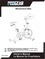
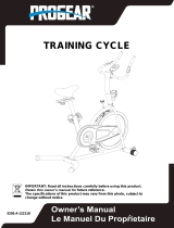
OWNER’S MANUAL
Indoor Training Bike
IMPORTANT: Read all instructions carefully before using this product. Retain this
owner’s manual for future reference. The specifications of this product may vary from this
photo, subject to change without notice.
Men’s Health and Women’s Health are registered trademarks of Hearst Magazines, Inc
and are under license by Paradigm Health and Wellness. © 2020 Hearst Magazines, Inc
1227.1-010920

1
TABLE OF CONTENTS
SERVICE ------------------------------------------------------------------------ 2
LABEL PLACEMENTS--------------------------------------------------------- 3
IMPORTANT SAFETY GUIDELINES ------------------------------------- 4
OVERVIEW DRAWING ------------------------------------------------------ 5
PARTS LIST ---------------------------------------------------------------------- 6
HARDWARE & TOOLS PACK---------------------------------------------- 8
ASSEMBLY --------------------------------------------------------------------- 9
OPERATIONS & ADJUSTMENTS ----------------------------------------- 16
TRANSPORTATION ----------------------------------------------------------- 20
MAINTENANCE & TROUBLESHOOTING ----------------------------- 21
WARRANTY -------------------------------------------------------------------- 22
PARTS REQUEST FORM ----------------------------------------------------- 23

2
SERVICE
IMPORTANT: FOR NORTH AMERICA ONLY
For damaged or defective product, questions, replacement parts or any other service
support, please contact our customer service department
(8:00 AM - 5:00 PM Pacific Standard Time, Monday thru Friday) by the below methods:
For The Best Service, please Email:
Response Time: 1-2 Business Days
Emailing us with the information above will be the best method to receive a response during
peak business hours
Website:
www.paradigmhw.com
Toll-Free:
1-844-641-7924
Response time may vary via calling
Refer to our email for the best response time
Please have the following information ready when requesting for service:
Your name
Phone number
Model number
Serial number
Part number
Proof of Purchase
For damaged or defective product please contact our customer service before returning to
the store.
Paradigm Health & Wellness, Inc.
1189 Jellick Ave.
City of Industry, CA 91748, USA

3
LABEL PLACEMENTS

4
IMPORTANT SAFETY GUIDELINES
Basic precautions should always be followed, including the following safety guidelines
when using this equipment. Read all of the guidelines before using this equipment.
1. Before exercising and to avoid injuring your muscles, it is highly recommended that you
perform warm-up exercises for each muscle group.
2. Make sure all the components are not damaged and are in working order before using. This
equipment should be placed on a stable, flat surface. Using a mat or similar, covering material
on the ground is recommended.
3. Wear proper fitness apparel when using this equipment. Do not wear loose clothing or
accessories that may get caught by any part of the equipment.
4. Make sure all the components are not damaged and are in working order before using this
equipment.
5. Remember to tighten the pedaling straps. Keep dry. Do not operate the equipment in wet or
moist condition.
6. Do not use the equipment outdoors. This equipment is for household use only.
7. Only perform maintenance or adjustments that are instructed in this manual. Should any
problems arise, discontinue usage of the equipment and consult with our customer service.
8. Only one person should be on the equipment at a time. Keep children and pets away from the
product at all times. This machine is designed for adults only.
9. Be careful to always hold onto the handlebars when you’re mounting and dismounting. Be
careful to have the pedals at their lowest point when stepping off.
10. Hold onto the handlebars and use both the pedals in tandem to ensure a smooth, effective
workout.
11. This product requires a minimum of 6 square feet around for safe operation.
12. If you feel any chest pains, nausea, dizziness, or shortness of breath, you should stop
exercising immediately, and consult your physician before continuing.
13. DO NOT pedal in reverse.
14. The maximum weight capacity for this product is 300lbs/136kg
WARNING: Before beginning any exercise program consult your physician. This is
especially important for the people who are over 35 years old or who have pre-existing
health problems.
WARNING: Risk of Personal Injury - Do not attempt to service the unit yourself.
Discontinue use and contact customer service.
CAUTION: Read all instructions carefully before operating this product. Retain this
Owner’s Manual for future reference.
!
!
!

5
OVERVIEW DRAWING

6
PARTS LIST
No.
Description
Qty
No.
Description
Qty
1
Main Frame
1
33
Rear Stabilizer End Cap
2
2
Front Post
1
34
Transporting Wheel
2
3
Handlebar
1
35
Bearing
4
4
Seat Bracket
1
36
Hex Bolt M6*12
2
5
Seat Post
1
37
Hex Bolt M6*15
2
6
Front Stabilizer
1
38
Adjustable Leveler
5
7
Rear Stabilizer
1
39
Fly Wheel
1
8
Magnet Plate
1
40
Fly Wheel Cover
2
9
Brake Plate
1
41
Self-Tapping Phillips Screw
6
10
Brake Bracket
1
42
Bearing
2
11
Device Holder
1
43
Axle
1
12
Holder Bracket
1
44
Thin Hex Nut M12
3
13
Self-Tapping Phillips Screw
ST4.2*13*Φ8
2
45
Thin Hex Nut M12
1
14
Bushing
1
46
Flange Nut M12
2
15
Spring Knob
2
47
U Bracket
1
16
Hex Bolt M5*8*Φ10
1
48
Eye Bolt
1
17
Hex Bolt M8*45
2
49
Nylon Nut M6
8
18
Hex Bolt M8*16
1
50
Idler Axle
1
19
Spring Washer d8
7
51
Idler Pulley
1
20
Washer d8
7
52
Flange Nut M10
1
21
Handlebar Cover
1
53
Wave Washer d12
1
22
Self-Tapping Phillips Screw
ST4.2*16*Φ8
4
54
Shaft Ring d12
2
23
Seat
1
55
Crank Axle
1
24
Round Knob
1
56
Bearing
2
25
Washer d10*Φ30*2.5
1
57
Belt Pulley
1
26
Oval End Cap
2
58
Hex Nut M6
4
27
Seat Post Bushing
1
59
Speed Sensor
1
28
Self-Tapping Phillips Screw
ST3.5*10*Φ7
8
60
Belt
1
29
Hex Bolt M6*8*Φ12
1
61
Shaft Ring d20
1
30
Sensor Bracket
1
62
Wave Washer d21
1
31
Hex Bolt M8*20
4
63
Spacer
1
32
Front Stabilizer End Cap
2
64L
Left Crank
1

7
PARTS LIST
No.
Description
Qty
No.
Description
Qty
64R
Right Crank
88
Hex Bolt M6*10
1
65
Crank Cap
2
89
Washer Φ8.5
1
66L
Left Pedal
1
90
Washer d7.8
1
66R
Right Pedal
1
91
Spring
1
67
Flange Nut M10
1
92
Wool Pad
1
68
Bluetooth Console 0515
1
93
Brake Plate
1
69
Self-Tapping Phillips Screw
ST3.5*10
2
94
Phillips Screw d7.8
4
70
Self-Tapping Phillips Screw
ST4.2*19
9
95
Washer d5
4
71
Tension Knob
1
96
Brake Wire
1
72
Phillips Screw M5*10
2
97
Left Cover
1
73
Washer d5
2
98
Right Cover
1
74
Bottle Holder
1
99
Front Side Cover
2
75
Square Magnet
5
100
Rear Side Cover
2
76
Magnet Bracket
2
101
Upper Cover
2
77
Self-Tapping Phillips Screw
ST3*10
8
102
Left Protective Cover
1
78
Magnet Shaft
1
103
Right Protective Cover
1
79
Tension Knob Cover
1
104
Left Brake Cover
1
80
Washer ST3*10
2
105
Right Brake Cover
1
81
Spring Washer d6
2
106L
Left Nylon Nut
1
82
Hex Bolt M6*16
2
106R
Right Nylon Nut
1
83
Hex Bolt M6*62
1
107
Self-Tapping Phillips Screw
ST4.2*8
6
84
Hex Nut M6
2
108
Brake Handle
1
85
Spring Φ1.5
2
109
Phillips Screw M6*16
2
86
Hex Bolt M6*16
2
110
Spring
1
87
Phillips Screw M5*16
1

8
HARDWARE & TOOLS PACK

9
ASSEMBLY
Remove the Metal Tubes (B) and two Flywheel Support Blocks from the Main Frame (1) by
using 6mm Allen Wrench provided. Discard the metal tubes and hardware, they will not be used in
assembly. These parts were only needed to protect the frame during shipping and are not needed
for the assembly of the bike.
Tool:
6mm Allen Wrench 1PC

10
ASSEMBLY
Step 1
1a. Front Stabilizer Installation: Lift up the front of the Main Frame (1), and attach the Front
Stabilizer (6) onto the front curve of the Main Frame (1) using two Hex Bolts (31), two Spring
Washers (19) and two Washers (20) by using the 6mm Allen Wrench provided until they are firm
and secure.
1b.Rear Stabilizer Installation: Lift up the rear of the Main Frame (1), and attach the Rear
Stabilizer (7) onto the rear curve of the Main Frame (1) using two Hex Bolts (31), two Spring
Washers (19) and two Washers (20) by using the 6mm Allen Wrench provided until they are firm
and secure.
(20) Washer
4PCS
Tool:
6mm Allen Wrench 1PC
(19) Spring Washer
4PCS
(31) Hex Bolt
4PCS
Hardware:

11
ASSEMBLY
Tip: Only turn the pedals in the direction instructed. The left and right pedals have different
turning directions for installation. The Cranks, Pedals, Pedal Shafts, Pedal Nuts, and Pedal
Straps are marked “R” for Right and “L” for Left.
Step 2
2a. Installing The Left Pedal Onto The Left Crank: Remove the Left Pedal Nut (106L). Insert the
Left Pedal (66L) perfectly straight into the threaded hole in the Left Crank (64L). Turn the pedal
shaft by hand in a COUNTER-CLOCKWISE direction until snug. Use the 13 – 15mm Wrench to
fully tighten the Left Pedal (7). Attach the Left Pedal Nut (86) to the protruding shaft in a
CLOCKWISE direction. Use both the 17-15mm Wrench & Multi-Hex Tool with Phillips
Screwdriver to simultaneously tighten the Left Pedal (66L) and the Left Pedal Nut (106L). Only
tighten in the directions instructed.
2b. Installing The Right Pedal Onto The Right Crank: Remove the Right Pedal Nut (106R)
Insert the Right Pedal (66R) perfectly straight into the threaded hole in the Right Crank (64R).
Turn the pedal shaft by hand in a CLOCKWISE direction until snug. Use the 13 – 15mm Wrench to
fully tighten the Right Pedal (66R). Attach the Right Pedal Nut (106R) to the protruding shaft in a
COUNTER-CLOCKWISE direction. Use both the 17-15mm Wrench & Multi-Hex Tool with
Phillips Screwdriver to simultaneously tighten the Right Pedal (66R) and the Right Pedal Nut
(106R). Only tighten in the directions instructed.
Important: Screw Right Foot
Pedal (66R) into right crank
clockwise!
Screw Left Foot Pedal (66L) into
Left crank counter-clockwise!
*The Cranks, Pedal Shafts, and
Foot Pedals are marked “R” for
Right and “L” for Left.
Tool:
17,19mm Wrench
1 PC
Multi-Hex Tool with
Phillips Screwdriver
1PC

12
ASSEMBLY
Step 3
3a. Installing the Front Post: Loosen The Spring Knob (15) slightly by turning it Counter-Clockwise
then Pull out the Spring Knob (15) and insert the Front Post (2) into the Main Frame (1 and
tighten The Spring Knob (15) by turning it Clockwise.
NOTE: When adjusting the height of the handlebar post, the MAX line should not be higher
than the edge of the plastic bushing.
3b. Installing the Handlebar: Attach the Handlebar (3) onto the Front Post (2) with two Hex
Bolts (17), one Hex Bolt (18), three Spring Washers (19) and three Washers (20) by using 6mm
Allen Wrench provided. Attach the Handlebar Cover (21) onto the Handlebar (3).
3c. Lift up the Device Holder (11).
Tool:
6mm Allen Wrench 1PC
(17) Hex Bolt
2PCS
(19) Spring Washer
3PCS
(20) Washer
3PCS
(18) Hex Bolt
1PC
Hardware:

13
ASSEMBLY
Step 5
5a. Installing the Seat: Attach the Seat Bracket (4) onto the Seat Post (5) and secure with one
Washer (25) and Round Knob (24). Insert the Seat Post (5) onto the Main Frame (1) with Spring
Knob (15).
Tip: When adjusting the height of Seat Post, the MAX line cannot be higher than the edge of
the plastic bushing.
(25) Washer
1PC
(24) Round Knob
1PC
15

14
ASSEMBLY
Step 6
6a. Hardware Removal: Remove two Phillips Screws (72) and two Washers (73) from the Main
Frame (1) by using 6mm Allen Wrench with Phillips Screwdriver provided.
6b. Installing the Bottle Holder: Attach the Bottle Holder (74) onto the Main Frame (1) with two
Phillips Screws (72) and two Washers (73) by using Multi-Hex Tool with Phillips Screwdriver
provided.
Tool:
Multi-Hex Tool with
Phillips Screwdriver
1PC

15
ASSEMBLY
STEP 8
8a. BATTERY INSTALLATION: Remove the Battery Cover from the Bluetooth Box (68) and
install Two AAA batteries provided into the battery tray in the correct polarity.
Please be sure to install batteries in correct order or damage will occur.
When the batteries are installed the red battery indicator light will blink three times.
NOTE* When the batteries become low the red battery indicator light will blink once every 4
seconds. When there is good battery power the red indicator light will blink three times quickly.

16
OPERATIONS & ADJUSTMENTS
Adjusting the Adjustable Leveler
Turn the Adjustable Levelers (38) on the Front and Rear Stabilizers (6/7) as needed to level the
bike
Adjusting the Handlebar Height
Loosen The Spring Knob (15) slightly by turning it
Counter-Clockwise then Pull out the Spring Knob (15) and
then slide the Handlebar Post (2) up or down to a suitable
position. Lock the Handlebar Post (2) in place by releasing
the Spring Knob (15) and sliding the Handlebar Post (2)
up or down slightly until the Spring Knob (15) "pops" into a
locked position and secure it by turning the Spring Knob
(15) Clockwise. NOTE: When adjusting the height of the
handlebar post, the STOP line cannot higher than the edge of the plastic bushing.

17
OPERATIONS & ADJUSTMENTS
Adjusting the Seat Height
Loosen The Spring Knob (15) slightly by turning it Counter-Clockwise then Pull out the Spring
Knob (15) and then slide the Seat Post (5) up or down to a suitable position. Lock the Seat Post (5)
in place by releasing the Spring Knob (15) and sliding the Seat Post (5) up or down slightly until
the Spring Knob (15) "pops" into a locked position. Then tighten the Spring Knob (15) in a
clockwise direction.
NOTE: When adjusting the height of seat post, the STOP line cannot be higher than
the edge of plastic bushing.
Adjusting the Seat Forward or Back
Loosen the Round Knob (24) by turning it in a
Counter-Clockwise direction. Slide the Seat Slide Tube (4)
forward or backward to a suitable position. Lock the Seat
Slide Tube (4) in place by turning the Round Knob (24) in
a clockwise direction.
15

18
OPERATIONS & ADJUSTMENTS
Adjusting the Seat angle:
Using the 13mm side of the 13-15mm Wrench loosen the nuts that secure the seat to the Seat
Post (5). Adjust to desired angle and Re-tighten the nuts securely.
Seat Nut
/


