
VLT
®
FCD Series
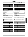
■ Contents
Introduction to FCD 300
................................................................................ 3
Software version ...................................................................................................... 3
High voltage warning ............................................................................................... 4
These rules concern your safety ............................................................................... 4
Warning against unintended start ............................................................................. 4
Installation ........................................................................................................... 7
Mechanical measurements ..................................................................................... 7
Mechanical dimensions, FCD, motor mounting ........................................................ 7
Mechanical dimensions, stand alone mounting ........................................................ 7
Mechanical installation ............................................................................................. 8
General information about electrical installation ...................................................... 10
Electronics purchased without installation box ....................................................... 10
EMC-correct electrical installation .......................................................................... 11
Diagram ................................................................................................................. 13
RFI switches J1, J2 ................................................................................................ 13
Location of terminals .............................................................................................. 14
Mains connection ................................................................................................... 16
Pre-fuses ................................................................................................................ 16
Motor connection ................................................................................................... 16
Direction of motor rotation ..................................................................................... 16
Mains and motor connection with service switch ................................................... 16
Connection of HAN 10E motor plug for T73 .......................................................... 16
Parallel connection of motors ................................................................................. 17
Motor cables .......................................................................................................... 17
Motor thermal protection ....................................................................................... 17
Brake resistor ......................................................................................................... 17
Control of mechanical brake .................................................................................. 18
Electrical installation, control cables ....................................................................... 19
Connection of sensors to M12 plugs for T53, T63, T73 ........................................ 20
Electrical installation, control terminals ................................................................... 21
PC communication ................................................................................................ 21
Relay connection ................................................................................................... 21
Connection examples ............................................................................................ 22
Programming, FCD 300 ............................................................................... 26
The LCP 2 control unit, option ............................................................................... 26
Parameter selection ............................................................................................... 29
Operation & Display ............................................................................................... 31
Setup configuration ................................................................................................ 31
Load and Motor ..................................................................................................... 39
DC Braking ............................................................................................................ 43
Motortype, par, 147 - FCD 300 ............................................................................. 48
References & Limits ............................................................................................... 49
Handling of references ........................................................................................... 49
Reference function ................................................................................................. 53
Inputs and outputs ................................................................................................. 57
Special functions .................................................................................................... 66
PID functions ......................................................................................................... 68
Handling of feedback ............................................................................................. 70
Serial communication for FCD 300 ........................................................................ 77
MG.04.B7.02 - VLT is a registered Danfoss trademark
1

VLT
®
FCD Series
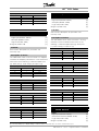
Control Word according to FC protocol ................................................................. 81
Status Word according to FC Profile ...................................................................... 83
Fast I/O FC-profile ................................................................................................. 84
Control word according to Fieldbus Profile ............................................................ 84
Status word according to Profidrive protocol ......................................................... 85
Serial communication ............................................................................................. 88
Technical functions ................................................................................................ 96
All about FCD 300 ......................................................................................... 101
Service ................................................................................................................. 101
Warnings/alarm messages ................................................................................... 102
Warning words, extended status words and alarm words ................................... 105
Aggressive environments ...................................................................................... 106
Cleaning ............................................................................................................... 106
Derating for running at low speed ........................................................................ 107
Galvanic isolation (PELV) ...................................................................................... 107
Derating for air pressure ...................................................................................... 108
Emission test results according to generic standards and PDS product standard 108
General technical data ......................................................................................... 109
Ordering form - FCD 300 ..................................................................................... 115
Technical data, mains supply 3 x 380 - 480 V ..................................................... 116
Available literature ............................................................................................... 117
Supplied with the unit ........................................................................................... 117
Factory Settings ................................................................................................... 118
Index .................................................................................................................... 125
MG.04.B7.02 - VLT is a registered Danfoss trademark
2

VLT
®
FCD Series
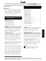
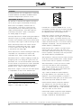
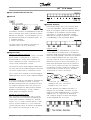
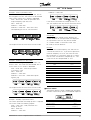
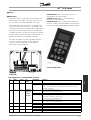
Introduction to FCD
300
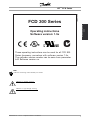
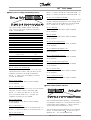
195NA195.12
FCD 300 Series
Operating instructions
Software version: 1.5x
These operating instructions can be used for all FCD 300
Series frequency converters with software version 1.5x.
The software version number can be seen from parameter
640 Software version no.
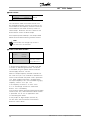
NB!:
Indicates something to be noted by the reader.
Indica
tes a general warning.
Indicates a high-voltage warning.
MG.04.B7.02 - VLT is a registered Danfoss trademark
3

VLT
®
FCD Series
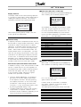
■High voltage warning
The voltage of the frequency converter
is dangerous whenever the converter
is connected to mains. Incorrect fitting
of the motor or frequency converter may cause
damage to the equipment, serious injury or death.
Consequently, it is essential to comply with the
instructions in this manual as well as local and
national rules and safety regulations.
■These rules concern your safety
1. The frequency converter must be disconnected from
the mains if repair work is to be carried out. Check
that the mains supply has been disconnected
and that the prescribed time has passed before
removing the inverter part from the installation.
2. The [STOP/RESET] key on the optional control
panel does not disconnect the equipment from
mains and is thus not to be used as a safety switch.
3. The unit must be properly connected to the
earth, the user must be protected against the
supply voltage and the motor must be protected
against overloading pursuant to prevailing
national and local regulations.
4. The earth leakage currents are higher than 3.5 mA.
5. Protection against motor overload is not included
in the factory setting. If this function is required,
set parameter 128 Motor thermal protection to
data value ETR trip or data value ETR warning.For
the North American market: The ETR functions
provide overload protection of the motor, class
20, in accordance with NEC.
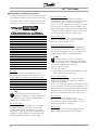
■Warning against unintended start
1. The motor can be brought to a stop by
means of digital commands, bus commands,
references or a local stop, while the frequency
converter is connected to mains. If personal
safety considerations make it necessary to
ensure that no unintended start occurs, these
stop functions are not sufficient.
2. While parameters are being changed, the
motor may start. Consequently, the stop
key [STOP/RESET] on the optional control
panel must always be activated, following
which data can be modified.
3. A motor that has been stopped may start if faults
occur in the electronics of the frequency converter,
or if a temporary overload or a fault in the supply
mains or the motor connection ceases.
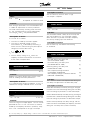
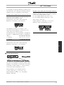
195NA194.10
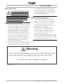
Warning:
It can be extremely dangerous to touch the electrical parts
even when the AC line supply has been disconnected.
For FCD 300: wait at least 4 minutes.
MG.04.B7.02 - VLT is a registered Danfoss trademark
4

VLT
®
FCD Series
Introduction to FCD
300
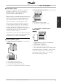
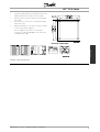
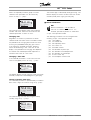
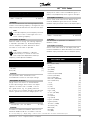
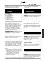
■The decentral concept
The FCD 300 Adjustable speed drive is designed
for decentral mounting, e.g. in the food and
beverage industry, in the automotive industry, or
for other material handling applications.
With the FCD 300 it is possible to utilize the cost saving
potential by placing the power electronics decentrally,
and thus make the central panels obsolete saving
cost, space and effort for installation and wiring.
The unit is flexible in its mounting options for as
well stand alone mounting and motor mounting. It
is also possible to have the unit pre-mounted on
a Danfoss Bauer geared motor (3 in one solution).
Thebasicdesignwithaplugableelectronicpartand
a flexible and "spacious" wiring box is extremely
servicefriendly and easy to change electronics
without the need for unwiring.
The FCD 300 is a part of the VLT frequency converter
family, which means similar funcionality, programming,
and operating as the other family members.
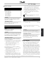
■Flexible installation options
1. Stand alone close to the motor ("wall-mounted")
• Free choice of motor brand
• Easy retrofitting to existing motor
• Easy interfacing to motor (short cable)
• Easy access for diagnosis and optimal serviceability
2. Mounted directly on the motor ("motor-mounted")
• Fair choice of motor brands
• No need for screened motor cable
3. "Pre-mounted" on Danfoss Bauer
geared motors
• A fixed combination of motor and electronics
supplied by one supplier
• Easy mounting, only one unit
• No need for screened motor cable
• Clear responsibility regarding the complete solution
Astheelectronicpartsarecommon-samefunction
of terminals, similar operation and similar parts
and spare parts for all drives - you are free to
mix the three mounting concepts.
MG.04.B7.02 - VLT is a registered Danfoss trademark
5

VLT
®
FCD Series
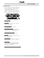
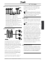
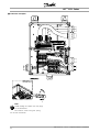
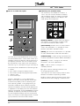
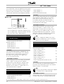
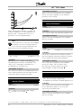
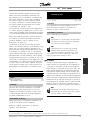
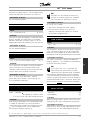
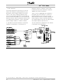
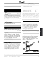
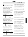
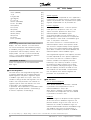
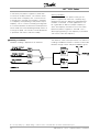
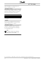
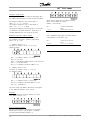
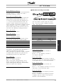
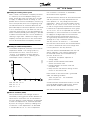
■Control principle
A frequency converter rectifies AC voltage from
the mains supply into DC voltage, following which
it changes this voltage to an AC voltage with
variable amplitude and frequency.
The motor thus receives a variable voltage and
frequency, which enables infinitely variable speed
control of three-phase, standard AC motors.
1. Mains voltage
3 x 380 - 480 V AC, 50 / 60 Hz.
2
. Rectifier
Three-phase rectifier bridge which rectifies AC
voltage into DC voltage.
3
. Intermediate circuit
DC voltage √2 x mains voltage [V].
4
. Intermediate circuit coils
Evens out the intermediate circuit current and
limits the load on mains and components (mains
transformer, cables, fuses and contactors).
5
. Intermediate circuit capacitor
Evens out the intermediate circuit voltage.
6
. Inverter
Converts DC voltage into a variable AC voltage
withavariablefrequency.
7
. Motor voltage
Variable AC voltage depending on supply voltage.
Variable frequency: 0.2 - 132 / 1 - 1000 Hz.
8
. Control card
Here is the computer that controls the inverter
which generates the pulse pattern by which
the DC voltage is converted into variable AC
voltage with a variable frequency.
MG.04.B7.02 - VLT is a registered Danfoss trademark
6

VLT
®
FCD Series
Installation
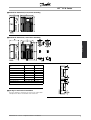
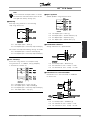
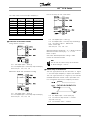
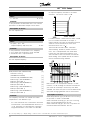
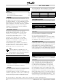
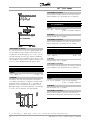
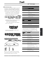
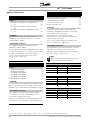
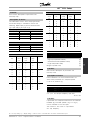
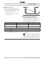
■Mechanical dimensions, FCD, motor mounting
■Mechanical dimensions, stand alone mounting
Mechanical dimensions in
mm
FCD 303-315 FCD 322-335
A 192 258
A1 133 170
B 244 300
B1 300 367
B2 284 346
C 142 151
C1 145 154
Cable Gland sizes M16, M20, M25 x 1.5 mm
Space for cable inlets and service switch handle 100-150 mm
■Spacing for mechanical installation
All units require a minimum of 100 mm air from other
components above and below the enclosure.
MG.04.B7.02 - VLT is a registered Danfoss trademark
7

VLT
®
FCD Series
■Mechanical installation
Please pay attention to the requirements
that apply to integration and remote
mounting. These must be complied
with to avoid serious injury or damage, especially
when installing large units.
The FCD 300 consists of two parts: The installation
part and the electronics part.
The two parts must be separated, and the installation
part is to be mounted first. After wiring, the electronics
is to be fixed to the installation part by the attached
6 screws. For compressing the gasket the screws
must be tightened with 2-2.4 Nm, tighten both centre
screws first, thereafter the 4 corner srews "cross over".
NB!:
Do not switch on the mains before the
6 screws are tightened.
The FCD 300 can be applied as following:
- Stand alone mounted close to the motor
- Motor mounted
or might be delivered pre mounted on a Danfoss
Bauer (geared) motor. Please contact the Danfoss
Bauer sales organisation for further information.
The frequency converter is cooled by means of air
circulation. For the unit to be able to release its
cooling air, the minimum free distance above and
below the unit must be m
inimum 100 mm.Toprotect
the unit from overheating, it must be ensured that the
ambient temperature does not rise above the max.
temperature stated for the frequency converter and
that the 24-hour average temperature is not exceeded.
The max. temperature and 24-hour average can
be seen in General technical data. If the ambient
temperature is higher, derating of the frequency
converter is to be carried out. See Derating for
ambient temperature. Pleasenotethattheservicelife
of the frequency converter will be reduced if derating
for ambient temperature is not considered.
S
tand alone mounting ("wall mounting")
For best cooling the unit should be mounted vertically,
however where space limitations require it, horizontal
mounting is allowable. The integrated 3 wall mounting
brackets in the wall mounting version can be used
for fixing the installation box to the mounting surface,
keeping a distance for possible cleaning between
the box and the mounting surface. Use the three
supplied washers to protect the paint.
Bolts must be M6 for the FCD 303 - 315
and M8 for FCD 322 - 335.
See Dimensional Drawings.
M
otor mounting
The installation box should be mounted on the
surface of the motor frame, typically instead of the
motor terminal box. The motor/geared motor may
be mounted with the shaft vertically or horizontally.
The unit mustnot be mounted upside down (the heat
sink pointing down). The cooling of the electronics is
independent on the motor cooling fan. For mounting
directly on Danfoss Bauer geared motors no adaption
plate is necessary. For motor mounting (non Danfoss
Bauer motors), an adaptor plate should usually be
applied. For that purpose a neutral plate incl gasket
and screws for attaching to the installation box is
available. The appropriate drillings and gasket for the
motor housing are applied locally. Please make sure,
that the mechanical strength of the mounting screws
and the threads are sufficient for the application. The
specified resistance against mechanical vibrations
does not cover the mounting onto a non Danfoss
Bauer motor, as the stability of the motor frame
and threads are outside Danfoss Drive’s control and
responsibility and the same applies to the enclosure
class. Please be aware, that the frequency converter
may not be used to lift the motor/geared motor.
MG.04.B7.02 - VLT is a registered Danfoss trademark
8

VLT
®
FCD Series
Installation
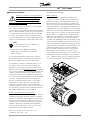
1. Prepare the adaptor plate for mounting on the motor by
drilling the fixing holes and the hole for the cables.
2. Mount the plate on the motor with the normal terminal
box gasket.
3. Knock out the 4 screw holes for mounting the adaptor
plate (outer holes).
4. Mount the terminal box onto the motor by the 4 sealing
screws and the gasket supplied.
Use the supplied star washers for securing PE
connection according to EN 60204. The screws must
be tightened with 5 Nm.
Universal adaptorplate
Allowed mounting positions
MG.04.B7.02 - VLT is a registered Danfoss trademark
9

VLT
®
FCD Series
■General information about electrical installation
■High voltage warning
The voltage of the frequency converter
is dangerous whenever the equipment is
connected to mains. Incorrect installation
of the motor or frequency converter may cause
damage to the equipment, serious injury or death.
Comply with the instructions in this manual, as well as
national and local rules and safety regulations.
Touching the electrical parts may be fatal - even after
the equipment has been disconnected from mains:
Wait at least 4 minutes for current dissipate.
NB!:
It is the responsibility of the user or installer
to ensure correct earthing and protection in
accordance with national and local standards.
■Cables
The control cable and the mains cable should be
installed separately from motor cables to prevent
noisetransfer. Asaruleadistanceof20cmis
sufficient, but it is recommended that the distance
is as great as possible, particularly when cables are
installed in parallel over large distances.
For sensitive signal cables such as telephone or data
cables the greatest possible distance is recommended.
Please note that the required distance depends on
the
installation and the sensitivity of the signal cables, and
that for this reason exact values cannot be given.
When being placed in cable trays, sensitive cables
may not be placed in the same cable tray as t
he
motor cable. If signal cables run across power
cables, this is done at an angle of 90 degrees.
Remember that all noise-filled inlet
and outlet cables
to a cabinet must be screened/armoured.
See also EMC-compliant electrical installation.
Cable glands
It must be assured that appropriat
e cable
glands needed for the environment are chosen
and carefully mounted.
■Screened/armoured cables
The screen must have low HF impe
dance, which is
achieved by a braided screen of copper, aluminium or
iron. Screen reinforcement intended for mechanical
protection, for example, is
not suitable for EMC-correct
installation. See also Use of EMC-correct cables.
■Extra protection
ELCB relays, multiple protective earthing or earthing
can be used as extra protection, provided that local
safety regulations are complied with. In the case of an
earth fault, a DC content may develop in the faulty
current. Never use an RCD (ELCB relay), type A, as
it is not suitable for DC faulty currents. If ELCB relays
are used, local regulations must be complied with.
If ELCB relays are used, they must be:
- Suitable for protecting equipment with a DC content
in the faulty current (3-phase bridge rectifier)
- Suitable for a pulse-shaped, brief discharge
on power-up
- Suitable for a high leakage current.
See also RCD Application Note MN.90.GX.02.
■High voltage test
A high voltage test can be performed by
short-circuitingterminalsU,V,W,L1,L2andL3,
and applying max. 2160 V DC in 1 sec. between
this short-circuit and PE-terminal.
■Electronics purchased without installation box
If the electronic part is purchased without the
Danfoss installation part, the earth connection
must be suitable for high leakage current. Use
of original Danfoss installation box or installation
kit 175N2207 is recommended.
■Caution
PE connection
T
he metal pin in the corner(s) of the
electronic part and the bronze spring in the
corner(s) of the installation box are essential
for the protective earth connection. Mak
e sure they
are not loosened, removed, or violated in any way.
MG.04.B7.02 - VLT is a registered Danfoss trademark
10

VLT
®
FCD Series
Installation
NB!:
Do not plug/unplug the electronic part with
mains voltage switched on.
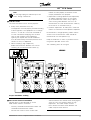
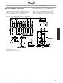
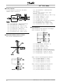
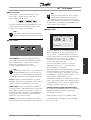
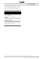
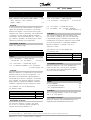
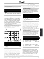
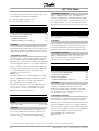
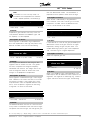
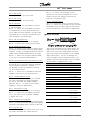
■Protective earth
The earth connection serves several purposes.
• Safety earth (Protective earth, PE)
The equipment must be properly earthed according
to local regulation. This equipment has a leakage
current > 3.5 mA AC. It must be connected to
an earth connection complying with the local
rules for high leakage current equipment.
Typically, this implies that the PE conductors
must be mechanically enhanced (minimum cross
section 10 mm
2
) or duplicated
• Noise "clamping" (high frequencies)
Stable communication between units call for
screening of the communication cables (1).
Cables must be properly attached to screen
clamps provided for that purpose.
• Equalisation of voltage potential (low frequencies)
To reduce alignment currents in the screen
of the communication cable, always apply a
short earthing cable between units that are
connected to the same communication cable (2)
or connect to an earthed frame (3).
• Potential equalization: All metal parts, where the
motors are fastened, must be potential equalized
PE connections, voltage equalising cables and the
screen of the communication cable should be
connected to the same potential (4).
Keep the conductor as short as possible and use
the greatest possible surface area.
The numbering refers to the figure.
Proper installation earthing
■EMC-correct electrical installation
General points to be observed to ensure
EMC-correct electrical installation.
- Use only screened/armoured motor cables and
screened/armoured control cables.
- Connect the screen to earth at both ends.
- Avoid installation with twisted screen ends (pigtails),
since this ruins the screening effect at high
frequencies. Use cable clamps instead.
-Don’t remove the cable screen between the
cable clamp and the terminal.
MG.04.B7.02 - VLT is a registered Danfoss trademark
11

VLT
®
FCD Series
■ATEX correct installation
The following issues must be taken into account when
installing the FCD 300 in ATEX zone 22 environments:
• Motor must be designed, tested and certified by the
motor manufacturer for variable speed application
• Motor must be designed for Zone 22 operation.
I.e. with type of protection "tD" acc. to
EN61241-0 and -1 or EN50281-1-1.
• Motor must be provided with thermistor protection.
The thermistor protection must either be connected
to an external thermistor relay, with EC Type
Examination Certificate or compatible with
the FCD 300 thermistor input.
If the FCD 300 thermistor protection is used,
the thermistor must be wired to terminals
31a and 31b, and thermistor trip activated by
programming parameter 128 to thermistor trip
[2]. See parameter 128 for further details.
• Cable entries must be chosen for the enclosure
protection to be maintained. It must also be
ensured that the cable entries comply with the
requirements for clamping force and mechanical
strengths as described in EN 50014:2000.
• The FCD must be installed with appropriate earth
connecting according to local/national regulations.
• The installation, inspection and maintenance of
electrical apparatus for use in combustible dusts,
must only be carried out by personnel that is
trained and familiar with the concept of protection.
For a declaration of conformity, please consult
your local Danfoss representative.
MG.04.B7.02 - VLT is a registered Danfoss trademark
12

VLT
®
FCD Series
Installation
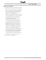
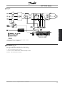
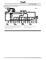
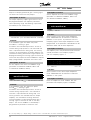
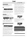
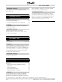
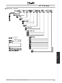
■Diagram
* Integrated brake and mechanical brake control
and external 24 V are options.
■RFI switches J1, J2
J1 and J2 must be removed at IT mains and
delta grounded mains with phase to earth voltage
> 300 V also during earth failure.
J1 and J2 can be removed to reduce leakage current.
Caution: No correct RFI filtering.
MG.04.B7.02 - VLT is a registered Danfoss trademark
13

VLT
®
FCD Series
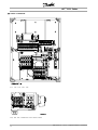
■Location of terminals
T11, T12, T16, T52, T56
T22, T26, T62, T66versions with service switch
MG.04.B7.02 - VLT is a registered Danfoss trademark
14

VLT
®
FCD Series
Installation
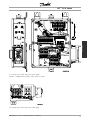
T73 version with motor plug and sensor plugs
Version is supplied from Danfoss with wiring as shown
T63
versionwithserviceswitch(nomotorplug)
MG.04.B7.02 - VLT is a registered Danfoss trademark
15

VLT
®
FCD Series
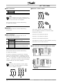
■Mains connection
No. 91 92 93 Mains voltage 3 x 380-480 V
L1 L2 L3
PE Earth connection
NB!:
Please check that the mains voltage fits the
mains voltage of the frequency converter, which
can be seen from the nameplate.
See Technical data for correct dimensioning
of cable cross-section.
■Pre-fuses
See Technical data for correct dimensioning
of pre-fuses.
■Motor connection
Connect the motor to terminal
s 96, 97, 98.
Connect earth to PE-terminal.
No. 96 97 98 Motor voltage 0-100% of mains voltage
UVW3 wires out of motor
U1
W2
V1
U2
W1
V2
6 wires out of motor, Delta connected
U1 V1 W1 6 wires out of motor, Star connected
U2, V2, W2 to be interconnected
separately (optional terminal block)
PE Earth connection
See Technical data for correct dimensioning
of cable cross-section.
All types of three-phase asynchronous standard
motors can be connected to a frequency converter.
Normally, small motors are star-connected (230/400
V,
/ Y). Large motors are delta-connected (400/690
V,
/ Y). The correct connection mode and voltage
can be read from the motor nameplate.
NB!:
In motors without phase insulation paper,
an LC filter should be fitted on the output
of the frequency converter.
■Direction of motor rotation
The factory setting is for clockwise rotation
with the frequency converter transformer output
connected as follows:
Terminal 96 connected to U-phase.
Terminal 97 connected to V-phase.
Terminal 98 connected to W-phase.
The direction of rotation can be changed by switching
two phases on the motor terminals.
■Mains and motor connection with service switch
MG.04.B7.02 - VLT is a registered Danfoss trademark
16

VLT
®
FCD Series
Installation
■Connection of HAN 10E motor plug for T73
HAN 10E pin no 1 - Motor phase U
HAN 10E pin no 2 - Motor phase V
HAN 10E pin no 3 - Motor phase W
HAN 10E pin no 4 - Motor brake, see Operating
Instructions MG.04.BX.YY, terminal 122
HAN 10E pin no 5 - Motor brake, see Operating
Instructions MG.04.BX.YY, terminal 123
HAN 10E pin no 9 - Motor thermistor, see O p erating
Instructions MG.04.BX.YY, terminal 31A
HAN 10E pin no 10 - Motor thermistor, see
Operating Instructions MG .04.BX.YY, terminal 31B
PE = protective earth
■Parallel connection of motors
The frequency converter is able to control several
motors connected in parallel. If the motors are
to have different rpm values, use motors with
different rated rpm values. Motor rpm is changed
simultaneously, which means that the ratio between
the rated rpm values is maintained across the range.
The total current consumption of the motors is
not to exceed the maximum rated output current
I
INV
for the frequency converter.
Problems may arise at the start and at low rpm
values if the motor sizes are widely different. This
is because the small motors’ relatively high ohmic
resistance in the stator calls for a higher voltage
at the start and at low rpm values.
In systems with motors connected in parallel, the
electronic thermal relay (ETR) of the frequency
converter cannot be used as motor protection for
the individual motor. For this reason further motor
protection must be used, e.g. thermistors in each
motor (or an individual thermal relay).
NB!:
Parameter 107 Automatic motor tuning, AMT
cannot be used when motors are connected
in parallel. Parameter 101 Torque characteris tic
must be set to Special motor cha racteristics [8]
when motors are connected in parallel.
■Motor cables
See Technical data for correct dimensioning of motor
cable cross-section and length. Always comply with
national and local regulations on cable cross-section.
NB!:
If an unscreened/unarmoured cable is used,
some EMC requirements are not complied with,
see EMC test results in the Design Guide.
If the EMC specifications regarding emission are
to be complied with, the motor cable must be
screened/armoured, unless otherwise stated for the
RFI filter in question. It is important to keep the motor
cable as short as possible so as to reduce the noise
level and leakage currents to a minimum. The motor
cable screen must be connected to the metal cabinet
of the frequency converter and to the metal cabinet of
the motor. The screen connections are to be made
with the biggest possible surface area (cable clamp).
This is enabled by different installation devices in
different frequency converters. Mounting with twisted
screen ends (pigtails) is to be avoided, since these
spoil the screening effect at high frequencies. If it
is necessary to break the screen to install a motor
isolator or motor relay, the screen must be continued
at the lowest possible HF impedance.
■Motor thermal protection
The electronic thermal relay in UL-approved frequency
converters has received the UL-approval for single
motor protection, when parameter 128 Motor thermal
protection has been set for ETR Trip and parameter
105 Motor current, I
M, N
has been programmed to
the rated motor current (see motor nameplate).
MG.04.B7.02 - VLT is a registered Danfoss trademark
17

VLT
®
FCD Series
■Brake resistor
No. 81 (optional
function)
82 (optional
function)
Brake resistor
terminals
R- R+
The connection cable to the brake resistor must
be screened/armoured. Connect the screen to the
metal cabinet of the frequency conver
ter and to the
metal cabinet of the brake resistor by means of
cable clamps. Dimension the cross-section of the
brake cable to match the brake to
rque.
See chapter Dynamic Brak
ing in the Design Guide
MG.90.FX.YY for dimensionering of brake resistors.
NB!:
Please note that voltages up to 850 V
DC occur on the te
rminals.
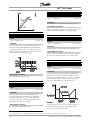
■Control of mechanical brake
No. 122 (optional
function)
123
(optional
function)
MBR+ MBR- Mechanical brake
(UDC=0.45 X Mains
Voltage) Max 0.8 A
In lifting/lowering applications you need to be able
to control an electromagnetic brake. The brake
is controlled using the special mechanical brake
control/supply terminals 122/123.
When the output frequency exceeds the brake cut
out value set in par. 138, the brake is released if the
motor current exceeds the preset value in parameter
140. When stopping the brake is engaged when
the output frequency is less than the brake engaging
frequency, which is set in par. 139.
If the frequency converter is at alarm status
or in an overvoltage situation the mechanical
brake is cut in immediately.
If not using the special mechanical brake control/supply
terminals (122-123), select Mechanical brake control
in parameter 323 or 341 for applications with
an electromagnetic brake.
A relay output or digital output (terminal 46)
can be used. See Connection of mec hanical
brake for further details.
MG.04.B7.02 - VLT is a registered Danfoss trademark
18

VLT
®
FCD Series
Installation
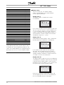
■Electrical installation, control cables
Control cables must be screened/armoured. The
screen must be connected to the frequency converter
chassis by means of a clamp. Normally, the screen
must also be connected to the chassis of the
controlling unit (use the instructions for the unit in
question). In connection with very long control cables
and analogue signals, in rare cases depending on
the installation, 50/60 Hz earth loops may occur
because of noise transmitted from mains supply
cables. In this connection, it may be necessary
to break the screen and possibly insert a 100 nF
capacitor between the screen and the chassis.
Switches S101-104
Bus line coils, leave switches ON
MG.04.B7.02 - VLT is a registered Danfoss trademark
19

VLT
®
FCD Series
■Connection of sensors to M12 plugs for
T53, T63, T73
For rating specifications see the Operating Instructions
MG.04.BX.YY, digital inputs terminals 18, 19, 29, 33.
Terminals 203/204 are used for sensor supply.
Terminal 203 = common
Terminal 204 = +24 V
Terminals 201/202 can be used for a
separate 24 V supply.
MG.04.B7.02 - VLT is a registered Danfoss trademark
20
Page is loading ...
Page is loading ...
Page is loading ...
Page is loading ...
Page is loading ...
Page is loading ...
Page is loading ...
Page is loading ...
Page is loading ...
Page is loading ...
Page is loading ...
Page is loading ...
Page is loading ...
Page is loading ...
Page is loading ...
Page is loading ...
Page is loading ...
Page is loading ...
Page is loading ...
Page is loading ...
Page is loading ...
Page is loading ...
Page is loading ...
Page is loading ...
Page is loading ...
Page is loading ...
Page is loading ...
Page is loading ...
Page is loading ...
Page is loading ...
Page is loading ...
Page is loading ...
Page is loading ...
Page is loading ...
Page is loading ...
Page is loading ...
Page is loading ...
Page is loading ...
Page is loading ...
Page is loading ...
Page is loading ...
Page is loading ...
Page is loading ...
Page is loading ...
Page is loading ...
Page is loading ...
Page is loading ...
Page is loading ...
Page is loading ...
Page is loading ...
Page is loading ...
Page is loading ...
Page is loading ...
Page is loading ...
Page is loading ...
Page is loading ...
Page is loading ...
Page is loading ...
Page is loading ...
Page is loading ...
Page is loading ...
Page is loading ...
Page is loading ...
Page is loading ...
Page is loading ...
Page is loading ...
Page is loading ...
Page is loading ...
Page is loading ...
Page is loading ...
Page is loading ...
Page is loading ...
Page is loading ...
Page is loading ...
Page is loading ...
Page is loading ...
Page is loading ...
Page is loading ...
Page is loading ...
Page is loading ...
Page is loading ...
Page is loading ...
Page is loading ...
Page is loading ...
Page is loading ...
Page is loading ...
Page is loading ...
Page is loading ...
Page is loading ...
Page is loading ...
Page is loading ...
Page is loading ...
Page is loading ...
Page is loading ...
Page is loading ...
Page is loading ...
Page is loading ...
Page is loading ...
Page is loading ...
Page is loading ...
Page is loading ...
Page is loading ...
Page is loading ...
Page is loading ...
Page is loading ...
Page is loading ...
Page is loading ...
-
 1
1
-
 2
2
-
 3
3
-
 4
4
-
 5
5
-
 6
6
-
 7
7
-
 8
8
-
 9
9
-
 10
10
-
 11
11
-
 12
12
-
 13
13
-
 14
14
-
 15
15
-
 16
16
-
 17
17
-
 18
18
-
 19
19
-
 20
20
-
 21
21
-
 22
22
-
 23
23
-
 24
24
-
 25
25
-
 26
26
-
 27
27
-
 28
28
-
 29
29
-
 30
30
-
 31
31
-
 32
32
-
 33
33
-
 34
34
-
 35
35
-
 36
36
-
 37
37
-
 38
38
-
 39
39
-
 40
40
-
 41
41
-
 42
42
-
 43
43
-
 44
44
-
 45
45
-
 46
46
-
 47
47
-
 48
48
-
 49
49
-
 50
50
-
 51
51
-
 52
52
-
 53
53
-
 54
54
-
 55
55
-
 56
56
-
 57
57
-
 58
58
-
 59
59
-
 60
60
-
 61
61
-
 62
62
-
 63
63
-
 64
64
-
 65
65
-
 66
66
-
 67
67
-
 68
68
-
 69
69
-
 70
70
-
 71
71
-
 72
72
-
 73
73
-
 74
74
-
 75
75
-
 76
76
-
 77
77
-
 78
78
-
 79
79
-
 80
80
-
 81
81
-
 82
82
-
 83
83
-
 84
84
-
 85
85
-
 86
86
-
 87
87
-
 88
88
-
 89
89
-
 90
90
-
 91
91
-
 92
92
-
 93
93
-
 94
94
-
 95
95
-
 96
96
-
 97
97
-
 98
98
-
 99
99
-
 100
100
-
 101
101
-
 102
102
-
 103
103
-
 104
104
-
 105
105
-
 106
106
-
 107
107
-
 108
108
-
 109
109
-
 110
110
-
 111
111
-
 112
112
-
 113
113
-
 114
114
-
 115
115
-
 116
116
-
 117
117
-
 118
118
-
 119
119
-
 120
120
-
 121
121
-
 122
122
-
 123
123
-
 124
124
-
 125
125
-
 126
126
-
 127
127


Danfoss VLT Decentral Drive FCD 300 (Legacy Product) Operating instructions
- Type
- Operating instructions
- This manual is also suitable for
Ask a question and I''ll find the answer in the document
Finding information in a document is now easier with AI
Related papers
-
Danfoss VLT AutomationDrive FC 301 Programming Guide
-
-
-
Danfoss VLT Decentral Drive FCD 300 (Legacy Product) Installation guide
-
Carrier VLT 2000 Specification
-
Danfoss VLT® 2800 Operating instructions
-
-
-
-
Other documents
-
Mitsubishi Electric GM-J2 GEARED MOTOR User manual
-
RAD Data comm Modular Access Device with Integrated User manual
-
 Dantherm CDP/CDP-T/CDF 40-50-70 Modbus Protocol Owner's manual
-
Honeywell Universal Digital Controller UDC 3300 User manual
-
Shinko FCD, FCR-15A User manual
-
Trane TR200 Series Programming Manual
-
-
Electronics International FCD-TR1 Operating instructions
-
 Body-Solid FCD Owner's manual
-
Gossen MetraWatt SINEAX V604s Operating instructions

