Page is loading ...

MODEL CX617
MODEL CX617
12" DRILL PRESS
USER MANUAL
Version 2.0

2
TABLE OF CONTENTS
General Safety Instructions for Machines ............................................................... 3
Specific Safety Instructions ..................................................................................... 4
CX617 Features ...................................................................................................... 5
Physical Features ................................................................................................... 6
Proper Grounding ................................................................................................... 7
Unpacking ............................................................................................................... 8
Setup ...................................................................................................................... 8
Operating Controls .................................................................................................. 8
Test Run ................................................................................................................. 9
Operation ................................................................................................................ 10
Installing the Arbor and Chuck ................................................................................ 10
Removing the Chuck ............................................................................................... 10
Turning the Head .................................................................................................... 11
Indication of Extreme Speeds and Feed ................................................................. 11
Speed for High Speed Steel Drills........................................................................... 12
Maintenance ........................................................................................................... 12
Drive Belt Replacement .......................................................................................... 13
Lubrication .............................................................................................................. 13
CX617 Wiring .......................................................................................................... 14
Troubleshooting ...................................................................................................... 15
Parts Diagram and Parts List ............................................................................. 16-19
Parts List ................................................................................................................. 18
Warranty ................................................................................................................. 20

3
GENERAL SAFETY INSTRUCTIONS
FOR MACHINES
Extreme caution should be used when operating all power tools. Know your power
tool, be familiar with its operation, read through the user manual, and practice safe
usage procedures at all times.
ALWAYS read and understand the
user manual before operating the
machine.
CONNECT your machine ONLY to the
matched and specific power source.
ALWAYS wear safety glasses
respirators, hearing protection and
safety shoes, when operating your
machine.
DO NOT wear loose clothing or
jewelry when operating your machine.
Wear protective hair covering.
A SAFE ENVIRONMENT is
important. Keep the area free of dust,
dirt and other debris in the immediate
vicinity of your machine.
BE ALERT! DO NOT use prescription
or other drugs that may affect your
ability or judgment to safely use your
machine.
DISCONNECT the power source when
changing drill bits, hollow chisels,
router bits, shaper heads, blades,
knives or making other adjustments or
repairs.
NEVER leave a tool unattended while it
is in operation.
NEVER allow unsupervised or untrained
person to operate the machine.
NEVER reach over the table when the
tool is in operation.
ALWAYS keep blades, knives and bits
sharpened and properly aligned.
ALL OPERATIONS MUST BE
performed with the guards in place to
ensure safety.
ALWAYS use push sticks and feather
boards to safely feed your work through
the machine.
ALWAYS make sure that any tools used
for adjustments are removed before
operating the machine.
ALWAYS keep bystanders safely away
while the machine is in operation.
NEVER attempt to remove jammed
cutoff pieces until the blade has come to
a full stop.

4
READ AND UNDERSTAND the user
manual before operating the CX617.
ALWAYS WEAR safety glasses for
the protection of your eyes while
operating this machine.
WEAR PROPER APPAREL. Loose
clothing, gloves neckties, rings,
bracelets, or other jewelry may get
caught in moving parts of the machine.
Wear protective hair covering to
contain long hair. Do not wear gloves
and keep your fingers and hair away
from rotating parts.
KEEP GUARDS in place. Safe guards
must be kept in place and in working
order. Do not operate the drill press
unless the chuck guard is in its
position, guarding the chuck.
MAKE SURE the work-piece is
properly clamped to the table before
operating the machine. Never hold the
work-piece by hand when using the
mill.
MAKE SURE the cutting tool is sharp,
not damaged and properly secured in
the chuck before you start the
machine.
NEVER turn the power ON with the
cutting tool contacting the work-piece.
SELECT THE PROPER SPINDLE
SPEED for the type of work and material
you are cutting. Let the spindle reach to
its full speed before beginning a cut.
DO NOT FORCE THE TOOL. Always
use the machine at the rate for which it
is designed. Do not force the machine
doing a job for which it is not designed.
NEVER LEAVE the machine
unattended while it is running.
ALWAYS turn off the power before
removing scrap pieces and cleaning the
machine.
SHOULD ANY PART of your tool be
missing, damaged or fail in any way,
shut off the machine immediately and
remove the plug from power source.
Replace any damaged or missing parts
before resuming operation.
MAKE SURE before installing and
removing any parts, servicing, cleaning
or making any adjustments, the switch is
in the “OFF” position and the cord is un-
plugged from the power source.
BEFORE OPERATING your dill press
make sure you have read and
understood all the safety instructions in
the manual and you are familiar with
your machine. If you fail to do so,
serious injury could occur.
SPECIFIC SAFETY INSTRUCTIONS
CX617 – 12" DRILL PRESS
WARNING!
The safety instructions given above can not be complete because the environment in
every shop is different. Always consider safety first as it applies to your individual
working conditions.

5
MODEL CX617 – 12" DRILL PRESS
As part of the growing line of Craftex CX-Series metalworking equipment, we are proud to offer
the CX617, a 12" Drill Press. By following the instructions and procedures laid out in this user
manual, you will receive years of excellent service and satisfaction. The CX617 is a
professional tool and like all power tools, proper care and safety procedures should be
adhered to.
Motor .............................................. 1/2HP, 120V, 60 Hz, 5A
Motor………………………………….No Load Speed: 1750RPM
Type ............................................... Belt Drive
Variable Speed ............................... 530 ~ 3100 RPM (DRO)
Capacity.......................................... 6" (chuck to column), 20" (chuck to base)
Spindle Taper ................................. MT2
Spindle Travel ................................. 3-1/8”
Chuck Capacity .............................. 5/8”
Laser .............................................. Class III, Transformed Powered
Table Size ....................................... 9.45” x 9.45
Table Tilt ......................................... 0 to 45° Left and Right
Overall Dimensions ........................ 21” L x 15.35” H x 37.4 H
Gross Weight / Net Weight…...…… 41kg / 38kg
Warranty ......................................... .3-Years
CX617 – DRILL PRESS
FEATURES

6
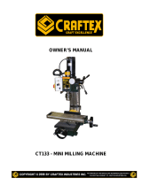
PHYSICAL FEATURES
CX617 - 12" DRILL PRESS
Pulley Cover
LED Light
ON/OFF Switch
Depth Stop
Chuck
ON/OFF Switch
with Safety Key
Work Table
Base
Table Height
Crank Handle
Rack
Feed Handles
1 HP Motor
Mounting
Holes
RPM Digital
Readout Display
Chuck Key and
Holder
Column
Table Height
Lock Handle
LED Light
Return
Spring
Variable
Speed Handle
Extension
Table Roller
Laser ON/OFF
Switch

7
PROPER GROUNDING
Grounding provides a path of least
resistance for electric current to reduce the
risk of electric shock.
CX617 is for use on a normal 110 volt
circuit. Make sure that the machine is
connected to an outlet having the same
configuration as the plug. If an adaptor plug
is used, it must be attached to the metal
screw of the receptacle. To prevent
electrical hazards, have a qualified
electrician ensure that the line is properly
wired.
The drill press should be wired with a plug
having 3 prongs to fit a 3 prong grounded
receptacle as shown in figure-1. Do not
remove the grounding prong to fit it into a 2
pronged outlet.
Figure-1 110-Volts outlet for CX617
It is strongly recommended not to use
extension cords with your CX617. Always
try to position your machine close to the
power source so that you do not need to
use extension cords.
If you really find it necessary to use an
extension cord, make sure the extension
cord does not exceed 50-feet in length and
the cord is 14-gauge to prevent motor
damage.
WARNING!
Improper connection of the equipment-
grounding conductor can result in a risk
of electric shock. Check with a qualified
electrician if you are in doubt as to
whether the outlet is properly grounded.

8
UNPACKING
To ensure safe transportation this machine
is properly packaged and shipped
completely in a crate. When unpacking,
carefully inspect the crate and ensure that
nothing has been damaged during transit.
While doing inventory, if you can not find
any part, check if the part is already
installed on the machine. Some of the parts
come assembled with the machine for the
shipping purposes.
SETUP
Before setting up your machine you should
read and understand the instructions given
in this manual.
The unpainted surfaces of this machine are
coated with a rust preventive waxy oil and
you will want to remove this before starting
assembly. Use a solvent cleaner that will
not damage painted surfaces.
MOUNTING TO
A TABLE TOP
The CX617 features two mounting holes
allowing it to be mounted to a table top
having a load capacity of approximately 38
Kg.
Figure-2 Mounting holes on the base
To mount the drill press to the table top:
Make sure the surface is flat and stable.
Position the drill press onto the table and
use the two holes on the drill press base as
a guide and drill into the table.
Secure the drill press to the table by using
lag bolts, flat washers and hex nuts (not
provided).
TABLE SUPPORT
To install the table support:
Slide the table support assembly all the way
down until it rests on the base.
Install the support lock handle to right side
of the table support as shown in figure-3.
WARNING!
CX617 is a heavy machine, do not over-
exert yourself. Use a fork truck or get the
help of an assistant for safe moving.

9
Figure-3 Installing table height lock handle
Slide the table to desired height and lock it
in position.
FEED HANDLES
To install the feed handles:
Thread the three feed handles into the
holes on the feed hub and hand tighten.
See figure-4.
Figure-4 Installing the feed handles
SPEED HANDLE
Thread the speed handle into the hole on
the speed hub and hand tighten. See
figure-5.
Figure-5 Installing feed handle
EXTENSION TABLE
ROLLER
Insert the two rods of the extension table
into the two channels at the side of the
table.
Secure the extension table by tightening the
two lock knobs underneath the table. See
figure-6.
Figure-6 Installing extension table

10
INSTALLING
THE CHUCK
Remove grease and particles from the
chuck and spindle surface with a clean
cloth.
Slide the chuck onto the arbor and then
place a block of wood under the chuck and
tap the chuck and arbor with a hammer until
it seats into the spindle.
Do not strike the chuck directly with a steel
hammer.
REMOVING THE CHUCK
Lower the chuck to its lowest position
exposing the spindle sleeve.
The spindle sleeve has a large oval hole on
both sides of it.
Rotate the chuck until the spindle hole lines
up with the hole in the spindle sleeve.
Insert the wedge and tap the wedge lightly
with a hammer.
The arbor and the chuck will release from
the spindle.
ON/OFF SWITCH
The CX617 features ON/OF switch with a
removable key which prevents from
unauthorized use when removed.
Figure-7 ON/OFF switch with removable
key
LED LIGHT & LASER
ON/OFF SWITCHES
There are two small other ON/OFF
switches on the front side of drill press. The
ON/OFF switch on the right is for the LED
light and one on the left is for the laser. See
figure-8.
Figure-8 Rocker switches for LED light and
Laser

11
TEST RUN
Once you have assembled your drill press
completely, it is then time for a test run to
make sure that it works properly and is
ready for operation.
Remove all the tools used for assembling
the machine and make sure all the guards
are in place.
If you find an unusual problem during the
test run, immediately stop the machine,
disconnect it from the power and fix the
problem before operating the machine
again.
TO TEST RUN THE MACHINE
Connect the machine to power supply.
Turn the switch to ON position. The motor
should run smoothly, without unusual
vibration and noises.
Turn the switch to OFF position and allow
the spindle to come to a complete stop.
VARIABLE SPEED
The CX617 is provided with a variable
speed to increase or decrease the spindle
speed using a speed handle.
Use the following table to determine the
recommended speed for the drill size you
are using and the type of material you are
drilling. While drilling, check the speed of
the digital speed readout located at the
front of the drill press.
Figure-9 Recommended speed for drill bit
size and material
To change the speed:
Turn the machine on.
Use the variable speed handle to change
the spindle speed.
WARNING!
Before operating the drill pres
s make
sure that you have read and understood
the instructions given in the manual and
you are familiar with the functions and
safety features on this machine. Failure
to do so may cause serious personal
injury or damage to the machine.
WARNING!
Make sure the machine is on while
changing the speed using the variable
speed handle.
DO NOT change the
speed while the drill press in OFF.

12
ADJUSTING TABLE
The table height and angle can be adjusted
on the CX617.
To adjust the table height:
Make sure the cord is disconnected from
the power source.
Loosen the lock handle, move the table to
desired height and tighten the lock handle.
Figure-10 Table adjustment controls
To adjust the table angle:
Loosen the bevel bolt shown in figure-10.
Tilt the table to the desired angle according
to the tilt scale shown in figure-11.
Figure-11 Table tilting scale
Tighten the bevel bolt.
CHANGING DRILL BIT
To insert the bit:
Make sure the cord is disconnected from
the power source.
Open the chuck wide enough to accept a
new bit.
Insert the drill bit into the chuck far enough
to obtain maximum gripping by the jaws,
but not far enough to touch the spiral
grooves of the drill bit when the jaws are
tightened.
Tighten the chuck with the chuck key.
Remove the chuck key and reconnect the
power source.
To remove a drill bit:
Disconnect the cord from the power source.
Loosen the chuck with the chuck key and
remove the bit with your hand.

13
DEPTH STOP
A drilling depth stop is provided on the left
side of the drill head. The depth stop is
consists of a threaded rod with depth
setting jam nuts. The front side of the
threaded rod has a depth scale. The jam
nuts are loosened and moved to the
desired depth on the scale. The upper jam
nut is then tightened against the lower nut.
See figure-12.
Figure-12 Depth stop
SPINDLE RETURN SPRING
The spindle is equipped with an auto-return
mechanism featuring a spring and notched
housing. The spring was properly adjusted
at the factory and should not be readjusted
unless absolutely necessary.
Do adjust the spindle return spring:
Disconnect the cord from the power source.
Place a screw driver into the loop to hold
the spring in position.
Loosen the two housing nuts. DO NOT
remove the nuts from the threaded shaft.
Do not allow the spring and spring housing
to slip out of control.
While firmly holding the spring housing,
carefully pull the spring housing out until it
clears the raised notch.
Turn the housing so that the next notch is
engaged with the raised notch.
To increase the spindle return tension, turn
the spring housing counter-clockwise.
To decrease the tension, turn the spring
housing clockwise.
Tighten the two housing nuts.
Make sure not to overtighten the nuts.
Overtightening the nuts will cause the
movement of the spindle and the feed
handles to be sluggish.
Figure-13 Spindle return spring housing

14
DRIVE BELT
REPLACEMENT
Belt tension and drill press speed is
controlled by the variable speed handle
located on the side of the machine.
To replace the drive belt:
Make sure the machine is on and loosen
the tension on the belt by using the variable
speed handle.
Now turn off the machine and disconnect
the cord from the power source.
Remove the screw securing the belt cover
and open the cover.
Remove the belt from the pulleys and
replace it with a new one.
Figure-14 Belt replacement
DO NOT turn the variable speed handle
while the machine is OFF.
Once the belt is installed properly on both
the pulleys, close the belt cover and
retighten the screw.

15
MAINTENANCE
During the life of your machine, you will
need to practice some regular maintenance
to keep your machine in peak performance
condition.
1. Check the machine everyday before
operation for; worn or damaged cord, wire,
loose nuts and bolts and make sure all the
safety devices are working properly.
2. Treat your machine with care, keep it
clean and grease and lubricate it regularly.
Only through good care you can be sure
that the working quality of the machine will
remain constant.
3. During operation, the chips which fall
onto the sliding surface should be cleaned
in a timely fashion. Frequent inspections
should be made to prevent chips from
falling into the position between the work
table and the slide ways.
4. After the operation every day, eliminate
all the chips and clean different parts of the
machine tool and apply machine tool oil to
prevent from rusting.
5. Make sure your work area is well
ventilated.
LUBRICATION
Following are lubrication recommendations
for drill press components.
SPINDLE PULLEY DRIVE
Lubricate spindle occasionally with light
grease.
QUILL, TABLE, AND COLUMN
Lubricate with light film of oil.
TABLE LIFT RACK
Lubricate regularly with SAE20 oil (clean
rack with solvent before applying oil.)
WARNING!
Make sure the main power switch is OFF
and the cord is disconnected from the
power source, before making any
adjustments, lubricating or servicing.
Failure to do so could result in serious
personal injury or even death.

16
PROBLEM POSSIBLE CAUSE REMEDY
Spindle does
not turn.
1. Circuit breaker tripped.
2. Branch circuit breaker tripped or
fuse blown.
3. Open wire in switch circuit.
4. Defective switch.
5. Broken drive belt.
1. Reset circuit breaker.
2. Reset branch circuit breaker/replace
fuse.
3. Repair open circuit.
4. Repair switch.
5. Replace drive belt.
Spindle noisy.
1. Damaged spindle bearings.
2. Worn spindle.
1. Replace bearings.
2. Replace spindle.
Drill stalls.
1. Worn drive belt.
2. Excessive feed rate for size of
drill and material being drilled.
3. No cutting fluid or improper
cutting fluid.
1. Check condition of belt. Replace if
glazed or slipping on pulleys.
2. Reduce feed pressure or use cutting
fluid.
3. Use correct cutting fluid.
Poorly drilled
holes.
1. Drill dull.
2. Lack of rigidity in hold-down
method.
3. Speed too fast for material and
drill size.
4. Feed too fast for material and
drill size.
5. No or improper cutting fluid or
coolant being used.
6. Improperly ground drill bit.
1. Sharpen drill.
2. Check that all T-slot hold-downs are
tight and that table-lock and drill head
bolts are tight.
3. Check spindle speed
recommendations. Reduce speed if
necessary.
4. Reduce feed rate.
5. Use cutting fluid, or change to proper
fluid or coolant for material being
drilled.
6. Check for proper angles and reliefs.
Regrind to proper geometry.
Motor
overheating.
1. Electrical circuit fault.
2. Oversize drill.
3. Excessive feed.
4. No cutting fluid, or wrong fluid.
1. Check current draw in circuit. Make sure
current draw is the same as rating on
motor plate.
2. Reduce drill size.
3. Reduce feed rate.
4. Use correct cutting fluid for the
material and drill.
Table can not
be raised.
1. Lack of lubrication.
1. Lubricate.
No speed
readout.
1. Speed pickup out of adjustment or
failed.
1. Adjust gap between speed pickup and
post spindle pulley. If there is no
readout on the speed indicator, replace
the speed pickup.
TROUBLESHOOTING

17
PARTS DIAGRAM

18
PARTS LIST

19

20
/