Page is loading ...

24-9527-7, Rev. C
Installation Instructions HE-67xx
Issue Date March 2016
© 2016 Johnson Controls, Inc. 1
Part No. 24-9527-7, Rev. C www.johnsoncontrols.com
TRUERH™ Series
HE-67xx Humidity Element with Temperature Sensor
Installation
IMPORTANT: Use this HE-67xx Humidity
Element with Temperature Sensor only as an
operating control. Where failure or malfunction of the
humidity element with temperature sensor could lead
to personal injury or property damage to the
controlled equipment or other property, additional
precautions must be designed into the control system.
Incorporate and maintain other devices, such as
supervisory or alarm systems or safety or limit
controls, intended to warn of or protect against failure
or malfunction of the humidity element with
temperature sensor.
IMPORTANT : Utiliser ce HE-67xx Humidity
Element with Temperature Sensor uniquement en
tant que dispositif de contrôle de fonctionnement.
Lorsqu'une défaillance ou un dysfonctionnement du
humidity element with temperature sensor risque de
provoquer des blessures ou d'endommager
l'équipement contrôlé ou un autre équipement, la
conception du système de contrôle doit intégrer des
dispositifs de protection supplémentaires. Veiller
dans ce cas à intégrer de façon permanente d'autres
dispositifs, tels que des systèmes de supervision ou
d'alarme, ou des dispositifs de sécurité ou de
limitation, ayant une fonction d'avertissement ou de
protection en cas de défaillance ou de
dysfonctionnement du humidity element with
temperature sensor.
The humidity elements are available in both a wall
mount or duct probe package to suit a variety of
sensing application needs. Refer to the Mounting
section for a complete list of the parts included and
tools required for installation.
Location Requirements
IMPORTANT: To avoid damage to the circuit
board and components, do not mount the unit in a
location where high concentrations of corrosive
vapors are present.
Wall Mount Humidity Element
Locate the humidity element on an inside wall, free
from drafts, out of direct sunlight, and where the
element is not exposed to excessive vibration. Be
careful not to drop the unit.
Mount the wall mount element at a height of 4 to 6 ft
(1.2 to 1.8 m) above the floor and with one of the
two mounting direction arrows on the circuit board
pointing up. (See Figure 1.) Improper orientation can
result in heat-induced error.
Mounting Direction
Arrows
0 to 10
VDC
0 to 5
VDC
UP
Output
Figure 1: Mounting Direction Arrows
and Output Jumper Location
Duct Probe Humidity Element
Place the duct probe humidity element in a location
that complies with the following:
• Position: Designed for duct mounting in any
position, except with the probe tip pointed up.
• Duct Diameter: Recommended minimum
diameter (round ducts) or width (square ducts) is
12 in. (305 mm).
• Air Stratification (when the unit is mounted on the
discharge side of the fan): Recommended location
is at least 8 ft (2.4 m) downstream from
humidification equipment, where duct air and
water vapor are sufficiently mixed. Avoid areas
where the probe may be exposed to condensation.

2 TRUERH Series HE-67xx Humidity Element with Temperature Sensor Installation Instructions
Application Setup
The element must be configured for the output signal
required prior to installation. Proceed to the
appropriate element section to change the factory
setting.
Wall Mount Humidity Element
To set the output jumper, refer to Figure 1. Remove
the cover, and position the output jumper to suit the
application. Reinstall the cover.
Duct Probe Humidity Element
Refer to Figure 2 to set the output jumper for the
application.
0 to 5 VDC
0 to 10 VDC
(Factory Set)
Output
Probe
Figure 2: Output Jumper Selection
Mounting
Wall Mount Humidity Element
Parts included are:
• wall mount humidity element
• No. 8 x 1-1/4 in. pan-head tapping screw (2)
• plastic drywall anchor (2)
• horizontal and vertical faceplates
Tools required are:
• 1/16 in. (1.5 mm) Allen wrench or
T-4000-119 Allen-head adjustment tool
• 1/4 in. (7 mm) and 1/8 in. (3 mm) flat-blade
screwdrivers
• drill with 5/16 in. (8 mm) and 1/2 in. (13 mm)
drill bits
Surface
To mount the unit to drywall, refer to Figure 3 and
proceed as follows:
Base
Circuit Board
Cover
Horizontal
Faceplate
No. 8
Screw (2)
Vertical
Faceplate
Button-head
Screw (2)
Drywall
Base
Anchor (2)
Figure 3: Mounting to Drywall
1. Loosen the button-head screw on both sides of the
plastic cover.
2. Pull the cover off the base.
3. Use the base as a template, and mark the holes
for the two anchors and the wiring.
4. Drill a 5/16 in. (8 mm) hole for the each anchor.
5. Drill a 1/2 in. (13 mm) hole in the surface where
the unit will be mounted, and pull the wiring
through the drilled hole.
6. Feed the wiring through the 1/2 in. (13 mm) hole
and the circuit board.
7. Mount the base to the wall using the anchors and
the No. 8 screws.

TRUERH Series HE-67xx Humidity Element with Temperature Sensor Installation Instructions 3
Wallbox
To mount the unit to a wallbox, refer to Figure 4 and
proceed as follows:
Note: The TE-1800-9600 Wall Plate Adaptor Kit is
required for this mounting method and must
be ordered separately. (See Figure 4 and
Table 1.)
* Items in TE-1800-9600 Wall Plate Adaptor Kit
Base
Mounting
Bracket*
Wall Plate Adapter*
Humidity Transmitter’s
Circuit Board
Cover
Horizontal Faceplate
or
Vertical Faceplate
Wallbox
No. 6-32 x 7/8 in. Pan-head
Machine Screw (2)*
No. 6-32 x 5/8 in. Pan-head
Machine Screw (2)*
Figure 4: Mounting to a Wallbox
1. Attach the mounting bracket from the wall plate
adaptor kit (TE-1800-9600) to the wallbox, using
the two No. 6-32 x 7/8 in. pan-head screws
included.
2. Feed the wiring through the mounting bracket, the
wall plate adapter, the base, and the hole in the
circuit board.
3. Use the No. 6-32 x 5/8 in. pan-head screws to
secure the base of the humidity element to the
wall plate adaptor and the mounting bracket.
Duct Probe Humidity Element
Parts included are:
• duct probe humidity element
• No 8 x 1 in. Phillips-head sheet metal screw (2)
• washer for use with conduit fitting
Note: Conduit fitting and nut are not provided.
Tools required are:
• hole saw with 1 in. (25 mm) diameter blade
• drill with 1/8 in. (3 mm) drill bit
• No. 2 Phillips screwdriver
• pliers
• gasket, sealer, or other material to seal the area
between the unit and the duct

4 TRUERH Series HE-67xx Humidity Element with Temperature Sensor Installation Instructions
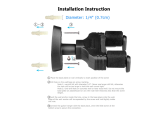
To mount the duct probe humidity element, refer to
Figure 5 and proceed as follows:
Housing
Conduit Hole
Snap-on Cover
Conduit Knockout
(Top and Bottom
of Cover)
Duct
Washer (Cupped Side
Toward Housing)
Conduit Fitting
(Not Provided)
Nut for Conduit Fitting
(Not Provided)
No. 8
Screw
(2)
Figure 5: Duct Probe Humidity Element
Assembly and Mounting
1. Remove any excess insulation from the duct that
prevents the probe from extending a minimum of
3 in. (76 mm) into the air stream.
2. Use the hole saw to make a 1 in. (25.4 mm) hole
in the duct for inserting the probe.
3. Pull the plastic cover off the housing.
4. Insert the probe into the duct, and use the housing
as a template to mark the location of the holes for
the mounting screws.
5. Remove the unit, and drill a 1/8 in. (3 mm) hole for
each mounting screw.
IMPORTANT: Remove the unit before drilling
to prevent any metal remnants from falling onto the
circuit board.
Seal any holes created during installation to help
reduce drafts and for more accurate humidity
readings.
6. Use a gasket, sealer, or other means to seal the
area around the 1 in. (25.4 mm) hole between the
unit and the duct.
7. Reinsert the probe, and secure the housing to the
duct using the two No. 8 screws provided.
Wiring
!
WARNING: Risk of Electric Shock.
Disconnect the power supply before making electrical
connections. Contact with components carrying
hazardous voltage can cause electric shock and may
result in severe personal injury or death.
AVERTISSEMENT : Risque de décharge
électrique. Débrancher l'alimentation avant de réaliser
tout branchement électrique. Tout contact avec des
composants conducteurs de tensions dangereuses
risque d'entraîner une décharge électrique et de
provoquer des blessures graves, voire mortelles.
Observe the following when wiring either type of
element:
• Do not run low voltage wiring in the same conduit
as line voltage wiring or other conductors that
supply highly inductive loads.
• Use 18 or 24 AWG wire.
• Make all wiring connections in accordance with the
National Electrical Code and all local regulations.
Wall Mount Humidity Element
To wire a wall mount model:
1. Connect the wires to the appropriate positions on
the terminal block. (See Figure 6.)
Terminal Block TB1
(Humidity Transmitter
Connection)
Terminal Block TB2
(Temperature Sensor
Connection)
Wiring
Opening
UP
UP
Sensor
Sensor
PWR
COM
OUT
Terminal
Wiring
Figure 6: Wiring the Wall Mount Humidity Element
2. Place the cover over the base, and tighten the
button-head screw (shown in Figure 3) on either
side of the unit to secure.
3. Choose the appropriate faceplate (vertical or
horizontal), depending on the mounting position of
the unit.
4. Remove the adhesive-backed paper from the
faceplate, and apply to the cover.

TRUERH Series HE-67xx Humidity Element with Temperature Sensor Installation Instructions 5
Duct Probe Humidity Element
To wire a duct probe model:
1. Route the wires from the controller to the unit
through the conduit hole in the housing.
IMPORTANT: If using a conduit fitting (not
provided), a washer is provided to support the fitting
in the housing. If the washer is not used, the fitting
could stress the plastic housing.
2. Break out the appropriate knockout from the cover
(shown in Figure 5) with pliers to accommodate
the wiring or conduit if used.
3. Connect the wires to the appropriate terminals of
the wiring block. (See Figure 7.)
Label
Output
Selection
0
-
5
V
0
-
1
0
V
P
W
R
C
O
M
O
U
T
T
E
M
P
T
E
M
P
Terminal
Designation
Input 18-30 VAC, 12-30 VDC
Ouput 0-5 or 0-10 VDC
DATE
PART NUMBER
Probe
Figure 7: Wiring the Duct Probe Humidity Element
4. Press the cover onto the base.
Troubleshooting
If the humidity element is not functioning properly:
1. Verify the unit is mounted in a location that is
indicative of space humidity and temperature
(away from drafts, moisture, sunlight, etc.).
2. Use a humidity tester with accuracy greater than
the element (±2% between 20 and 80% for
2% models; ±3% between 20 and 80% for
3% models), such as an optical dew point
hygrometer, to determine the percent of Relative
Humidity (RH).
Note: The humidity tester and the element must
sense the air at the same temperature. Before
testing, be sure to wait 30 to 60 minutes for
the tester to stabilize to ambient temperature
and humidity. A temperature difference of as
little as 1F° (0.6C°) can cause a difference in
measured RH of over 2.5% RH.
3. Calculate the percent of RH indicated by the
element as follows:
For 0 to 10 VDC output, multiply the output voltage
by 10. For example: 7.5 VDC x 10 = 75% RH
For 0 to 5 VDC output, multiply the output voltage
by 20. For example: 3.5 VDC x 20 = 70% RH
Note: ±0.9F° (±0.5C°) corresponds to an error of
about ±2% RH at 25°C if RH is at a high level,
e.g., 70%.
4. Compare the RH readings between the humidity
tester and the element. If the difference is more
than the sum of the allowable errors, replace the
element.
Ordering Information
Refer to Table 1 for accessories for the wall mount
humidity elements (none for the duct probe models),
and contact the nearest Johnson Controls
representative.
See Table 2 for product specifications for the humidity
elements.
Table 1: Accessories for the Wall Mount Humidity Elements
Product Code Number Description
GRD10A-608
Plastic Guard with Baseplate and Mounting Ring
T-4000-119 Allen-head Adjustment Tool (30/bag)
TE-1800-9600 Wall Plate Adaptor Kit required for wallbox mounting

6 TRUERH Series HE-67xx Humidity Element with Temperature Sensor Installation Instructions
Technical Data
Product
T
RUERH Series HE-67xx Humidity Element with Temperature Sensor
Power Requirements 14 to 30 VDC or 20 to 30 VAC at 50/60 Hz, Class 2
Current Draw
3 mA with no load, 25 mA maximum
Acceptable Wire Gauge 16 to 24 AWG wire (18 AWG wire recommended)
Humidity Element
at 77
°
F (25
°
C)
Signal: 0 to 5 VDC or 0 to 10 VDC, 1,000 ohm maximum load
Accuracy: HE-67x2: ±2% RH for 20 to 80% RH at 77°F (25°C)
±4% RH for 10 to 20% and 80 to 90% RH at 77°F (25°C)
HE-67x3: ±3% RH for 20 to 80% RH at 77°F (25°C)
±5% RH for 10 to 20% and 80 to 90% RH at 77°F (25°C)
Temperature Coefficient: -0.1 to 0.05% RH/°C at 5°C (41°F) to
-0.07 to -0.21% RH/°C at 65°C (149°F)
Temperature Sensors Thin-film Nickel: Accuracy: ±0.34°F (0.18°C) at 70°F (21°C)
Reference Resistance: 1,000 ohms at 70°F (21°C)
Resistance Change: Approximately 3 ohms/°F (5 ohms/°C)
Silicon: Accuracy: ±1°F (0.6°C) at 70°F (21°C)
Reference Resistance: 1,035 ohms at 77°F (25°C)
Resistance Change: Approximately 4 ohms/°F (8 ohms/°C)
Thin-film Platinum: Accuracy: ±0.65°F at 70°F (±0.36°C at 21°C)
Reference Resistance: 1,000 ohms at 32°F (0°C)
Resistance Change: Approximately 2 ohms/°F (4 ohms/°C)
Electrical Connections
3-position and 2-position screw terminal blocks
Ambient Operating
Conditions
32 to 140°F (0 to 60°C)
0 to 100% RH, 85°F (29.4°C) maximum dew point
Survival Operating
Conditions
-20 to 140°F (-29 to 60°C)
0 to 100% RH, 85°F (29.4°C) maximum dew point
Ambient Storage
Conditions
-40 to 140°F (-40 to 60°C)
0 to 100% RH, 85°F (29.4°C) maximum dew point
Materials Wall Mount: Beige plastic cover with metal base and metal foil face plates
Duct Probe: White plastic cover with dark gray plastic housing and probe
Dimensions Wall Mount (H x W x D): 1.81 x 2.12 x 3.12 in. (46 x 54 x 79 mm)
Duct Probe (H x W x D): 3.28 x 3.25 x 8.27 in. (83 x 83 x 210 mm)
Probe (L x D): 6.25 x 0.98 in. (159 x 25 mm)
Shipping Weight
0.6 lb (0.3 kg)
Agency Compliance
Duct Probe Material: 94-5V flammability rated per UL 94
The performance specifications are nominal and conform to acceptable industry standards. For application at conditions beyond these
specifications, consult the local Johnson Controls office. Johnson Controls, Inc. shall not be liable for damages resulting from misapplication or
misuse of its products.
European Single Point of Contact:
NA/SA Single Point of Contact:
APAC Single Point of Contact:
JOHNSON CONTROLS
WESTENDHOF 3
45143 ESSEN
GERMANY
JOHNSON CONTROLS
507 E MICHIGAN ST
MILWAUKEE WI 53202
USA
JOHNSON CONTROLS
C/O CONTROLS PRODUCT MANAGEMENT
NO. 22 BLOCK D NEW DISTRICT
WUXI JIANGSU PROVINCE 214142
CHINA

TRUERH Series HE-67xx Humidity Element with Temperature Sensor Installation Instructions 7
Building Efficiency
507 E. Michigan Street, Milwaukee, WI 53202
Metasys® and Johnson Controls® are registered trademarks of Johnson Controls, Inc.
All other marks herein are the marks of their respective owners. © 2016 Johnson Controls, Inc.
/