Page is loading ...

MULTI-FUNCTION JUMP STARTER
Model 92465
OPERATING INSTRUCTIONS
3491 Mission Oaks Blvd., Camarillo, CA 93011
Visit our Web site at: http://www.harborfreight.com
TO PREVENT SERIOUS INJURY,
READ AND UNDERSTAND ALL WARNINGS
AND INSTRUCTIONS BEFORE USE.
Copyright 2004 by Harbor Freight Tools
®
. All rights reserved. No portion of this
manual or any artwork contained herein may be reproduced in any shape or form
without the express written consent of Harbor Freight Tools.
For technical questions or replacement parts, please call 1-800-444-3353.
®
©

PRODUCT SPECIFICATIONS
SAVE THIS MANUAL
You will need this manual for the safety warnings and precautions, assembly, operating,
inspection, maintenance and cleaning procedures, parts list and assembly diagram.
Keep your invoice with this manual. Write the invoice number on the inside of the front
cover. Keep this manual and invoice in a safe and dry place for future reference.
GENERAL SAFETY RULES
IMPORTANT SAFETY INSTRUCTIONS
READ AND UNDERSTAND ALL INSTRUCTIONS
Failure to follow all instructions listed in the following
pages may result in electric shock, fire, and/or serious injury.
SAVE THESE INSTRUCTIONS
SKU 92465 For technical questions, please call 1-800-444-3353 PAGE 2
UNPACKING
When unpacking, check to make sure all the parts shown on the Product Features List-
ing on page 7 are included. If any parts are missing or broken, please call Harbor Freight
Tools at the number shown on the cover of this manual as soon as possible.
WARNING!
Item Description
Electrical Requirements Power Source: 12 VDC Sealed 17Ah Lead Acid Battery (Peak: 900 AMP).
Battery Charge Time: 20-24 Hours.
Battery Power Input: 120 VAC / 60 Hz Battery Charger.
12 VDC Cigarette Lighter Charger Adapter.
Battery Power Output: 120 VAC / 60 Hz.
12 VDC.
VDC/VAC Inverter Continuous Output Power: Up To 150 Watts.
VDC/VAC Inverter Fuse Size: 30 AMP.
Jump Starting Current: 400 AMP.
Jump Start Capability Jump Starts 10-30 Times With A Fully Charged Battery.
Air Hose Length 34”.
Tire Inflator Maximum PSI 260 PSI.
Additional Features 15 Watt Spotlight - Dual 6 Watt Fluorescent Lamps / Air Pressure Gauge.
12 VDC Hazard Flashing Light - Battery Charge/Overcharge Protection.
AC/DC Charger – Cigarette Lighter Adapter with 7 Ft. Cord.
Overall Dimensions 16-1/4” L x 8-3/8” W x 16-1/2” H.
Weight 24 Pounds.

3. Keep bystanders, children, and visitors away while operating power equip-
ment. Distractions can cause you to lose control. Protect others in the work
area.
PERSONAL SAFETY
1. Stay alert. Watch what you are doing, and use common sense when oper-
ating power equipment. Do not use power equipment while tired or under
the influence of drugs, alcohol, or medication. A moment of inattention while
operating power equipment may result in serious personal injury.
2. Dress properly. Do not wear loose clothing or jewelry. Contain long hair.
Keep your hair, clothing, and gloves away from moving parts. Loose
clothes, jewelry, or long hair can be caught in moving parts.
3. Avoid accidental starting. Make sure the Power Inverter Switch (3) of the
Jump Starter is in its “OFF” position before plugging a power tool into its
AC Output Socket (10). Plugging in with the Power Inverter Switch “ON” invites
accidents.
4. Do not overreach. Keep proper footing and balance at all times. Proper
footing and balance enables better control of the Jump Starter in unexpected
situations.
5. Use safety equipment. Always wear ANSI approved safety impact eye
goggles when using the Jump Starter. Always wear work gloves when using
this product.
TOOL USE AND CARE
2. Do not operate power equipment in explosive atmospheres, such as in the
presence of flammable liquids, gases, or dust. Power equipment creates
sparks which may ignite flammables.
1. Keep your work area clean and well lit. Cluttered benches and dark areas
invite accidents.
WORK AREA
SKU 92465 For technical questions, please call 1-800-444-3353 PAGE 3
1. Do not force the equipment. Use the correct equipment for your applica-
tion. The correct equipment will do the job better and safer at the rate for which
it is designed. Do not use small equipment, tools, or attachments to do the work
of larger industrial equipment, tools, or attachments. Do not use this product for
a purpose forwhich it was not intended.

2. Do not use the Jump Starter if any of the Control Panel components do not
work properly. Any equipment with a faulty Control Panel is dangerous and
must be replaced.
3. Before making any adjustments, changing accessories, or storing the Jump
Starter, make sure all Switches on its Control Panel are in their “OFF” posi-
tions. Such preventive safety measures reduce the risk of starting the equip-
ment accidentally.
4. Store idle equipment out of reach of children and other untrained persons.
Power equipment is dangerous in the hands of children and untrained users.
5. Maintain equipment with care. Do not use damaged equipment. Tag damaged
equipment “Do not use” until repaired. Never store the Jump Starter in a location
where this unit will be exposed to extreme heat or cold.
6. Check for misalignment or binding of moving parts, breakage of parts, and
any other condition that may affect the Jump Starter’s operation. If dam-
aged, have the Jump Starter serviced before using. Many accidents are
caused by poorly maintained equipment.
7. Use only accessories that are recommended by the manufacturer for your
model. Accessories that may be suitable for one Jump Starter may become
hazardous when used on another Jump Starter.
SERVICE
1. Equipment service must be performed only by qualified repair personnel.
Service or maintenance performed by unqualified personnel could result in a risk
of injury.
2. When servicing equipment, use only identical replacement parts. Follow
instructions in the
“Inspection, Maintenance, And Cleaning”
section of this
manual. Use of unauthorized parts or failure to follow maintenance instructions
may create a risk of electric shock or injury.
SKU 92465 For technical questions, please call 1-800-444-3353 PAGE 4
SPECIFIC SAFETY RULES
1. Maintain a safe working environment. Keep the work area well lit. Make sure
there is adequate surrounding workspace. Always keep the work area free of
obstructions, grease, oil, trash, and other debris. Do not use the Jump Starter in
areas near flammable chemicals, dusts, and vapors.
2. Maintain labels and nameplates on the Jump Starter. These carry important

information. If unreadable or missing, contact Harbor Freight Tools for a
replacement.
SKU 92465 For technical questions, please call 1-800-444-3353 PAGE 5
3. To avoid electrical shock, never start or run the Jump Starter in the rain.
Never allow water or other liquids to leak inside the Body or Light Lenses of
the Jump Starter.
4. Do not pull or carry the Jump Starter by its Jumper Cables or Air Hose, or
pull the Jumper Cables or Air Hose around sharp corners or edges. Keep
the Jumper Cables and Air Hose away from heated surfaces.
5. Avoid unintentional starting. Make sure you are prepared to begin work
before turning on any of the Switches on the Control Panel of the Jump Starter.
6. Do not stand on the Jump Starter. Standing on the Jump Starter may cause it
to tip, causing personal injury and/or product damage.
7. Never leave the Jump Starter unattended when any of its Switches on the
Control Panel are left in their “ON” position. Make sure all Switches are in
their “OFF” position before leaving.
8. Make sure to read and understand all instructions and safety
precautions as outlined in the manufacturer’s manual for the ve-
hicle/boat/etc. for which the Jump Starter will be used.
9. Never attempt to use the 120 volt AC Power Inverter setting on the Jump
Starter to start a vehicle/boat/etc. with a 12 volt DC system.
10. Make sure to turn off the vehicle/boat/etc. starter ignition before making
cable connections.
11. Never allow the Red and Black Battery Clamps to touch each other or the
same metal object.
12. Always connect the Red Battery Clamp of the Jump Starter to the positive
(+) terminal on the vehicle/boat/etc. battery.
13. Always connect the Black Battery Clamp of the Jump Starter to a clean
portion of grounded metal on the vehicle’s chassis (for negative grounded
systems).
14. When connecting the Battery Clamps to the terminals on the vehicle/boat/
etc., always connect the Red Battery Clamp first, then connect the Black
Battery Clamp. When disconnecting the Battery Clamps, always disconnect the
Black Battery Clamp first, then disconnect the Red Battery Clamp.

SKU 92465 For technical questions, please call 1-800-444-3353 PAGE 6
15. The Jump Starter setting is for emergency use only. Do not use the Jump
Start setting in the place of a vehicle/boat/etc. battery. Use the Jump Start set-
ting only to jump start a vehicle/boat/etc.
16. The Cigarette Lighter Adapter is for use with negative grounded 12V DC
systems only.
17. Avoid working alone. If an accident occurs, an assistant can bring help.
18. Avoid dangerous traffic. To avoid dangerous oncoming traffic, use the Jump
Starter as far away from the roadside as possible.
19. Do not block the Vents located on the sides of the Jump Starter. If the Vents
are blocked the internal Cooling Fan will not work properly, causing the Jump
Starter to overheat and automatically shut down.
20. WARNING! Lead acid batteries generate hydrogen gas during normal
operation, and even more gas is generated when the battery is charging. Hydro-
gen gas is explosive, poisonous to breathe, and highly flammable.
21. Always wear eye protection. When working on or around lead acid bat-
teries, always wear ANSI approved safety impact eye goggles.
22. Use the Jump Starter in a well ventilated area. Do not attempt to
jump start a vehicle/boat/etc. around flammable gases or liquids. If
necessary, wear an ANSI approved breathing respirator to avoid hydro-
gen gas fumes.
23. Proper Battery Care: Battery leakage may occur under extreme usage or tem-
perature conditions. If Battery fluid comes in contact with skin, wash with soap
and water and rinse with lemon juice and vinegar. If the fluid comes into contact
with the eyes, flush with water for several minutes and contact a doctor immedi-
ately. Never burn the Battery, as it can explode in a fire. Do not charge the Jump
Starter or a vehicle/boat/etc. with a leaking Battery. Contact local solid waste
authorities for instructions on correct disposal or recycling of the Battery.
24. Always re-charge the Battery when Jump Starter performance begins to
diminish. Severe heat is most destructive to the Battery. The more heat
generated, the faster the Battery loses power. A Battery that gets too hot can be
permanently damaged. Never over-discharge the Battery by using the Jump
Starter while its performance is decreasing. Never attempt to discharge the
Battery by continuing to use the Jump Starter. When Jump Starter perfor-
mance begins to diminish, turn off the Jump Starter, re-charge the Battery,
and use the fresh Battery for optimal performance.
25. Normal charging time for the Battery is 20-24 hours. Never charge the Battery
for over 24 hours. To insure safe operation, check periodically on the progress of
the battery charge. Never leave this product unattended for the full length of the
charge.

SKU 92465 For technical questions, please call 1-800-444-3353 PAGE 7
SAVE THESE INSTRUCTIONS
16
11
10
1. Battery Status Test Button
2. Single/Double Fluorescent
Lamp Switch
3. Power Inverter Switch
4. Compressor Switch
5. Spotlight Switch
6. Hazard Light Switch
7. Charging Jack
8. 12 VDC Input/Output Socket
9. Battery Status Indicator
10. Power Inverter Socket
11. 30 AMP Fuse
12. Charging Indicator
13. Hazard Light Bulb
14. Fluorescent Lamps
15. Spotlight Bulb
16. Air Pressure Gauge
17. Battery Clamp (Positive)
18. Battery Clamp (Negative)
19. Hose Compartment Door
20. Air Hose
21. Cable Compartment Door
22. Battery (Not Shown)
23. 12 VDC Cigarette Lighter
Adapter
24. AC/DC Charger
25. Hazard Light Lens
26. Fluorescent Lamp Lens
27. Spotlight Lens
PRODUCT FEATURES
26
25
21
18
17
15
14
13
12
9
8
7
27
6
54
3 2 1
23
24
FIGURE A
19
20
26. WARNING! People with pacemakers should consult their physician(s)
before using this product. Electromagnetic fields in close proximity to a heart
pacemaker could cause interference or failure of the pacemaker. In addition,
people with pacemakers should adhere to the following: Avoid operating power
equipment alone. Don’t use a power equipment with the power switch(s) locked
on. Properly maintain and inspect all power equipment before use to avoid elec-
trical shock.
27. WARNING! The warnings and precautions discussed in this manual can-
not cover all possible conditions and situations that may occur. It must be under-
stood by the operator that common sense and caution are factors which cannot
be built into this product, but must be supplied by the operator.

SKU 92465 For technical questions, please call 1-800-444-3353 PAGE 8
1. NOTE: The internal Battery (22) requires charging. The initial charge, and every
charge thereafter, requires 20 to 24 hours charge time.
2. Do not recharge the Battery (22) longer than 24 hours, as damage to the
Battery and/or AC/DC Charger (24) will occur. To insure safe operation, check
periodically on the progress of the battery charge. Never leave this product
unattended for the full length of the charge. (See Figure A,
page 7.)
3. Each 20 to 24 hours charge time enables the Jump Starter to jump start from 10
to 30 vehicles/boats having a 12 VDC system.
4. To charge the Battery (22), insert the Charging Plug of the AC/DC Charger (24)
into the Charging Jack (7) located on the Control Panel of the Jump Starter.
Then, plug the AC/DC Charger into a 120 volt, grounded, electrical outlet. In
approximately 20 to 24 hours, when the Battery (22) is fully charged, disconnect
the AC/DC Charger from its electrical outlet. Then disconnect the Charging Plug
of the AC/DC Charger from the Charging Jack on the Control Panel of the Jump
Starter. NOTE: The temperature of the Battery (22) and/or Charger (18) may
increase slightly during use and shortly after use, which is normal. The Battery
may not accept a full charge if it is charged immediately after use. Allow the
Battery to cool to room temperature before recharging for best results.
(See Figure A.)
5. Another way to charge the Battery (22) of the Jump Starter is to insert the Light-
er Plug of the 12 VDC Cigarette Lighter Adapter (23) into a 12 VDC outlet. Then,
insert the Charging Plug of the 12 VDC Cigarette Lighter Adapter into the Charg-
ing Jack (7) located on the Control Panel of the Jump Starter. (See Figure A.)
6. NOTE: At the beginning of every Battery (22) charge, the Charging Indicator
Light (12) will illuminate. The Charging Indicator Light will automatically turn off to
indicate when the Battery is fully charged. (See Figure A.)
7. NOTE: The Battery Status Test Button (1) operates the Battery Status Indicator
Lights (9) as follows: (See Figures A and B.)
8. WARNING! The user
should never attempt to
replace the Battery (22).
Battery replacement should
only be done by a qualified
service technician.
OPERATING INSTRUCTIONS
To Charge The Battery:
TOP GREEN LIGHT = FULLY CHARGED
GREEN LIGHT = 3/4 CHARGED
YELLOW LIGHT = 1/2 CHARGED
RED LIGHT = DISCHARGED
FIGURE B

SKU 92465 For technical questions, please call 1-800-444-3353 PAGE 9
To Jump Start A Vehicle/Boat:
1. WARNING! Make sure the electric system on the vehicle/boat is
12 volt DC.
2. Turn off the engine of the vehicle/boat that is to be jump started.
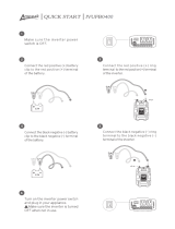
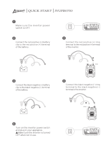
3. Attach the RED/POSITIVE (+) Battery Clamp (17) to the POSITIVE (+) terminal
on the vehicle/boat battery. (See Figure A.)
4. Attach the BLACK/NEGATIVE (--) Battery Clamp (18) to a clean portion of
grounded metal on the vehicle’s chassis (for negative grounded systems).
(See Figure A.)
5. Turn the vehicle/boat ignition switch to “START” for no more than 5 to 6 sec-
onds. NOTE: If the vehicle/boat engine
does not
start, turn the ignition switch to
“OFF” and wait at least 3 minutes before repeating this Step.
6. Once the vehicle/boat engine has started, disconnect the BLACK/NEGATIVE (--)
Battery Clamp (18) from the vehicle/boat battery and return the Battery Clamp to
its stored position on the Jump Starter unit. (See Figure A.)
7. Disconnect the RED/POSITIVE (+) Battery Clamp (17) from the vehicle/boat
battery and return the Battery Clamp to its stored position on the Jump Starter
unit. (See Figure A.)
8. As soon as possible, recharge the Jump Starter.
To Power 12 Volt DC Tools And Appliances:
1. The Jump Starter may also be used to power various 12 volt DC small power
tools and appliances (i.e., 12 volt DC drills, screwdrivers, cellphones, televisions).
2. To power a 12 volt DC power tool or appliance, insert the Charging Plug of the
Cigarette Lighter Adapter (23) into the power input socket of the tool or
appliance. Then, insert the Lighter Plug of the Cigarette Lighter Adapter into the
12 VDC Input/Output Socket (8) located on the front side of the Jump Starter.
(See Figure A.)
3. When finished using the 12 volt DC power tool or appliance, unplug the Lighter
Plug of the Cigarette Lighter Adapter (23) from the 12 VDC Input/Output Socket
(8). Then, unplug the Charging Plug of the Cigarette Lighter Adapter from the
power input socket of the tool or appliance. (See Figure A.)
4. As soon as possible, recharge the Jump Starter.

SKU 92465 For technical questions, please call 1-800-444-3353 PAGE 10
To Power A 120 Volt AC Tool Or Appliance:
1. The Jump Starter may also be used to power various 120 volt AC small power
tools and appliances with a rating of less than 150 Watts (i.e., 120 volt AC
drills, saws, phone systems, televisions, VCR’s, computers, pumps).
2. To power a 120 volt AC power tool or appliance, insert the Power Plug of the
tool or appliance into the Power Inverter Socket (10) located on the side of the
Jump Starter. Then, turn the Power Inverter Switch (3) to its “ON” position. The
Power Inverter Switch will illuminate, indicating the AC Output Socket is live.
(See Figure A.)
3. When finished using the 120 volt AC power tool or appliance, turn off the tool or
appliance and unplug its Power Plug from the Power Inverter Socket (10). Then,
turn the Power Inverter Switch (3) to its “OFF” position. The light in the Power
Inverter Switch will go out, indicating there is no power to the AC Output Socket.
(See Figure A.)
4. As soon as possible, recharge the Jump Starter.
To Operate The Air Compressor:
1. WARNING! The Air Compressor is capable of inflating an object up to
260 PSI. Do not overinflate an object. Prior to inflating, read and understand the
safety precautions, instructions, and recommended air pressure (PSI) as stated
in the manufacturer’s manual of the object you intend to inflate. Always wear
ANSI approved safety impact eye goggles when inflating tires and other
inflatables.
1. The Compressor Switch (4) operates the Air Compressor of the Jump Starter.
(See Figure A.)
2. Open the Hose Compartment Door (19) located on the side of the Jump Starter,
and pull out the Air Hose (20). (See Figure A.)
3. If inflating a tire, make sure the Lever of the Air Hose (2) is in its
vertical
position.
(See Figure C.)
FIGURE C
AIR HOSE LEVER
UNIVERSAL HOSE ADAPTER

SKU 92465 For technical questions, please call 1-800-444-3353 PAGE 11
4. Turn the Compressor Switch (4) to its “ON” position to turn on the Air Compres-
sor. (See Figure A.)
5. Remove the valve cap from the valve stem of the tire.
6. Attach the Universal Hose Adapter to the tire’s valve stem, with the Lever in the
vertica
l position. Make sure the Universal Hose Adapter is pressed down com-
pletely over the threads of the valve stem. (See Figures C and D.)
7. Once the Universal Hose Adapter is firmly in place, press the Lever down to its
horizontal position to lock onto the valve stem. Compressed air will begin to flow
from the Air Compressor into the tire. (See Figure D.)
8. Observe the Air Pressure Gauge (16) located on the side of the Jump Starter.
The Air Pressure Gauge is calibrated in PSI (Pounds Per Square Inch). When
the PSI indicated on the Air Pressure Gauge matches the recommended PSI of
the tire, turn the Compressor Switch (4) to its “OFF” position to shut off the Air
Compressor. Raise the Lever to disconnect the Universal Hose Adapter from the
tire’s valve stem. Then replace the valve cap onto the valve stem.
(See Figures C and D.)
9. Store the Air Hose (20) in its Hose Compartment, and close the Hose Compart-
ment Door (19). (See Figure A.)
10. If inflating a ball, air mattress, or other object, place the accessory Inflation
Nozzle or Air Nozzle into the Universal Hose Adapter and press the Lever down
to its
horizontal
position to lock the Nozzle in place. Then insert the Nozzle into
the air input hole in the object to be inflated. Never overinflate an object. Prior
to inflating, know the recommended air pressure (PSI) as stated in the
manufacturer’s manual of the object you intend to inflate. Overinflating an
object could result in the object exploding. (See Figure E, next page.)
11. Turn the Compressor Switch (4) to its “ON” position to turn on the Air Compres-
sor. Compressed air will begin to flow from the Air Compressor into the object
being inflated. (See Figure A.)
FIGURE D

SKU 92465 For technical questions, please call 1-800-444-3353 PAGE 12
12. Observe the Air Pressure Gauge (16) located on the side of the Jump Starter.
When the PSI indicated on the Air Pressure Gauge matches the recommended
PSI of the ball, air mattress, or other object, turn the Compressor Switch (4) to its
“OFF” position. Pull the accessory Inflation Nozzle or Air Nozzle out of the
air input hole in the inflated object. Raise the Lever to its
vertical
position and
remove the Nozzle from the Universal Hose Adapter. (See Figures C and E.)
13. Store the Air Hose (20) in its Hose Compartment, and close the Hose Compart-
ment Door (19). (See Figure A.)
FIGURE E
AIR
NOZZLE
INFLATION
NOZZLE
To Operate The Fluorescent Lamps:
1. The Single/Double Fluorescent Lamp Switch (2) controls the
two
Fluorescent
Lamps (14). The Lamp Switch features
three
positions: (1) “OFF”, ( 2) turns on
only one Lamp, (3) turns on both Lamps. (See Figure A.)
To Operate The Hazard Light:
1. The Hazard Light Switch (6) controls the Hazard Light Bulb (13). Turn the Haz-
ard Light Switch to its “ON” position to turn on the blinking Hazard Light. Turn
the Hazard Light Switch to its “OFF” position to turn off the Hazard Light.
(See Figure A.)
To Operate The Spotlight:
1. The Spotlight Switch (5) controls the Spotlight Bulb (15). Turn the Spotlight
Switch to its “ON” position to turn on the Spotlight. Turn the Spotlight Switch to
its “OFF” position to turn off the Spotlight. (See Figure A.)

SKU 92465 For technical questions, please call 1-800-444-3353 PAGE 13
Battery Clamp Reverse Polarity And Short Circuit Protection:
1. If the Battery Clamps (17, 18) are incorrectly connected to a vehicle/boat battery
with reverse polarity (i.e., negative (--) to positive (+) an internal Relay in the
Jump Starter will not connect the internal Battery (22) in the Jump Starter to the
Battery Clamps, therefore avoiding damaging currents. An internal Buzzer in
the Jump Starter will sound and the Battery Status Indicator (9) will flash to
alert the operator of the reversed polarity. The operator should then recon-
nect the Battery Clamps with the correct polarity to jump start the vehicle/boat.
(See Figure A.)
Over-Charge and Over-Discharge Protection:
1. When the Jump Starter is being recharged, the two Green Lights on the Battery
Status Indicator Lights (9) will eventually illuminate, indicating a fully charged
Battery (22). The internal overcharge protection circuitry in the Jump Starter will
prevent further charging, and the Charging Indicator Light (12) will automatically
go out. (See Figure A.)
2. When either the Fluorescent Lamps (14) or the Power Inverter Switch (3) are on,
over-discharge of the Battery (22) is prevented by the internal over-discharge
protection circuitry. When the Battery charge is low, the Fluorescent Lamps and
Power Inverter are automatically shut down and the Battery must be recharged.
When the Battery voltage drops to 10.6 volts, and internal audible alarm will
sound. (See Figure A.)
Power Inverter Overload Protection:
1. The Power Inverter Socket (10) will automatically shut off when overloaded.
The Power Inverter Socket will automatically reset when the overload condition is
corrected. The Power Inverter Socket will automatically shut off when a short
circuit in a tool or appliance is detected. Disconnect the tool or appliance and
have it serviced before reconnecting to the Power Inverter Socket. The Power
Inverter Socket will automatically shut off if there is insufficient ventilation of the
Jump Starter or if the temperature exceeds 150 Fahrenheit. An internal audible
alarm will also sound. Make sure the ventilation fan vents are not blocked, and
allow the unit to cool before restarting the Power Inverter. (See Figure A.)
0
JUMP STARTER PROTECTIVE FEATURES

SKU 92465 For technical questions, please call 1-800-444-3353 PAGE 14
INSPECTION, MAINTENANCE, AND CLEANING
1. WARNING! Before performing any inspection, maintenance, or cleaning
procedures, make sure all Switches on its Control Panel are in their “OFF” posi-
tions. Such preventive safety measures reduce the risk of starting the equipment
accidentally.
2. Before each use: Inspect the general condition of the Jump Starter. Check for
misalignment or binding of moving parts, cracked or broken parts, leaking Bat-
tery, damaged Hose, damaged electrical cables, and any other condition that may
affect its safe operation. If abnormal noise or vibration occurs, have the problem
corrected before further use. Do not use damaged equipment.
3. To replace the Hazard Light Bulb (13) and Fluorescent Lamps (14): To re-
place the Hazard Light Bulb, remove the Screw at the top of the Hazard Light
Lens (25). Carefully pull out and remove the Hazard Light Lens to expose the
Hazard Light Bulb. Push in and turn the Hazard Light Bulb to release it from its
Socket. Then pull out and remove the Hazard Light Bulb. Install a new Hazard
Light Bulb (not included). Then, replace the Hazard Light Lens and Screw.
To replace the Fluorescent Lamps, remove the Screw at the top of the Hazard
Light Lens (25). Carefully pull out and remove the Hazard Light Lens. Remove
the Screw at the bottom of the Fluorescent Lamp Lens. Carefully lift and pull out
to remove the Fluorescent Lamp Lens to expose the Fluorescent Lamps. Turn
the Fluorescent Lamps to release them from their Sockets. Then pull out and
remove the Fluorescent Lamps. Install the new Fluorescent Lamps (not in-
cluded). Replace the Fluorescent Lamp Lens and its Screw. Then, replace the
Hazard Light Lens and its Screw. (See Figure F.)
4. To replace the Spotlight Bulb (15): Unscrew and remove the Spotlight Lens
(27) to expose the Spotlight Bulb. Push in and turn the Spotlight Bulb to release
HAZARD
LIGHT LENS
(25)
SCREW
FLUORESCENT
LAMPS
(14)
SCREW
FLUORESCENT
LAMP LENS
(26)
HAZARD
LIGHT BULB
(13)
SPOTLIGHT
BULB
(15)
SPOTLIGHT
LENS
(27)
FIGURE F
REFLECTOR
BOWL

7. To clean: Clean the exterior of the Jump Starter thoroughly with a clean cloth,
water, and a mild detergent. Do not introduce any liquid into the interior of the
Jump Starter. Do not use solvents. Do not immerse any part of the Jump Starter
in liquids.
SKU 92465 For technical questions, please call 1-800-444-3353 PAGE 15
it from its Socket. Install a new Spotlight Bulb (not included). Then, replace the
Spotlight Lens. CAUTION! To avoid accidental electric shock, do not insert
fingers or hands behind the Reflector Bowl. (See Figure F.)
5. To replace the 30 AMP Inverter Fuse: Failure of the Power Inverter Socket (10)
to provide 120 volt power may be caused by a blown Fuse. Pull out and remove
the Fuse to check for a melted wire strand within the Fuse. If necessary, insert a
new 30 AMP Fuse into the Fuse Holder. (See Figure A.)
6. Battery precautions: Never burn Batteries, as they can explode in a fire. Do
not charge leaking Batteries. Only a qualified service technician should
perform maintenance or replace the Battery. Contact local solid waste au-
thorities for instructions on correct disposal or recycling of the Battery.
8. When storing: Store the Jump Starter in a safe, dry, location out of reach of
children and untrained users.
9. NOTE: The parts listed and shown in this manual are for illustration purposes
only, and are not available individually as replacement parts.
10. WARNING! All maintenance, service, and repairs not listed in this
manual are only to be attempted by a qualified technician.
PLEASE READ THE FOLLOWING CAREFULLY
THE MANUFACTURER AND/OR DISTRIBUTOR HAS PROVIDED THE PARTS LIST AND ASSEMBLY
DIAGRAM IN THIS MANUAL AS A REFERENCE TOOL ONLY. NEITHER THE MANUFACTURER OR
DISTRIBUTOR MAKES ANY REPRESENTATION OR WARRANTY OF ANY KIND TO THE BUYER THAT HE
OR SHE IS QUALIFIED TO MAKE ANY REPAIRS TO THE PRODUCT, OR THAT HE OR SHE IS QUALIFIED
TO REPLACE ANY PARTS OF THE PRODUCT. IN FACT, THE MANUFACTURER AND/OR DISTRIBUTOR
EXPRESSLY STATES THAT ALL REPAIRS AND PARTS REPLACEMENTS SHOULD BE UNDERTAKEN BY
CERTIFIED AND LICENSED TECHNICIANS, AND NOT BY THE BUYER. THE BUYER ASSUMES ALL
RISK AND LIABILITY ARISING OUT OF HIS OR HER REPAIRS TO THE ORIGINAL PRODUCT OR
REPLACEMENT PARTS THERETO, OR ARISING OUT OF HIS OR HER INSTALLATION OF REPLACEMENT
PARTS THERETO.
Note: No replacement parts are available.
/