Page is loading ...

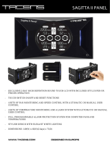
The figure below illustrates the system when the camera cover is pulled forward by loosening the camera cover
fixing screws.
Camera stand
Arm
Camera mount
Camera mounting bracket
Operation buttons (on right side face)
Camera cover
Camera cover fixing screws (×4)
Lens
Safety chain
Cable label
Connection cables
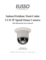
You can identify each connection cable by its shape and color.
1
2
3
4
5
6
7
8
9
10
11
1 / 153

Follow the steps below to connect each cable firmly to the one-touch connector.
Shape Color Signal Name Use
1
One-touch
connector
RED 24 VAC/12
VDC (+)
Used to connect the power supply.
WHITE 24 VAC/12
VDC (–)
2
Individual
cables
ORANGE ZOOM Used to adjust the camera zoom by external voltage control.
DC ± (6 to 12 V), +: WIDE/-: TELE
YELLOW FOCUS Used to adjust the camera focus by external voltage control.
DC ± (6 to 12 V), +: FAR/-: NEAR
GRAY/BLACK ALARM IN 1 Used to connect alarm switch, infrared sensor, or other external devices.
To automatically switch between the color and black/white modes, select
[DAY/NIGHT], choose the “COLOR” mode, and then set the “EXT ALARM” to
an appropriate input level.
BLACK ALARM IN 2
BLUE ALARM OUT Used to connect a buzzer, lamp, video recorder, or other peripheral device.
To control the alarm output externally from a remote location, on the ALARM
OUT screen, select [OUTPUT] and choose “REMOTE.”.
3
LAN cable
connector
BLACK (thick) COMMON Used to connect the LAN cable to enable network operations.
– N.C
BROWN/BLACK POE (–48V)
GREEN POE (0V)
SKYBLUE RX (–)
PINK RX (+)
ORANGE/BLACK TX (–)
GRAY TX (+)
4
BNC
connector
COAXIAL CABLE VIDEO OUT Used to connect to the VIDEO IN connector of your monitor.
For the cable type, see the “cable label” attached to the cable bundle.
2 / 153

Push the lever.
The terminal hole opens.
Insert the cable into the terminal hole.
Be sure to insert the cable firmly all the way to the end.
Release the lever.
The cable is now locked.
Make sure that the cable is locked firmly in place.
1
2
3
To prevent short-circuiting, make sure that the stripped wire portion is not exposed out of the
connector.
This connector is a separable type.
Separating the connector by pressing the connector lever facilitates your work, especially when
changing the connection with the power supply.
A
3 / 153

Be sure to turn OFF the power switch of all devices to be connected.
In addition, read the instruction manual for each device carefully so that you can connect devices correctly. Note
that incorrect connection may cause smoke or malfunction.
Connect the video cable.
Use the coaxial cable to connect the camera's video output (VIDEO OUT) connector to the video input (VIDEO
IN) connector of your monitor or other peripheral device.
Connect the power cables to the power terminals of the one-touch connector.
Use a power cable with an AWG wire (20, 21 or 22).
Although power wires have no polarity in this case, the earth wire must be connected to the earth (COMMON)
terminal.
1
Cable type RG-59U (3C-2V), 250 m maximum
Cable type RG-6U (5C-2V), 500 m maximum
Cable type RG-11U (7C-2V), 600 m maximum
Using lower-grade cables will cause the attenuation of the video and synchronization signals,
preventing correct transmission.
An RG-59U coaxial cable may be used if the distance between devices you want to connect is short.
However, avoid using it for piping or air wiring.
Use CCTV/Video-compatible coaxial cables.
2
4 / 153

Note the polarity (+/–) when you connect 12-VDC power cables.
Incorrect polarity may cause damage to your camera.
Plug in the power cable to the wall outlet.
When the camera is turned ON, the startup screen shows the system information (software version) on your
camera for approximately 10 seconds and then displays live video images.
While monitoring the video images displayed on the monitor, set the operating conditions and required functions
of the camera using the menu screen.
Connect a LAN cable to the LAN cable connector.
You can view the live video from the camera using Internet Explorer on your PC. When you want to view the live
videos from multiple cameras, install the supplied “VA-SW3050Lite” monitoring software on your PC.
Connect the following cables as required.
For detailed information on these connections, refer to the separate installation manual.
ALARM IN cables: GRAY/BLACK, BLACK
Used to connect alarm switch, infrared sensor, or other external devices.
ALARM OUT cable: BLUE
Used to connect a buzzer, lamp, digital video recorder, or other peripheral device.
FOCUS/ZOOM cable: YELLOW, ORANGE
Used to remote control the camera.
A voltage drop occurs depending on the thickness of the power wires. If you must use a long power
cable, determine the cable type by ensuring that the voltage at the power input terminal falls in the
operating range of this unit.
3
Since this camera supports PoE (Power over Ethernet), you can install the camera on a spot where
power supply is not available in the vicinity.
(For details, refer to the separate installation manual.)
Use a LAN cable no longer than 100 m (109.4 yds) with the shield type CAT5 or higher.
5 / 153

6 / 153

A surveillance system consists of mainly the following peripheral devices. Please use SANYO products for
connection with this camera.
Displays surveillance video for monitoring. The monitor also displays the menu screen.
Records surveillance video. For surveillance systems, the use of a DVR is recommended. DVRs ensure a long-
hour recording without video degradation.
7 / 153

The menu screen allows you to set the operating conditions and required functions of the camera according to
your installation environment or other needs.
Completely loosen the four fixing screws located on the front face of the camera and pull the camera cover
forward.
Now, you can use the operation buttons on the right side face of the camera to set the operating conditions of
the camera.
(For details, refer to the separate installation manual.)
Pressing the SET button for approximately three seconds causes the main menu to appear on the monitor.
buttons
Used to vertically move the cursor to select a menu item.
buttons
Used to make adjustments in horizontal direction or choose a setting value.
SET button
Use the SET button to set the value you adjusted or chose for the selected item, or switch to the sub-menu.
When the menu screen is not displayed, the operation buttons can be used to perform the following operations:
Focus adjustment
Use the button to set the focus to a near target.
After you complete setting up the camera, reinstall the camera cover in position and tighten the fixing
screws with a torque of 0.5 to 1 N·m (5 to 10 kgf·cm) to maintain the waterproof performance.
When the password lock is enabled, the user will be prompted for the entry of the password if he/she
attempts to access the setting on the menu screen.
Using this function, you can prevent users other than the password administrator from changing the
menu settings.
If you forget your password, contact the distributor from which you purchased the camera.
The menu screen will close automatically if no operation is performed for approximately 3 minutes.
1
2
3
1
8 / 153

Use the button to set the focus to a far target.
Zoom adjustment (Magnification: ×1 to ×30)
Use the button to zoom out of the target.
Use the button to zoom into the target.
One-push auto focus adjustment
Use the SET button to focus the camera automatically by one-push operation.
2
3
9 / 153

Main Menu Sub Menu Description of Setting
1
SYNC - Sets the signal synchronization method.
2
CAMERA IRIS Sets the lens iris.
WHITE BALANCE Adjusts the white balance of the video signal.
BLC Sets the backlight compensation function.
SHUTTER Sets the electronic shutter.
APERTURE Corrects the profile of the target object.
AGC Sets the gain of the video signal.
GAMMA Adjusts the contrast and brightness of the video signal.
MOTION Sets the motion sensor function that automatically detects moving targets.
POSITION Stores the zoom/focus settings of the current position by camera setting number (1 or
2).
DAY/NIGHT Sets the Day/Night function that automatically switches between color and black/white
video modes depending on the luminance of the target.
3
LENS FOCUS Sets the focusing mode.
ZOOM Sets the optical zooming speed and electronic zooming option.
4
ALARM ALARM IN Provides alarm input settings.
ALARM OUT Provides alarm output settings.
ALARM DISPLAY Sets the alarm display function.
5
PRIVACY MASK MASK 1 to 4 Masks anywhere you want to hide on the screen for the purpose of privacy protection.
6
PASSWORD PASSWORD LOCK Sets the password lock function that prevents access to the menu screen.
PASSWORD
CHANGE
Changes the password.
7
LANGUAGE - Sets the language in which menu items are displayed on the menu screen.
8
OPTION DISPLAY Sets the information to be displayed on the monitor.
MIRROR Sets the mirroring function that electronically reverses the displayed image.
STABILIZER Corrects the image from the camera when it sways.
NETWORK Sets the communication conditions for network connection.
10 / 153

While viewing the menu screen on the monitor, set the operating conditions using the operation buttons on the
camera.
Use the / button to select the menu item.
If the “
↓ ”
(down arrow ) symbol is shown to the right of the selected menu item, press the SET
button.
The next-level sub menu or the details setting screen appears.
To choose a setting, show the desired value or option using the / button.
To return to the previous screen, use the / button to select [MENU] and, with the setting of
“BACK” shown, press the SET button.
To close the menu screen, use the / button to select [MENU], use the / button to change
1
2
3
4
5
11 / 153

the setting from “BACK” to “END”, and press the SET button.
The main menu disappears and live video images appear on the screen.
To display the main menu again, press the SET button located on the side face of the camera for approximately
three seconds.
12 / 153

Use the / button to select [PRESET] on the main menu, use the / button to choose “ON”, and press
the SET button.
This initializes all the menu settings, with the value for [PRESET] returned to “OFF”.
Performing the above resetting operation on a sub menu resets the settings on lower-level screens
to the defaults.
Note that the resetting operation does not reset the settings for the following items:
[PRIVACY MASK] on main menu
[PASSWORD] on the main menu
[DISPLAY (TITLE)] and [NETWORK] on the OPTION menu
Zoom or focus setting in [POSITION] on the CAMERA menu
Note that the value of the item [POSITION] is reset from “ON” to the default “OFF”.
When the [POSITION] setting is switched to “OFF”, the zoom and focus settings stored in the
camera will be overwritten by those settings of the current position.
In the same way, performing zoom or focus operation with [POSITION] set to “OFF” also
overwrites the stored zoom and focus settings.
13 / 153

This camera supports the following synchronization methods:
INT: Internal synchronization
Performs synchronization according to the camera’s internal signal.
L-L (Line Lock): Power source synchronization
Performs synchronization according to the frequency of the commercial power source. With this method,
you can manually adjust the vertical synchronization phase.
14 / 153

Use the / button to select [SYNC], use the / button to choose “L-L”, and press the SET
button.
The L-L SETTING screen appears.
Use the / button to adjust the vertical synchronization phase.
Select [MENU] and choose “BACK” or “END” to complete adjustment.
1
2
3
15 / 153

On this screen, set the operating conditions of the camera.
You can have two patterns of operating conditions and use the preferable condition pattern for your environment
by choosing the camera setting number (1 or 2).
IRIS setting
Sets the lens iris.
WHITE BALANCE setting
Sets the white balance.
BLC setting
Sets the backlight compensation function.
SHUTTER setting
Sets the electronic shutter.
APERTURE setting
Corrects the profile of the target object.
AGC setting
Sets the gain of the video signal.
GAMMA setting
Adjusts the contrast and brightness of the video signal.
MOTION setting
Sets the motion sensor function that automatically detects moving targets.
POSITION setting
Stores the zoom/focus settings of the current position by camera setting number (1 or 2).
DAY/NIGHT setting
Sets the Day/Night function that automatically switches between color and black/white video modes
depending on the luminance of the target.
Setting example for using the operating conditions for the daytime use and nighttime use:
Select [CAMERA], choose the setting number “1”, and set the operating conditions for daytime
use.
Return to the main menu, select [CAMERA], choose the setting number “2”, and set the operating
conditions for nighttime use.
To switch between these operating conditions, select [CAMERA] in the main menu and choose
“1” (for daytime use) or “2” (for nighttime use) as the camera number.
(You may use alarm input to switch the operating conditions.)
1
2
3
16 / 153

Use the / button to select [CAMERA] on the main menu, use the / button to choose the
camera setting number (“1” or “2”) with which you want to set operating conditions, and press
the SET button.
The CAMERA setting screen for the chosen camera setting number appears.
1
17 / 153

Use this setting to set the lens iris (auto or manual) according to the luminance level of the target objects.
AUTO: Auto iris
MANU: Manual iris
Automatically adjusting the lens iris enables the reproduction of natural images even in outdoors where the
luminance difference is large, or under backlight conditions.
Use the / button to select [IRIS], use the / button to choose “AUTO”, and press the SET
button.
The IRIS SETTING screen appears.
Use the / button to select [SENSE UP] and use the / button to choose the electronic
sensitivity boosting power.
Available settings: OFF, x2, x4, x8, x16, x32
Use the / button to select [LEVEL] and use the / button to adjust the level of the video
signal level.
Available settings: 0 (dark) to 100 (bright)
Select [MENU] and choose “BACK” or “END” to complete adjustment.
The auto iris function is not available when the electronic iris (EI) is set. Set the lens iris manually using the
following procedure.
Use the / button to select [IRIS], use the / button to choose “MANU”, and press the SET
1
2
If the electronic sensitivity boosting power cannot be set:
[MOTION] is set to “ON”, or [AGC] is set to “OFF”.
Setting the electronic sensitivity boosting power causes the following:
The CCD exposure time will be increased automatically in dark situations. This may result in
conspicuous afterimages, blurs, and white spots in moving target objects.
The [SHUTTER] (electronic shutter) setting (“SHORT” or “LONG”) and the [V-RESO UP] (vertical
resolution increase) setting will be cancelled.
The [EI] (electronic iris) setting will be cancelled.
When [DAY/NIGHT] is set to “AUTO”, [SENSE UP] works only for black/white video images.
3
4
1
18 / 153

button.
The IRIS SETTING screen appears.
Use the / button to select [EI] and use the / button to choose “ON”.
The electronic iris is now enabled, controlling both the AGC circuit and the shutter speed to adjust the exposure.
Use the / button to select [IRIS STOP] and use the / button to adjust the iris stop.
The lens iris changes based on the iris stop setting.
Available settings: 1 (closes the iris = dark) to 17 (opens the iris = bright)
Use the / button to select [LEVEL] and use the / button to adjust the level of the video
signal level.
Available settings: 0 (dark) to 100 (bright)
Select [MENU] and choose “BACK” or “END” to complete adjustment.
2
Setting the electronic iris (EI) causes the following:
The [SHUTTER] (electronic shutter) setting (“SHORT” or “LONG”) will be cancelled and the
[SENSE UP] (electronic sensitivity boosting) will not work.
Under extremely bright lighting, the electronic iris cannot adjust the light entering through the lens,
resulting in a phenomenon such as a smear. This may be prevented by changing the lighting angle
or other measures.
Under fluorescent lighting, the camera may cause the target images to flicker. To prevent this,
replace the fluorescent lamps with incandescent lamps.
3
4
5
19 / 153

Use this setting to set the white balance according to the installation conditions of the camera.
ATW: Auto trace white balance
AWC: Push-lock auto white balance
3200: Fixed white balance (for indoors)
5600: Fixed white balance (for outdoors)
FLUO: Fixed white balance (for fluorescent lighting)
MWB: Manual white balance
Auto trace white balance (ATW) automatically adjusts the white balance to provide optimal colors, even if the
light source for the target objects is changed.
Use the / button to select [WHITE BALANCE], use the / button to choose “ATW”, and
press the SET button.
The ATW SETTING screen appears.
Select [MENU] and choose “BACK” or “END” to complete the setting.
To mask a specific light source, or to set the SMART ATW function, do the following.
If the target objects include an extremely bright light source, set a mask as follows to correct the white balance.
Use the / button to select [MASKING], use the / button to choose “ON”, and press the
SET button.
The ATW MASKING screen appears, with a blinking mask pattern shown at the top left.
Use the buttons to move the mask pattern over the light source you want to mask and
press the SET button.
This sets a mask at the position where you moved the mask pattern. A new mask pattern starts blinking.
1
2
1
2
20 / 153
/