1
SUZUKI
LED TV SERVICE MANUAL
Model Name:
Version NO : 1.0
The release of this document is under controlled by the company. Any extra
copy of this document must be written permission by the product manager.
SZTV-40LED6A

2
TABLE OF CONTENTS
RECORDS OF REVISION …………………………………………………………………………..…..03
CHAPTER 01: WARNING……………………………………………………………………………04
CHAPTER 02: SAFETY PRECAUTIONS…………………………………………………………..05
CHAPTER 03: PRODUCT ROUGH SPEC……………………...…………………………………..07
CHAPTER 04: MAIN COMPONENT DIAGRAM………………………………………….……..07~11
CHAPTER 05: EASY TROUBLE SHOOTING…………………………………………………11~15
CHAPTER 06: TOOUBLE SHOOTING FLOW CHART………………………………………16~21
CHAPTER 07: MAIN BOARD SCHEMATICS…………………………………………………21~34
CHAPTER8 : PWERT BOARD SCHEMATICS………………………………………………….34~35
CHAPTER9 : FIRMWARE UPDATE SOP…………………………………………………………36-39

3
RECORDS OF REVISION
Revision No. Revision Date
Page Reason Description
V1.0 2012.11.30 All Initial Release

4
CHAPTER 1: WARNING
This service information is designed for experienced repair technicians only and is
notdesigned for user by the general public.It does not contain warnings or cautions to
advise non-technical individuals of potential dangers in attempting to service a
product.Products powered by electricity should be serviced or repaired only by
experienced professional technicians.Any attempt to service or repair the product or
products dealt within this service information by anyone else could result in serious
injury or death.

5
CHAPTER 2: SAFETY PRECAUTIONS
2-1. CAUTION:
No modification of any circuit should be attempted. Service worker should only be performed after going
through to familiar with all of the following safety checks and servicing guidelines.
2-2. SAFETY CHECK
Care should be taken while servicing this TV display. Because of the high voltage is used in the inverter
circuit. These voltages are exposed in such areas as the associated transformer circuits.
2-3. POWER SUPPLY REQUIREMENTS
The internal power converter with the attached AC power cord is necessary for the TV monitor. Any attempt to
replace another power converter could result in serious of problems on the display.
2-4. LEAKAGE CURRENT HOT CHECK
2-4-1 Plug the AC cord directly into the AC outlet. Do not use an isolation transformer during this check.
2-4-2 Connect a 1500 ohm, 10 watt resistor, paralleled by a 0.15uF capacitor between each metallic part and a
good earth ground.
2-4-3 Use an AC voltmeter with 1000 ohm / volt or more sensitivity and measure the AC voltage across the
combination 1500 ohm resistor and 0.15uF capacitor.
2-4-4 Move the resistor connection to each exposed metallic part and measure the voltage.
2-4-5 Reverse the polarity of the AC plug in the AC outlet and repeat the above measurement.
2-4-6 Voltage measured must not exceed 1.5 volt RMS, from any exposed metallic part to the ground.
A leakage current tester may be used in the above hot check, in which case any circuit measured
must not exceed 1 milliamp. In the case of a measurement exceeding the 1 milliamp value, the rework is
required to eliminate the chance of a shock hazard.
To Metal Parts
V
AC VOLTMETER
1500 10W
0.15u
.
Earth Ground

6
CHAPTER 3: PRODUCT ROUGH SPEC
Product Rough Specification
TV ID YC CA1
Pnael Model V390HJ-P02
Main Board Model TP.VST59.P83A
Power model NC
Power Consumption(Stand-by Mode) <0.5W
Power Consumption(MAX) 45W
Power Input Voltage 110-240V~
General
Information
Power Rated Input Freq 50/60Hz±5%
Video System PAL ;SECAM
Sound System BG;DK,I,L/L' ;NICAM/A2
Max Storage Channel 199CH
ATV
Teletext 1000Page
Modulation NA
Video System NA
Sound System NA
Basic Functions NA
Max Storage Channel NA
DTV
Teletext NA
COMB Filter 3D
Deinterlace 3D
Audio power output 2 X 8W@8ohm THD+N<10%@1KHz
Audio Frequency Response 100Hz~15KHz
OSD Language Eng;Fre; Gen,Ita,Rus,Put
Other
Parameter
Panel Resolution Up to 1920*1080
AV Input 1
S-Video Input NO
SCART Input 1
CI (Common Interface) NO
Component(Y Pb Pr or Y Cb Cr) 1
VGA D-15 Input 1
PC Audio L/R Input 1
HDMI Input 3
Head phone out 1
AV out NO
SPDIF NO
Terminals
DVD & Driver board NO
EMC EN 55022 Class B Yes
Safety EN 60950 (Europe) Yes
ESD spec. 4 / 8 KV (Reference)
Operation Temperature 0~40'C(Operating), -20~60'C(Storage)
Environmental
Conditions
Relative Humidity 10~85%(Operating) 5~95%(Storage)

7
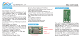
CHAPTER 4: MAIN BOARD CONNECTION
5-1: Main Board TOP View
5-2: Main Board Botton View
5-3: Main Board Connection

8

9

10

11
CHAPTER 5: EASY TROUBLE SHOOTING
7.1 Troubleshooting for Common Use
Note: Before opening the cabinet and working on the repairs, please read the troubleshooting and Q&A
attached in theuser’s manual, which has covered most of the problems caused by unproper using or settings to
the TV set. If that does notwork, please carry out the easy troubleshooting before checking or replacing the main
parts of the television. The
troubleshooting guides given below base on the situation in which the TV’s functions are set and used
properly.Plus, if the easy troubleshooting can not help, please work on the repairing according to the procedures
given in chapter 5,Exception Handles.Check the connection and condition of wires and inlets that relate to power
board, including the AC power inlet, the power incoming wire, wires between power board and mainboard, etc.
TV can not be turned on
Check the diagram arround power board to see If there exists a short circuit or creepage.
Check the sleep timer setting.
Auto turning off
Check the surrounding diagram of power board. The problem is most possibly caused by short circuit or wire
breakage,
because this kind of malfunctions can cause excessive current, which will make the power board startup
self-protection.
If the TV screen can not display after the blink, that means the panel or other parts of equipment is broken (most
likely by
unproper input voltage). Ensure the input voltage of every component, and then check the part that is suspected
damaged.
The screen goes black after a shorting blink
If the panel can work normally at the other time, it may be caused by bad mainboard. Upgrade to the latest
software first,
if that does not work, attempt to change the mainboard.
There exists afterimages after power off
If this problem occurs repeatedly, check the surrounding diagram and connections of panel inverter board. Also,
the
blacklight unit and LCD lamps should be checked out.IListen to the squeak carefully to make sure where the noise
comes from. If it is from speakers, the voice may be caused by bad speakers. Change them for a try..
There exists squeak when TV is working
If the noise comes from the inner parts of cabinet, it may be produced by abnormal AC current in power board.
Change the
board and check its surrounding circuits for a try.Check the routing of wires inside the cabinet to suppress
interference.
The power board may be bad. Please change the board for testing. If it cannot help, refer to the chapter 5 for more
intensive information.In addition, the malfunction of LCD panel can cause failure of power on. Please refer to 4.2
Troubleshooting for Displayingfor more information.
7.2 Troubleshooting for Displaying
Check the power board output and main board input ports to make sure whether the TV has been turned on
successfully,

12
because the failure in power on can lead to a no-display problem.
No display (including white screen, black screen, etc.)
Note: If the troubleshooting given below can not help you, change the LCD panel for a try. But we strongly suggest
you
regard changing the panel as the last step of fixing the display problem.
If it is proved to have been electrified and turn on, check the LVDS cable first.
Check if both of the two plugs of the flat cable between mainboard and power board have been well inserted into
the slots.
Unstable power supply can also cause serious display problem.
If the display problem only happens in one input mode, that may be caused by wrong version software. Update the
new
software. If that can’t help, change the main board for a try.
Bad LVDS cable and inappropriate panel driving voltage is still the biggest factor of this problem. So check them
first.
Screen tearing, or there exists moire on screen
If the cable and voltage are correct, update the software for a try.Sometimes the fastening pieces can make
unproper pressure to LCD panel, check them out.Refer to chapter 5 for more details and resolution ways.Refer to
chapter 5 for more details and resolution ways.If the screen tearing happens in one or several input sources while
the other source can display normally, it can be caused by bad mainboard most likely. Please change the
mainboard for a try.If the bad line is very narrow, it is usually caused by LCD panel malfunction, change the panel
for a try.
Straight dark/light line(s) on screen
If the lines link together and become a bad band, upgrade the software and then check the ports abd circuits of
brokendownoutput mode(s).If the dark/light line ,or band, apprears in all the input modes, please change the LCD
panel. But we suggest you check the panel inlet board(which links the panel and mainboard though LVDS cable)
first, because sometimes the liquid crystal displaying unit is okay, while the inlet board has a transmitting problem,
which also will lead to a displaying failure. If the cast or interference happens in only one input mode, check the
output port(on mainboard) and transmitting network (arround mainboard) of that mode.
Color cast or interference
If the cast or interference happens in all the input modes, please exclude the malfunction according to easy
troubleshooting for No Display. If that can not help, refer to chapter 5 for more details and resolution ways. In
addtion, most of this kind of problems come from the bad mainboards.
Chapter 4 Easy Troubleshooting
7.3 Troubleshooting for Audio
Check whether the speakers are broken first.
No Sound
Note: Comparing with the display problem, the audio malfunctions are easier to work out. Constantly, if you have
excluded
the possibility of bad speakers and bad connection of audio output, the problem generally comes from the audio
processing parts of mainboard. Please change mainboard for a try, or refer to chapter 5 for further information
about repairing. Check the wire that links the mainboard and speakers. Watch if there is fracture or cladding
material breakage.
Check the joint of speakers and audio wire, watch if there is poor soldering or fake solder. Besides, the polarity
mistake

13
can also lead to audio problem.
7.4 Troubleshooting for Keyboard
Check the wire between mainboard and keyborad, watch if there is fracture or cladding material breakage.
No key can work
Check the joint of mainboard and keyboard wire, watch if there is poor soldering ofrfake solder.
Check the resistances that locate on the keyboard PCB. Watch if there is wrong or broken ones. Also, the poor
soldering of fake solder should be concerned and checked carefully.
Check the other components of keyboard(such as capacitances and microswithes) are wrong or bad. Check
whether there is a jam at the sound hole in front cabinet.
Volume too low
Check whether one or more speakers are bad.
Check whether the audio wires are installed reversedly. The left channel wire should be white and the right
channel wire
is red.
Sound channel loss or confounding
If the connection is stable and right, the mainboard audio output module may be bad, refer to chapter 5 for more
details
and resolution ways.
Check the audio output socket of mainboard to see whether it is wrongly inserted. If not, the mainboard audio
output module may be bad, refer to chapter 5 for more details and resolution ways.
Check if there is anything should not exist in the speaker hollow space (such as screws).
Noise
Check if the speakers are bad.
Check if the antihunting EVA is broken or missing.
Check the screws that fasten the keyboard to the cabinet. They may be lost or getting loose.
Keys are sunken
The key set may be bad, change them.
7.5 Troubleshooting for Remote Control
Check the wire between mainboard and RC board, watch if there is fracture or cladding material breakage.
The RC (remote control, the same below) does not work
Note: If the troubleshooting can not help, please change the RC board. If that still can’t solve the problem, please
refer to
chapter 5 for more details and resolution ways with a will to mainboard repairing.
Check the joint of mainboard and RC board wire, watch if there is poor soldering or fake solder. Also, the short
circuit
can lead to this problem, too.
Check the infrared senser that locates on the keyboard PCB. Watch if it is wrong or broken. Also, the poor
soldering of
fake solder should be concerned and checked carefully.
The short circuit is the most probable causation factor of this proble. Check the wire and joints for a judgement.
The LED displays light in wrong color
Check the cable that links mainboard and RC board, watch if it is inserted with wrong location(similar with

14
left-right channel
wire fault for audio).
Check the LED assembling, watch if its pins are in wrong location.
Check the other components of RC board are wrong or bad.That is usually caused by bad keyboard, change it for
a try.
There is a reacting delay when operating the keys
Check the keyboard to see whether there is a short circuit between each soldering joint.
Functions of keys are out of order
If a key is supposed to be able to achieve more than one functions, but it can achieve not all of them, that is
usually
caused by wrong software. Please update the latest and correct software for a try.
If you can’t ensure where the problem comes from, change the keyboard for a try. If that still can’t help, refer to
chapter 5
for more details and resolution ways.
Check all the resistances on PCB board.

15
CHAPTER 6: TROUBLE SHOOTING FLOW CHART

16

17

18

19

20
CHAPTER 7: MAIN BOARD&POWER SCHEMATICS
Page is loading ...
Page is loading ...
Page is loading ...
Page is loading ...
Page is loading ...
Page is loading ...
Page is loading ...
Page is loading ...
Page is loading ...
Page is loading ...
Page is loading ...
Page is loading ...
/