
PD-IM-7508 Evaluation Board - User Guide
PD-IM-7508
Evaluation Board User Guide
Including:
PD69108 – PoE Manager
PD39100 – PoE Controller
Security Status: Restricted
PRODUCTION DATA: Information contained in this document is proprietary to Microsemi and is current as of
publication date. This document may not be modified in any way without the express written consent of Microsemi.
Product processing does not necessarily include testing of all parameters. Microsemi reserves the right to change
the configuration and performance of the product and to discontinue product at any time.

PD-IM-7508 Evaluation Board - User Guide
Copyright © 2013
Microsemi
2
Rev 0.1 / 04 Aug 2013 Analog Mixed Signal Group
1 Enterprise, Aliso Viejo, CA 92656, USA; Phone (USA): (800) 713-4113, (ROW): (949) 221-7100 Fax: (949) 756-0308
Reference Documents
IEEE 802.3af-2003 Standard, DTE Power via MDI
IEEE802.3at-2009 Standard, DTE Power via MDI
PD69108 datasheet, catalog number DS_PD69108
PD39100 datasheet, catalog number DS_PD39100
PD70200 datasheet, catalog number DS_PD70100_PD70200
Application note 206: Designing an 8-port with PD39100 & PD69108 (802.3af/802.3at
Compliant), catalog number PD39100_PD69108_AN206
Application note 186: Layout Design Guidelines for PD69108/PD69104 PoE Systems,
catalog number 06-0081-080
PD63000/G & PD69000 & PD69100 Serial Communication Protocol User Guide , catalog
number PD63000_UG
Software GUI user guide catalog number 06-0027-056
The above documents can be obtained via Microsemi customer support. To access other documents, go to our
website at http://www.microsemi.com/, and under Tech Support\Documentation look up the relevant documents.

PD-IM-7508 Evaluation Board - User Guide
Copyright © 2013
Microsemi
3
Rev 0.1 / 04 Aug 2013 Analog Mixed Signal Group
1 Enterprise, Aliso Viejo, CA 92656, USA; Phone (USA): (800) 713-4113, (ROW): (949) 221-7100 Fax: (949) 756-0308
Table of Contents
1
About this Guide ................................................................................................................................... 4
1.1
Objectives .................................................................................................................................... 4
1.2
Audience ...................................................................................................................................... 4
1.3
Organization ................................................................................................................................. 4
2
Introduction ........................................................................................................................................... 5
2.1
Hardware Block Diagram Description .......................................................................................... 6
2.2
Evaluation Board/System Ordering Information .......................................................................... 6
2.3
Evaluation System Features ........................................................................................................ 6
2.4
Evaluation System Interfaces & Connections .............................................................................. 7
3
Physical Description ............................................................................................................................. 8
3.1
Switches ....................................................................................................................................... 8
3.1.1
Reset Button ........................................................................................................................... 8
3.1.2
Power Good Dip Switch .......................................................................................................... 8
3.2
Connectors ................................................................................................................................... 8
3.2.1
Connectors Table ................................................................................................................... 8
3.2.2
Connectors Detailed Explanation ........................................................................................... 9
3.3
Led Indications ........................................................................................................................... 12
4
Electrical Characteristics .................................................................................................................... 13
5
Installation ........................................................................................................................................... 14

PD-IM-7508 Evaluation Board - User Guide
Copyright © 2013
Microsemi
4
Rev 0.1 / 04 Aug 2013 Analog Mixed Signal Group
1 Enterprise, Aliso Viejo, CA 92656, USA; Phone (USA): (800) 713-4113, (ROW): (949) 221-7100 Fax: (949) 756-0308
1 About this Guide
1.1 Objectives
This user guide provides both a description and operation procedures for Microsemi's PD-IM-7508 evaluation
system. This system is used to evaluate the performance of 8 port PoE applications.
1.2 Audience
This user guide is intended for qualified personnel, meaning operators and technicians who have a background in
basic electronics.
1.3 Organization
This guide is divided into several sections:
Chapter
1
“About this Guide” which describes the objectives, audience and organization.
Chapter
2
“Introduction” which gives an overview of the main functions, features, physical characteristics,
and ordering information.
Chapter
3
“Physical Description” which provides a physical description of the components (switches,
jumpers, connectors).
Chapter
4
“Electrical Characteristics” which lists the electrical characteristics of the PoE evaluation
system.
Chapter
5
“Installation” which describes the installation process.

PD-IM-7508 Evaluation Board - User Guide
Copyright © 2013
Microsemi
5
Rev 0.1 / 04 Aug 2013 Analog Mixed Signal Group
1 Enterprise, Aliso Viejo, CA 92656, USA; Phone (USA): (800) 713-4113, (ROW): (949) 221-7100 Fax: (949) 756-0308
2 Introduction
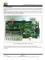
Microsemi’s Evaluation Board PD-IM-7508 provides the designer with the environment to evaluate the performance
and the implementation of 8-port Power over Ethernet (PoE), based on Microsemi’s PoE Devices (PD39100 &
PD69108).
Evaluation Board assists Switch designers to evaluate an IEEE- 802.3af-2003 and IEEE802.3at-2009PoE based
solution, with maximum flexibility and ease in configuration.
Microsemi’s PD69108 is a 8-port, mix-signal, high-voltage Power over Ethernet (PoE) Manager designed to support
IEEE- 802.3af-2003 and IEEE802.3at-2009 PoE applications.
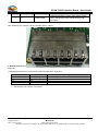
Figure 1: PD-IM-7508 Evaluation Board – General View
This document details the steps and connection instructions required to install and operate this board.
Evaluation Board enables PoE designers to evaluate Microsemi's PoE solution with maximum flexibility and ease in
configuration.
Front-end circuit
ESPI
Isolation
PoE controller
PD69108 circuit
UART
44-57V
Input
PoE input
PD70200 circuit
Power Bank
Selection

PD-IM-7508 Evaluation Board - User Guide
Copyright © 2013
Microsemi
6
Rev 0.1 / 04 Aug 2013 Analog Mixed Signal Group
1 Enterprise, Aliso Viejo, CA 92656, USA; Phone (USA): (800) 713-4113, (ROW): (949) 221-7100 Fax: (949) 756-0308
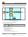
2.1 Hardware Block Diagram Description
The block diagram shown in Figure 2 illustrates the 8-port Evaluation Board. A single PD39100 microcontroller unit
(PoE Controller) is connected to a single PD69108 PoE device. As shown in the figure, the PoE Controller controls
and monitors the PoE device using an isolated ESPI bus. Communication with PoE controller is done by a serial
communication interface (UART by USB). EVB can be powerd by an external power supply or by another 4pairs
PSE port.
Host
Serial
Comm
Peripherals,
LEDs
DC in via J1
Connector
PoE Controller
PD39100
/DC DC
Converter
Channels 0-7
ESPI
Isolation
PD69108
ESPI BUS
Isolated
ESPI BUS
DC in via PoE
Port – CON1
PD70200 PD70200
Figure 2: System Configuration
2.2 Evaluation Board/System Ordering Information
The following table lists EVB ordering information.
Ordering Number Description
PD-IM-7508 8-port Power over Ethernet (PoE) based on Microsemi’s PoE Devices
(PD39100 & PD69108)
2.3 Evaluation System Features
Single RJ45 gang (contain 8 X RJ45 connectors)
Switch domain isolated from PoE domain
Switch domain USB interface
External power supplies interface
PoE Controller Manual Reset (on motherboard)
There are no pulse transformers & common mode chocks per port

PD-IM-7508 Evaluation Board - User Guide
Copyright © 2013
Microsemi
7
Rev 0.1 / 04 Aug 2013 Analog Mixed Signal Group
1 Enterprise, Aliso Viejo, CA 92656, USA; Phone (USA): (800) 713-4113, (ROW): (949) 221-7100 Fax: (949) 756-0308
2.4 Evaluation System Interfaces & Connections
Board has several interfaces:
RJ45: Running from EVB to PD (powered device) (U14)
V
in
Connectors: DC in (V
main
) connection from External PSU to EVB (J1) and DC in (V
main
)
connection from a PSE port to EVB (CON1)
Isolated USB: USB to UART communication between hosting system and PoE Controller
(U3)
Power Good: 'Power good' signals indicates operational/failed power supply to PD69108
(SW2)

PD-IM-7508 Evaluation Board - User Guide
Copyright © 2013
Microsemi
8
Rev 0.1 / 04 Aug 2013 Analog Mixed Signal Group
1 Enterprise, Aliso Viejo, CA 92656, USA; Phone (USA): (800) 713-4113, (ROW): (949) 221-7100 Fax: (949) 756-0308
3 Physical Description
3.1 Switches
Evaluation system comprises switches used to select the desired configuration states of the board.
3.1.1 Reset Button
The dedicated Reset push button SW1 (see Figure 3) resets PoE controller PD39100.
Figure 3: Reset Push Button (SW1)
3.1.2 Power Good Dip Switch
The dedicated Power Good dip switch SW2 (see Figure 4) sets the Power Good pins of the PD69108. This will
allow the user to select one of the available 16 Power Banks.
Note: if the EVB is powered up by a PD port, the Power Bank is automatically set to Bank #2.
Figure 4: Reset Push Button (SW1)
3.2 Connectors
The following sections provide a general and detailed description of the board connectors.
3.2.1 Connectors Table
The Evaluation system's connectors are listed in Table 1.
Table 1: Connector List
Number
Connector Name Description
1 U14
RJ45 Connector
8 'RJ45' ports connecting EVB to Powered Device
load
2 U11 Vin Connector DC in (V
main
) connection used to power EVB
3 CON1 PD Connector
RJ45 for connecting a PSE port to deliver power to
EVB (EVB behaves as a PD).

PD-IM-7508 Evaluation Board - User Guide
Copyright © 2013
Microsemi
9
Rev 0.1 / 04 Aug 2013 Analog Mixed Signal Group
1 Enterprise, Aliso Viejo, CA 92656, USA; Phone (USA): (800) 713-4113, (ROW): (949) 221-7100 Fax: (949) 756-0308
Number
Connector Name Description
4 U3 Isolated USB
USB communication coming from hosting system
(U3), converted to UART and directed to PoE
controller
3.2.2 Connectors Detailed Explanation
The numbering is in reference to the numbers given in Table 1.
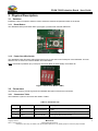
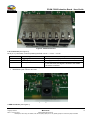
1. RJ45 Connector (see
Figure 5)
A single dedicated RJ45 connector that contains 8 RJ45 ports + light pipe.
Pin No. (Each RJ45) Signal Name Description
4, 5 Alt B – Vport_Pos PoE's Positive.
7, 8 Alt B – Vport_Neg PoE's Negative.
1, 2 N.C
3, 6 N.C
Manufacturer: Molex
Manufacture part number: 44170-0001

PD-IM-7508 Evaluation Board - User Guide
Copyright © 2013
Microsemi
10
Rev 0.1 / 04 Aug 2013 Analog Mixed Signal Group
1 Enterprise, Aliso Viejo, CA 92656, USA; Phone (USA): (800) 713-4113, (ROW): (949) 221-7100 Fax: (949) 756-0308
Figure 5: RJ45 Connectors
2. V
in
Connector (see Figure 6)
DC in (V
main
) connection, used for powering the EVB. 44 57.
Pin No. Signal Name Description
1 V
main
(V
in
+) Main positive voltage (referenced to AGND)
2 AGND (V
in
-) Analog ground
3 RJ45_AGND Analog ground coming from the PD IC. When DC-Jack
is not connected, this signal is shorted to the AGND
net via the connector
Manufacturer: Shogyo International Corp.
Manufacture part number: MJ-179P
Figure 6: V
in
Connector
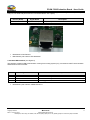
3. PSE Connector (see Figure 7)

PD-IM-7508 Evaluation Board - User Guide
Copyright © 2013
Microsemi
11
Rev 0.1 / 04 Aug 2013 Analog Mixed Signal Group
1 Enterprise, Aliso Viejo, CA 92656, USA; Phone (USA): (800) 713-4113, (ROW): (949) 221-7100 Fax: (949) 756-0308
Another way to power up the EVB is by using a 4 pairs PSE port (EVB supports the usage of either 2pair or 4pair
PSE port, for enhanced performance it is recommended to use 4 pairs).
Pin No. (RJ45) Signal Name Description
4, 5, 7, 8 ALT B – POE input Not polarity sensitive
1, 2, 3, 6 ALT A – POE input Not polarity sensitive
Figure 7: PSE Connector
Manufacturer: Bel Stewart
Manufacture part number: SS71800-007F
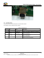
4. Isolated USB Interface (see Figure 8)
This interface supplies USB communication coming from hosting system (U3), converted to UART communication
and directed to PoE controller.
Pin No. Signal Name Description
1
V
bus
Voltage supply from USB bus
2
D- Dedicated USB signal
3
D+ Dedicated USB signal
4
GND_F Floating ground
Manufacturer: Samtec
Manufacture part number: USB-B-S-S-B-TH

PD-IM-7508 Evaluation Board - User Guide
Copyright © 2013
Microsemi
12
Rev 0.1 / 04 Aug 2013 Analog Mixed Signal Group
1 Enterprise, Aliso Viejo, CA 92656, USA; Phone (USA): (800) 713-4113, (ROW): (949) 221-7100 Fax: (949) 756-0308
Figure 8: Isolated USB Interface
3.3 Led Indications
The following sections provide description of the board LED indicators.
The Evaluation system's LEDs are listed in Table 2.
Table 2: Connector List
Number
LED Name Description
1 D1
V
main
Indication that V
main
(POE domain) is present
2 D2 3.3V_CPU Indication that 3.3V of the Host domain is present
3 D3 System_OK System_OK indication LED (driven by PD39100)
4 D4-D11 PortX_LED
Indication LED per port: ON, OFF, PM, OVL/UDL
(driven by PD39100)
5 D31, D34 PD_PGOODx_LED
Indication that the EVB is powered up from either
2pair or 4pair PSE port
(driven by PD70200)
6 D53, D36 ATx_LED
Indication that the PSE is either AT or AF PSE
(ON is AT, driven by PD70200)

PD-IM-7508 Evaluation Board - User Guide
Copyright © 2013
Microsemi
13
Rev 0.1 / 04 Aug 2013 Analog Mixed Signal Group
1 Enterprise, Aliso Viejo, CA 92656, USA; Phone (USA): (800) 713-4113, (ROW): (949) 221-7100 Fax: (949) 756-0308
4 Electrical Characteristics
Evaluation system’s electrical characteristics are described below:
Parameter Symbol Min. Max. Units
Main DC supply V
main
44 57 V
Port Isolation to chassis
-
1.5
kVrms

PD-IM-7508 Evaluation Board - User Guide
Copyright © 2013
Microsemi
14
Rev 0.1 / 04 Aug 2013 Analog Mixed Signal Group
1 Enterprise, Aliso Viejo, CA 92656, USA; Phone (USA): (800) 713-4113, (ROW): (949) 221-7100 Fax: (949) 756-0308
5 Installation
This chapter describes the steps required for installing and operating PD-IM-7508 Evaluation Board. Some
necessary precautions:
Power up the EVB via external PSU or a PSE port, before connecting the USB cable to the
EVB.
In some PCs or laptop, the user will be required to install the UART/USB driver (CP210x
USB to UART Bridge VCP Drivers), which can be taken free from Silabs website,
http://www.silabs.com

PD-IM-7508 Evaluation Board - User Guide
Copyright © 2013
Microsemi
15
Rev 0.1 / 04 Aug 2013 Analog Mixed Signal Group
1 Enterprise, Aliso Viejo, CA 92656, USA; Phone (USA): (800) 713-4113, (ROW): (949) 221-7100 Fax: (949) 756-0308
The information contained in the document is PROPRIETARY AND CONFIDENTIAL information of Microsemi and
cannot be copied, published, uploaded, posted, transmitted, distributed or disclosed or used without the express
duly signed written consent of Microsemi If the recipient of this document has entered into a disclosure agreement
with Microsemi, then the terms of such Agreement will also apply. This document and the information contained
herein may not be modified, by any person other than authorized personnel of Microsemi. No license under any
patent, copyright, trade secret or other intellectual property right is granted to or conferred upon you by disclosure
or delivery of the information, either expressly, by implication, inducement, estoppels or otherwise. Any license
under such intellectual property rights must be approved by Microsemi in writing signed by an officer of Microsemi.
Microsemi reserves the right to change the configuration, functionality and performance of its products at anytime
without any notice. This product has been subject to limited testing and should not be used in conjunction with life-
support or other mission-critical equipment or applications. Microsemi assumes no liability whatsoever, and
Microsemi disclaims any express or implied warranty, relating to sale and/or use of Microsemi products including
liability or warranties relating to fitness for a particular purpose, merchantability, or infringement of any patent,
copyright or other intellectual property right. The product is subject to other terms and conditions which can be
located on the web at http://www.microsemi.com/legal/tnc.asp
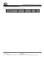
Revision History
Revision Level /
Date
Para. Affected Description
0.1 / 04 Aug 2013 Initial revision
©
2013 Microsemi Corp.
All rights reserved.
Visit our web site at: www.microsemi.com Catalog Number: PD-IM-7508_UG_EVB
All rights reserved.
For support contact: sales_AMSG@microsemi.com
-
 1
1
-
 2
2
-
 3
3
-
 4
4
-
 5
5
-
 6
6
-
 7
7
-
 8
8
-
 9
9
-
 10
10
-
 11
11
-
 12
12
-
 13
13
-
 14
14
-
 15
15


Microsemi PD-IM-7508 User manual
- Type
- User manual
Ask a question and I''ll find the answer in the document
Finding information in a document is now easier with AI
Related papers
-
Microsemi 9501GO-ET User's Installation Manual
-
-
Microsemi PD-IM-7504B User manual
-
-
-
-
-
-
-
Other documents
-
MICROCHIP PD-IM-7401 Operating instructions
-
Silicon Labs CP210x-EK Quick start guide
-
Microchip Technology Microsemi PD70201EVB-25F-D-5 User manual
-
-
-
-
Adaptec 6805TQ with maxCache™ 2.0 User guide
-
-
Adaptec HBA 1000-16i User guide
-