
11
11
1
PV530-ITX
User Manual
Version 1.0
Published June 2010
Copyright©2010 ASRock INC. All rights reserved.

22
22
2
Copyright Notice:Copyright Notice:
Copyright Notice:Copyright Notice:
Copyright Notice:
No part of this manual may be reproduced, transcribed, transmitted, or translated in
any language, in any form or by any means, except duplication of documentation by
the purchaser for backup purpose, without written consent of ASRock Inc.
Products and corporate names appearing in this manual may or may not be regis-
tered trademarks or copyrights of their respective companies, and are used only for
identification or explanation and to the owners’ benefit, without intent to infringe.
Disclaimer:Disclaimer:
Disclaimer:Disclaimer:
Disclaimer:
Specifications and information contained in this manual are furnished for informa-
tional use only and subject to change without notice, and should not be constructed
as a commitment by ASRock. ASRock assumes no responsibility for any errors or
omissions that may appear in this manual.
With respect to the contents of this manual, ASRock does not provide warranty of
any kind, either expressed or implied, including but not limited to the implied warran-
ties or conditions of merchantability or fitness for a particular purpose.
In no event shall ASRock, its directors, officers, employees, or agents be liable for
any indirect, special, incidental, or consequential damages (including damages for
loss of profits, loss of business, loss of data, interruption of business and the like),
even if ASRock has been advised of the possibility of such damages arising from any
defect or error in the manual or product.
This device complies with Part 15 of the FCC Rules. Operation is subject to the
following two conditions:
(1) this device may not cause harmful interference, and
(2) this device must accept any interference received, including interference that
may cause undesired operation.
CALIFORNIA, USA ONLY
The Lithium battery adopted on this motherboard contains Perchlorate, a toxic
substance controlled in Perchlorate Best Management Practices (BMP) regulations
passed by the California Legislature. When you discard the Lithium battery in
California, USA, please follow the related regulations in advance.
“Perchlorate Material-special handling may apply, see
www.dtsc.ca.gov/hazardouswaste/perchlorate”
ASRock Website: http://www.asrock.com

33
33
3
ContentsContents
ContentsContents
Contents
1 Introduction1 Introduction
1 Introduction1 Introduction
1 Introduction
......................................................................................................
......................................................................................................
...................................................
5 5
5 5
5
1.1 Package Contents.......................................................... 5
1.2 Specifications ................................................................ 6
1.3 Motherboard Layout ...................................................... 10
1.4 I/O Panel......................................................................... 11
2 Installation2 Installation
2 Installation2 Installation
2 Installation
............................................................................................................
............................................................................................................
......................................................
12 12
12 12
12
2.1 Screw Holes ................................................................. 12
2.2 Pre-installation Precautions........................................... 12
2.3 Installation of Memory Modules (DIMM)......................... 13
2.4 Expansion Slot (PCI Slot) ...................................................... 14
2.5 Jumpers Setup .............................................................. 15
2.6 Onboard Headers and Connectors .............................. 16
2.7 SATAII Hard Disk Setup Guide ....................................... 18
2.8 Serial ATA (SATA) / Serial ATAII (SATAII) Hard Disks
Installation ...................................................................... 19
2.9 Driver Installation Guide ............................................... 20
2.10 Untied Overclocking Technology................................... 20
3 BIOS S3 BIOS S
3 BIOS S3 BIOS S
3 BIOS S
ETUP UTILITYETUP UTILITY
ETUP UTILITYETUP UTILITY
ETUP UTILITY
......................................................................................
......................................................................................
...........................................
21 21
21 21
21
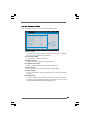
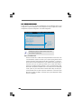
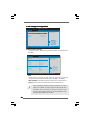
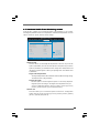
3.1 Introduction .................................................................... 21
3.1.1 BIOS Menu Bar .................................................... 21
3.1.2 Navigation Keys ................................................... 22
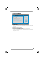
3.2 Main Screen................................................................... 22
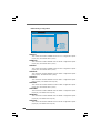
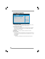
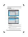
3.3 OC Tweaker Screen...................................................... 23
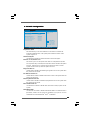
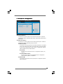
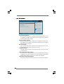
3.4 Advanced Screen ......................................................... 26
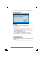
3.4.1 CPU Configuration................................................ 27
3.4.2 Chipset Configuration .......................................... 28
3.4.3 ACPI Configuration ............................................... 29
3.4.4 Storage Configuration ......................................... 30
3.4.5 PCIPnP Configuration ........................................... 32
3.4.6 Super IO Configuration ........................................ 33
3.4.7 USB Configuration ............................................... 34
3.5 Hardware Health Event Monitoring Screen .................. 35
3.6 Boot Screen................................................................... 36
3.6.1 Boot Settings Configuration.................................. 36
3.7 Security Screen ............................................................ 37
3.8 Exit Screen .................................................................... 38

44
44
4
4 Software Support4 Software Support
4 Software Support4 Software Support
4 Software Support
......................................................................................
......................................................................................
...........................................
39 39
39 39
39
4.1 Install Operating System ............................................... 39
4.2 Support CD Information ................................................. 39
4.2.1 Running Support CD ............................................ 39
4.2.2 Drivers Menu ........................................................ 39
4.2.3 Utilities Menu ........................................................ 39
4.2.4 Contact Information .............................................. 39

55
55
5
Chapter 1 IntroductionChapter 1 Introduction
Chapter 1 IntroductionChapter 1 Introduction
Chapter 1 Introduction
Thank you for purchasing ASRock PV530-ITX motherboard, a reliable motherboard
produced under ASRock’s consistently stringent quality control. It
delivers excellent performance with robust design conforming to ASRock’s
commitment to quality and endurance.
In this manual, chapter 1 and 2 contain introduction of the motherboard and
step-by-step guide to the hardware installation. Chapter 3 and 4 contain the
configuration guide to BIOS setup and information of the Support CD.
Because the motherboard specifications and the BIOS software might be
updated, the content of this manual will be subject to change without
notice. In case any modifications of this manual occur, the updated
version will be available on ASRock website without further notice. You
may find the latest VGA cards and CPU support lists on ASRock website
as well. ASRock website
http://www.asrock.com
If you require technical support related to this motherboard, please visit
our website for specific information about the model you are using.
www.asrock.com/support/index.asp
1.1 P1.1 P
1.1 P1.1 P
1.1 P
ackack
ackack
ack
age Contentsage Contents
age Contentsage Contents
age Contents
ASRock PV530-ITX Motherboard
(Mini-ITX Form Factor: 6.7-in x 6.7-in, 17.0 cm x 17.0 cm)
ASRock PV530-ITX Quick Installation Guide
ASRock PV530-ITX Support CD
Two Serial ATA (SATA) Data Cables (Optional)
One I/O Panel Shield

66
66
6
1.21.2
1.21.2
1.2
SpecificationsSpecifications
SpecificationsSpecifications
Specifications
Platform - Mini-ITX Form Factor: 6.7-in x 6.7-in, 17.0 cm x 17.0 cm
- Solid Capacitor for CPU power
CPU - VIA
®
PV530 Processor (1.8 GHz)
- Supports FSB800 MHz
- Supports Untied Overclocking Technology (see CAUTION 1)
Chipset - VIA
®
VX900
Memory - 2 x DDR3 DIMM slots
- Supports DDR3 1066/800 non-ECC, un-buffered memory
(see CAUTION 2)
- Max. capacity of system memory: 4GB (see CAUTION 3)
Expansion Slot - 1 x PCI slot
Graphics - VIA
®
Chrome9 HD DX9 Graphics
- Pixel Shader 2.0, DirectX 9.0
- Max. shared memory 512MB (see CAUTION 4)
- Supports D-Sub with max. resolution up to 2048x1536
@ 75Hz
Audio - 5.1 CH HD Audio (VIA
®
VT1705 Audio Codec)
LAN - Realtek PCIE x1 LAN 8105E
- Speed: 10/100 Ethernet
- Supports Wake-On-LAN
Rear Panel I/O I/O Panel
- 1 x PS/2 Mouse Port
- 1 x PS/2 Keyboard Port
- 1 x Parallel Port (ECP/EPP Support)
- 1 x Serial Port: COM1
- 1 x VGA Port
- 4 x Ready-to-Use USB 2.0 Ports
- 1 x RJ-45 LAN Port with LED (ACT/LINK LED and SPEED LED)
- HD Audio Jack: Line in / Front Speaker / Microphone
Connector - 2 x SATAII 3.0 Gb/s connectors (see CAUTION 5)
- CPU/Chassis FAN connector
- 24 pin ATX power connector
- Front panel audio connector
- 2 x USB 2.0 headers (support 4 USB 2.0 ports)

77
77
7
BIOS Feature - 4Mb AMI BIOS
- AMI Legal BIOS
- Supports “Plug and Play”
- ACPI 1.1 Compliance Wake Up Events
- Supports jumperfree
- AMBIOS 2.3.1 Support
Support CD - Drivers, Utilities, AntiVirus Software (Trial Version), ASRock
Software Suite (CyberLink DVD Suite - OEM and Trial;
Creative Sound Blaster X-Fi MB - Trial)
Unique Feature - ASRock OC Tuner (see CAUTION 6)
- Instant Boot
- ASRock Instant Flash (see CAUTION 7)
- ASRock OC DNA (see CAUTION 8)
- Hybrid Booster:
- CPU Frequency Stepless Control (see CAUTION 9)
- ASRock U-COP (see CAUTION 10)
- Boot Failure Guard (B.F.G.)
Hardware - CPU Temperature Sensing
Monitor - Chassis Temperature Sensing
- CPU Fan Tachometer
- Chassis Fan Tachometer
- CPU Quiet Fan
- CPU/Chassis Fan Multi-Speed Control
- Voltage Monitoring: +12V, +5V, +3.3V, Vcore
OS - Microsoft
®
Windows
®
7 / Vista
TM
/ XP compliant
Certifications - FCC, CE, WHQL
- ErP/EuP Ready (ErP/EuP ready power supply is required)
(see CAUTION 11)
* For detailed product information, please visit our website: http://www.asrock.com
WARNING
Please realize that there is a certain risk involved with overclocking, including adjusting
the setting in the BIOS, applying Untied Overclocking Technology, or using the third-
party overclocking tools. Overclocking may affect your system stability, or even
cause damage to the components and devices of your system. It should be done at
your own risk and expense. We are not responsible for possible damage caused by
overclocking.

88
88
8
CAUTION!
1. This motherboard supports Untied Overclocking Technology. Please read “Un-
tied Overclocking Technology” on page 20 for details.
2. DDR3 1066 memory module can only be installed in one of the DDR3 DIMM
slots. If you install two DDR3 1066 memory modules on this motherboard,
they will run at DDR3 800.
3. Due to the chipset limitation, the actual memory size may be less than
4GB for the reservation for system usage under Windows
®
OS.
4. The maximum shared memory size is defined by the chipset vendor and
is subject to change. Please check VIA
®
website for the latest information.
5. Before installing SATAII hard disk to SATAII connector, please read the “SATAII
Hard Disk Setup Guide” on page 18 to adjust your SATAII hard disk drive to
SATAII mode. You can also connect SATA hard disk to SATAII connector
directly.
6. It is a user-friendly ASRock overclocking tool which allows you to surveil
your system by hardware monitor function and overclock your hardware
devices to get the best system performance under Windows
®
environment.
Please visit our website for the operation procedures of ASRock OC
Tuner. ASRock website: http://www.asrock.com
7. ASRock Instant Flash is a BIOS flash utility embedded in Flash ROM.
This convenient BIOS update tool allows you to update system BIOS
without entering operating systems first like MS-DOS or Windows
®
. With
this utility, you can press <F6> key during the POST or press <F2> key to
BIOS setup menu to access ASRock Instant Flash. Just launch this tool
and save the new BIOS file to your USB flash drive, floppy disk or hard
drive, then you can update your BIOS only in a few clicks without prepar-
ing an additional floppy diskette or other complicated flash utility. Please
be noted that the USB flash drive or hard drive must use FAT32/16/12 file
system.
8. The software name itself – OC DNA literally tells you what it is capable of.
OC DNA, an exclusive utility developed by ASRock, provides a conve-
nient way for the user to record the OC settings and share with others. It
helps you to save your overclocking record under the operating system
and simplifies the complicated recording process of overclocking settings.
With OC DNA, you can save your OC settings as a profile and share with
your friends! Your friends then can load the OC profile to their own system
to get the same OC settings as yours! Please be noticed that the OC
profile can only be shared and worked on the same motherboard.
9. Although this motherboard offers stepless control, it is not recommended
to perform over-clocking. Frequencies other than the recommended CPU
bus frequencies may cause the instability of the system or damage the
CPU.

99
99
9
10. While CPU overheat is detected, the system will automatically shutdown.
Before you resume the system, please check if the CPU fan on the
motherboard functions properly and unplug the power cord, then plug it
back again. To improve heat dissipation, remember to spray thermal
grease between the CPU and the heatsink when you install the PC system.
11. EuP, stands for Energy Using Product, was a provision regulated by
European Union to define the power consumption for the completed system.
According to EuP, the total AC power of the completed system shall be
under 1.00W in off mode condition. To meet EuP standard, an EuP ready
motherboard and an EuP ready power supply are required. According to
Intel’s suggestion, the EuP ready power supply must meet the standard of
5v standby power efficiency is higher than 50% under 100 mA current
consumption. For EuP ready power supply selection, we recommend you
checking with the power supply manufacturer for more details.

1010
1010
10
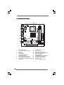
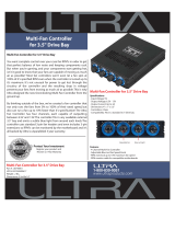
1.3 Motherboard Layout1.3 Motherboard Layout
1.3 Motherboard Layout1.3 Motherboard Layout
1.3 Motherboard Layout
1 PS2_USB_PWR1 Jumper 11 USB_PWR3 Jumper
2 Chassis Fan Connector (CHA_FAN1) 12 PCI Slot (PCI1)
3 CPU Fan 13 USB 2.0 Header (USB6_7, Blue)
4 CPU Heatsink 14 Primary SATAII Connector (SATAII_1; Blue)
5 VIA VX900 Chipset 15 Front Panel Audio Header
6 2 x 240-pin DDR3 DIMM Slots (HD_AUDIO1, White)
(DDR3_1, DDR3_2; Blue) 16 Secondary SATAII Connector (SATAII_2; Blue)
7 ATX Power Connector (ATXPWR1) 17 USB 2.0 Header (USB4_5, Blue)
8 System Panel Header (PANEL1, White) 18 Clear CMOS Jumper (CLRCMOS1)
9 Chassis Speaker Header (SPEAKER 1, White) 19 USB_PWR2 Jumper
10 BIOS SPI Chip 20 CPU Fan Connector (CPU_FAN1)
PS2
Mouse
PS2
Keyboard
PARALLEL PORT
VGA1
COM1
USB 2.0
T: USB0
B: USB1
Top:
RJ-45
USB 2.0
T: USB2
B: USB3
Top :
Line In
Center:
Line Out
Bottom:
Mic In
17.0cm (6.7 in)
17.0cm (6.7 in)
FSB800
DDR3_1 (64 bit, 240-pin module)
FSB800
DDR3_2 (64 bit, 240-pin module)
PV530-ITX
ErP/EuP Ready
4Mb
BIOS
CMOS
Battery
Super
IO
PCI1
SATAII_1
SATAII_2
1
USB6_7
1
USB4_5
CLRCMOS1
AUDIO
CODEC
LAN
PHY
HD_AUDIO1
1
SPEAKER1
1
PANE L 1
HDLED RESET
PLED PWRBTN
1
CHA_FAN1
CPU_FAN1
1
PS2_USB_PWR1
DDR3
Designed in Taipei
1
USB_PWR2
RoHS
1
USB_PWR3
1
2
4
5
7
6
3
8
910
12
13
14
11
15
16
17
18
19
20

1111
1111
11
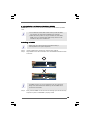
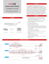
1.4 I/O Panel1.4 I/O Panel
1.4 I/O Panel1.4 I/O Panel
1.4 I/O Panel
1 PS/2 Mouse Port (Green) 7 USB 2.0 Ports (USB01)
2 Parallel Port 8 USB 2.0 Ports (USB23)
3 RJ-45 Port 9 VGA Port
4 Line In (Light Blue) 10 COM Port
5 Line Out (Lime) 11 PS/2 Keyboard Port (Purple)
6 Microphone (Pink)
1
3
7
8
5
4
6
9
10
11
2
LAN Port
ACT/LINK
LED
SPEED
LED
* There are two LED next to the LAN port. Please refer to the table below for the LAN port LED
indications.
LAN Port LED Indications
Activity/Link LED SPEED LED
Status Description Status Description
Off No Activity Off 10Mbps connection
Blinking Data Activity Green 100Mbps connection
To enable Multi-Streaming function, you need to connect a front panel audio cable to the front
panel audio header. After restarting your computer, you will find “VIA HD Audio Deck” tool on
your system. Please follow below instructions according to the OS you install.
For Windows
®
XP OS:
Please click “VIA HD Audio Deck” icon , and click “Speaker”. Then you are allowed to
select “2 Channel” or “4 Channel”. Click “Power” to save your change.
For Windows
®
7 / Vista
TM
OS:
Please click “VIA HD Audio Deck” icon , and click “Advanced Options” on the left side
on the bottom. In “Advanced Options” screen, select “Independent Headphone”, and click
“OK” to save your change.

1212
1212
12
Chapter 2 InstallationChapter 2 Installation
Chapter 2 InstallationChapter 2 Installation
Chapter 2 Installation
PV530-ITX is a Mini-ITX form factor (6.7" x 6.7", 17.0 x 17.0 cm) motherboard.
Before you install the motherboard, study the configuration of your chassis to
ensure that the motherboard fits into it.
Make sure to unplug the power cord before installing or removing the
motherboard. Failure to do so may cause physical injuries to you and
damages to motherboard components.
2.1 Screw Holes2.1 Screw Holes
2.1 Screw Holes2.1 Screw Holes
2.1 Screw Holes
Place screws into the holes indicated by circles to secure the motherboard to the
chassis.
Do not over-tighten the screws! Doing so may damage the motherboard.
2.2 Pre-installation Precautions2.2 Pre-installation Precautions
2.2 Pre-installation Precautions2.2 Pre-installation Precautions
2.2 Pre-installation Precautions
Take note of the following precautions before you install motherboard components
or change any motherboard settings.
1. Unplug the power cord from the wall socket before touching any component.
2. To avoid damaging the motherboard components due to static electricity, NEVER
place your motherboard directly on the carpet or the like. Also remember to use
a grounded wrist strap or touch a safety grounded object before you handle
components.
3. Hold components by the edges and do not touch the ICs.
4. Whenever you uninstall any component, place it on a grounded antistatic pad or
in the bag that comes with the component.
Before you install or remove any component, ensure that the power is
switched off or the power cord is detached from the power supply.
Failure to do so may cause severe damage to the motherboard, peripherals,
and/or components.

1313
1313
13
notch
break
notch
break
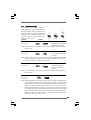
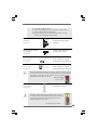
2.3 Installation of Memory Modules (DIMM)2.3 Installation of Memory Modules (DIMM)
2.3 Installation of Memory Modules (DIMM)2.3 Installation of Memory Modules (DIMM)
2.3 Installation of Memory Modules (DIMM)
PV530-ITX motherboard provides two 240-pin DDR3 (Double Data Rate 3) DIMM
slots.
1. It is not allowed to install a DDR or DDR2 memory module into DDR3
slot; otherwise, this motherboard and DIMM may be damaged.
2. DDR3 1066 memory module can only be installed in one of the DDR3
DIMM slots. If you install two DDR3 1066 memory modules on this
motherboard, they will run at DDR3 800.
Installing a DIMMInstalling a DIMM
Installing a DIMMInstalling a DIMM
Installing a DIMM
Please make sure to disconnect power supply before adding or
removing DIMMs or the system components.
Step 1. Unlock a DIMM slot by pressing the retaining clips outward.
Step 2. Align a DIMM on the slot such that the notch on the DIMM matches the break
on the slot.
The DIMM only fits in one correct orientation. It will cause permanent
damage to the motherboard and the DIMM if you force the DIMM into the
slot at incorrect orientation.
Step 3. Firmly insert the DIMM into the slot until the retaining clips at both ends fully
snap back in place and the DIMM is properly seated.

1414
1414
14
2.4 Expansion Slots (PCI and PCI Express Slots)2.4 Expansion Slots (PCI and PCI Express Slots)
2.4 Expansion Slots (PCI and PCI Express Slots)2.4 Expansion Slots (PCI and PCI Express Slots)
2.4 Expansion Slots (PCI and PCI Express Slots)
There is 1 PCI slot on this motherboard.
PCI Slot: PCI slot is used to install expansion card that has the 32-bit PCI
interface.
Installing an expansion cardInstalling an expansion card
Installing an expansion cardInstalling an expansion card
Installing an expansion card
Step 1. Before installing the expansion card, please make sure that the power
supply is switched off or the power cord is unplugged. Please read the
documentation of the expansion card and make necessary hardware
settings for the card before you start the installation.
Step 2. Remove the system unit cover (if your motherboard is already installed in
a chassis).
Step 3. Remove the bracket facing the slot that you intend to use. Keep the
screws for later use.
Step 4. Align the card connector with the slot and press firmly until the card is
completely seated on the slot.
Step 5. Fasten the card to the chassis with screws.
Step 6. Replace the system cover.

1515
1515
15
+5V
1_2
+5VSB
2_3
2.52.5
2.52.5
2.5
Jumpers SetupJumpers Setup
Jumpers SetupJumpers Setup
Jumpers Setup
The illustration shows how jumpers are
setup. When the jumper cap is placed on
pins, the jumper is “Short”. If no jumper cap
is placed on pins, the jumper is “Open”. The
illustration shows a 3-pin jumper whose pin1
and pin2 are “Short” when jumper cap is
placed on these 2 pins.
Jumper Setting
PS2_USB_PWR1 Short pin2, pin3 to enable
(see p.10, No. 1) +5VSB (standby) for PS/2 or
USB23 wake up events.
Note: To select +5VSB, it requires 2 Amp and higher standby current provided by
power supply.
USB_PWR2 Short pin2, pin3 to enable
(see p.10, No. 19) +5V_DUAL for USB01 wake
up events.
Note: To select +5V_DUAL, it requires 2 Amp and higher standby current provided
by power supply. When you select +5V_DUAL, USB devices can wake up
the system under S3 (Suspend to RAM) state.
USB_PWR3 Short pin2, pin3 to enable
(see p.10, No. 11) +5VSB (standby) for
USB4_5/6_7 wake up
events.
Note: To select +5VSB, it requires 2 Amp and higher standby current provided by
power supply.
Clear CMOS Jumper
(CLRCMOS1)
(see p.10, No. 18)
Note: CLRCMOS1 allows you to clear the data in CMOS. The data in CMOS includes
system setup information such as system password, date, time, and system
setup parameters. To clear and reset the system parameters to default setup,
please turn off the computer and unplug the power cord from the power
supply. After waiting for 15 seconds, use a jumper cap to short pin2 and pin3
on CLRCMOS1 for 5 seconds. However, please do not clear the CMOS right
after you update the BIOS. If you need to clear the CMOS when you just finish
updating the BIOS, you must boot up the system first, and then shut it down
before you do the clear-CMOS action.
Clear CMOS
2_3
1_2
Default
+5V
1_2
+5VSB
2_3
+5V
1_2
+5V_DUAL

1616
1616
16
J_SENSE
OUT2_L
1
MIC_RET
PRESENCE#
GND
OUT2_R
MIC2_R
MIC2_L
OUT_RET
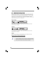
Front Panel Audio Header This is an interface for front
(9-pin HD_AUDIO1) panel audio cable that allows
(see p.10 No. 15) convenient connection and
control of audio devices.
USB 2.0 Headers Besides four default USB 2.0
(9-pin USB6_7) ports on the I/O panel, there are
(see p.10 No. 13) two USB 2.0 headers on this
motherboard. Each USB 2.0
header cansupport two USB
2.0 ports.
(9-pin USB4_5)
(see p.10 No. 17)
USB_P WR
USB_P WR
P +7
P-7
P +6
P-6
GND
GND
DUMMY
1
USB _PWR
USB _PWR
P+5
P-5
P+4
P-4
GND
GND
DUMMY
1
2.6 Onboard Headers and Connectors2.6 Onboard Headers and Connectors
2.6 Onboard Headers and Connectors2.6 Onboard Headers and Connectors
2.6 Onboard Headers and Connectors
Onboard headers and connectors are NOT jumpers. Do NOT place
jumper caps over these headers and connectors. Placing jumper caps
over the headers and connectors will cause permanent damage of the
motherboard!
Serial ATAII Connectors These Serial ATAII (SATAII)
(SATAII_1: see p.10, No. 14) connectors support SATAII
(SATAII_2: see p.10, No. 16) or SATA hard disk for internal
storage devices. The current
SATAII interface allows up to
3.0 Gb/s data transfer rate.
Serial ATA (SATA) Either end of the SATA data cable
Data Cable can be connected to the SATA /
(Optional) SATAII hard disk or the SATAII
connector on the motherboard.
SATAII_2
SATAII_1
1. High Definition Audio supports Jack Sensing, but the panel wire on
the chassis must support HDA to function correctly. Please follow the
instruction in our manual and chassis manual to install your system.
2. If you use AC’97 audio panel, please install it to the front panel audio
header as below:

1717
1717
17
+5V
DUMMY
DUMMY
SPEAKER
1
GND
PWRB TN#
PLED-
PLED+
DUMMY
RESET#
GND
HDLED+
HDLED-
1
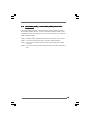
System Panel Header This header accommodates
(9-pin PANEL1) several system front panel
(see p.10 No. 8) functions.
Chassis Speaker Header Please connect the chassis
(4-pin SPEAKER 1) speaker to this header.
(see p.10 No. 9)
Chassis Fan Connector Please connect a CPU fan cable
(4-pin CHA_FAN1) to this connector and match
(see p.10 No. 2) the black wire to the ground pin.
CPU Fan Connector Please connect a CPU fan cable
(4-pin CPU_FAN1) to this connector and match
(see p.10 No. 20) the black wire to the ground pin.
ATX Power Connector Please connect an ATX power
(24-pin ATXPWR1) supply to this connector.
(see p.10, No. 7)
A. Connect Mic_IN (MIC) to MIC2_L.
B. Connect Audio_R (RIN) to OUT2_R and Audio_L (LIN) to OUT2_L.
C. Connect Ground (GND) to Ground (GND).
D. MIC_RET and OUT_RET are for HD audio panel only. You don’t
need to connect them for AC’97 audio panel.
Though this motherboard provides 4-Pin CPU fan (Quiet Fan) support, the 3-Pin
CPU fan still can work successfully even without the fan speed control function.
If you plan to connect the 3-Pin CPU fan to the CPU fan connector on this
motherboard, please connect it to Pin 1-3.
3-Pin Fan Installation
Pin 1-3 Connected
20-Pin ATX Power Supply Installation
Though this motherboard provides 24-pin ATX power connector,
it can still work if you adopt a traditional 20-pin ATX power supply.
To use the 20-pin ATX power supply, please plug your power
supply along with Pin 1 and Pin 13.
12
1
24
13
12
1
24
13
GND
+12V
CPU_FAN_SPEED
FAN_SPEED_CONTROL
1
2
3
4
GND
+12V
CHA_FAN_SPEED
FAN_SPEED_CONTROL

1818
1818
18
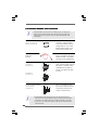
2.72.7
2.72.7
2.7
SASA
SASA
SA
TT
TT
T
AII Hard Disk Setup GuideAII Hard Disk Setup Guide
AII Hard Disk Setup GuideAII Hard Disk Setup Guide
AII Hard Disk Setup Guide
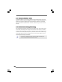
Before installing SATAII hard disk to your computer, please carefully read below
SATAII hard disk setup guide. Some default setting of SATAII hard disks may not
be at SATAII mode, which operate with the best performance. In order to enable
SATAII function, please follow the below instruction with different vendors to
correctly adjust your SATAII hard disk to SATAII mode in advance; otherwise, your
SATAII hard disk may fail to run at SATAII mode.
Western Digital
If pin 5 and pin 6 are shorted, SATA 1.5Gb/s will be enabled.
On the other hand, if you want to enable SATAII 3.0Gb/s, please remove the
jumpers from pin 5 and pin 6.
SAMSUNG
If pin 3 and pin 4 are shorted, SATA 1.5Gb/s will be enabled.
On the other hand, if you want to enable SATAII 3.0Gb/s, please remove the
jumpers from pin 3 and pin 4.
HITACHI
Please use the Feature Tool, a DOS-bootable tool, for changing various ATA
features. Please visit HITACHI’s website for details:
http://www.hitachigst.com/hdd/support/download.htm
1357
2468
1357
2468
The above examples are just for your reference. For different SATAII hard
disk products of different vendors, the jumper pin setting methods may not
be the same. Please visit the vendors’ website for the updates.

1919
1919
19
2.82.8
2.82.8
2.8
Serial ASerial A
Serial ASerial A
Serial A
TT
TT
T
A (SAA (SA
A (SAA (SA
A (SA
TT
TT
T
A) / Serial AA) / Serial A
A) / Serial AA) / Serial A
A) / Serial A
TT
TT
T
AII (SAAII (SA
AII (SAAII (SA
AII (SA
TT
TT
T
AII) Hard DisksAII) Hard Disks
AII) Hard DisksAII) Hard Disks
AII) Hard Disks
InstallationInstallation
InstallationInstallation
Installation
This motherboard adopts VIA
®
VX900 chipset that supports Serial ATA (SATA) /
Serial ATAII (SATAII) hard disks. You may install SATA / SATAII hard disks on this
motherboard for internal storage devices. This section will guide you to install the
SATA / SATAII hard disks.
STEP 1: Install the SATA / SATAII hard disks into the drive bays of your chassis.
STEP 2: Connect the SATA power cable to the SATA / SATAII hard disk.
STEP 3: Connect one end of the SATA data cable to the motherboard’s SATAII
connector.
STEP 4: Connect the other end of the SATA data cable to the SATA / SATAII hard
disk.

2020
2020
20
2.102.10
2.102.10
2.10
Untied Overclocking TUntied Overclocking T
Untied Overclocking TUntied Overclocking T
Untied Overclocking T
echnologyechnology
echnologyechnology
echnology
This motherboard supports Untied Overclocking Technology, which means during
overclocking, FSB enjoys better margin due to fixed PCI bus. Before you enable
Untied Overclocking function, please enter “Overclock Mode” option of BIOS setup
to set the selection from [Auto] to [Manual]. Therefore, CPU FSB is untied during
overclocking, but PCI buse is in the fixed mode so that FSB can operate under a
more stable overclocking environment.
Please refer to the warning on page 7 for the possible overclocking risk
before you apply Untied Overclocking Technology.
2.92.9
2.92.9
2.9
Driver Installation GuideDriver Installation Guide
Driver Installation GuideDriver Installation Guide
Driver Installation Guide
To install the drivers to your system, please insert the support CD to your optical
drive first. Then, the drivers compatible to your system can be auto-detected and
listed on the support CD driver page. Please follow the order from up to bottom
side to install those required drivers. Therefore, the drivers you install can work
properly.
Page is loading ...
Page is loading ...
Page is loading ...
Page is loading ...
Page is loading ...
Page is loading ...
Page is loading ...
Page is loading ...
Page is loading ...
Page is loading ...
Page is loading ...
Page is loading ...
Page is loading ...
Page is loading ...
Page is loading ...
Page is loading ...
Page is loading ...
Page is loading ...
Page is loading ...
-
 1
1
-
 2
2
-
 3
3
-
 4
4
-
 5
5
-
 6
6
-
 7
7
-
 8
8
-
 9
9
-
 10
10
-
 11
11
-
 12
12
-
 13
13
-
 14
14
-
 15
15
-
 16
16
-
 17
17
-
 18
18
-
 19
19
-
 20
20
-
 21
21
-
 22
22
-
 23
23
-
 24
24
-
 25
25
-
 26
26
-
 27
27
-
 28
28
-
 29
29
-
 30
30
-
 31
31
-
 32
32
-
 33
33
-
 34
34
-
 35
35
-
 36
36
-
 37
37
-
 38
38
-
 39
39


Ask a question and I''ll find the answer in the document
Finding information in a document is now easier with AI
Related papers
-
ASROCK PV530A-ITX Owner's manual
-
-
ASROCK PV530 Owner's manual
-
-
ASROCK AD525PV - V1.0 User manual
-
ASROCK PV530A User manual
-
ASROCK AD425PV3 User manual
-
-
ASROCK G41M-VS3 R2.0 User manual
-
Other documents
-
 Curtis Computer VoomPC-2 User manual
-
Gigabyte GA-6UASL3 User manual
-
Samsung HD203WI User manual
-
Gateway NV53A User manual
-
 Ultra Products ULT40061 User manual
-
 Intercoax 2808RM Owner's manual
-
VIA Technologies COMe-8X91 User manual
-
 Intercoax EUP-2816RM Owner's manual
-
American Megatrends MAN-3200-SG User manual


