Rointe VENICE Owner's manual
- Category
- Water heaters & boilers
- Type
- Owner's manual

Compact digital electric D.W.H. heater
INSTRUCTION & INSTALLATION GUIDE
Venice

2

3
Compact digital electric D.W.H. heater
Venice
Contents
1.
General...........................................................................................................................................................................................4
2.
Important rules............................................................................................................................................................................4
3.
Description and information....................................................................................................................................................4
4.
Installation....................................................................................................................................................................................5
5.
Operation....................................................................................................................................................................................10
6.
Protection against magnesium anode oxidation.................................................................................................................11
7.
Periodic maintenance ...............................................................................................................................................................11
8.
Rointe Product Guarantee.......................................................................................................................................................12
9.
European Directive....................................................................................................................................................................13
10.
Dimensions & Technical Characteristics...............................................................................................................................14
11.
Certicate of Guarantee...........................................................................................................................................................15
IMPORTANT
Please read this Instruction Manual carefully to ensure correct operation. It is important that the
installer reads and understands these instructions and unpacks and familiarises themselves with
the equipment before commencing the installation. Please leave this manual with the product after
installation. Failure to observe these installation instructions could render the guarantee null and
void.
PLEASE NOTE
Thank you for choosing the VENICE D.H.W. compact heater. Manufactured with the highest quality
components, the VENICE Compact was designed for you.
The VENICE Compact domestic hot water heater has passed the most stringent quality controls to
meet the highest safety requirements. Before starting to use the VENICE Compact hot water heater,
we recommend that you read this manual carefully. Failure to observe these installation instructions
could cancel the guarantee and render it invalid.

4
1. GENERAL
The VENICE Compact supplies domestic hot water to households equipped with a piping system that
operates at a pressure of less than 6 bar (0.6 Mpa).
It is designed to work in closed spaces, where the temperature does not drop below 4ºC.
The device is not designed to work continuously.
2. IMPORTANT RULES
• This model should only be mounted in enclosures with normal re safety.
• The water heater must only be connected when the tank is full of water.
• When connecting the water heater to the electric current, special care must be taken when connecting
the safety cable.
• The water heater must be completely emptied if freezing temperatures are expected.
• The safety valve should be left open and it is normal for water to drip through the drain opening during
use. In case of water leaks, appropriate measures should be taken to avoid damage.
• During the heating process, the resistance can emit a slight noise (boiling water). This is normal and
does not mean there is a problem. However, if the noise increases over time, lime scale may have
accumulated. It is necessary to clean the appliance (removing the lime scale) to eliminate the noise. This
type of cleaning is not covered by the guarantee.
• The valve and its components must be protected against freezing.
• The safety return valve must be inspected and cleaned periodically to ensure correct functioning of the
heater.
• It is strictly forbidden to make modications or changes, both in the structure and in all electrical
components of the water heater. Failure to observe this will cancel your guarantee and render it invalid.
Modications/changes include (but not limited to): the removal of parts or original components of the
manufacturer, the incorporation of additional elements or the replacement of parts that have not been
approved by the manufacturer.
• If the power cable (if included) suers damage, it must be replaced by Rointe’s ocial Technical Service (please
call 0203 321 5929) or by a competent professional with the appropriate training, in order to avoid any risk.
• The product can be used by children aged from 8 years and above and by persons with reduced physical
sensory or mental capabilities or lack of experience and knowledge, if they are supervised or have been
given instruction concerning use of the product in a safe way and understand the hazards involved. The
product is not a toy, children should not play with the product. Cleaning and user maintenance should
not be carried out by children without supervision. Children must be supervised at all times to ensure
that they do not interfere with the product.
3. DESCRIPTION AND INFORMATION
The water heater consists of a body, ange, plastic control panel and anti-return safety valve.
1.
The body of the heater consists of a steel tank (water tank) and plastic housing (external cover), with
thermal insulation placed in the middle. There is also two pipes with G ½ “thread, for the supply of cold

5
water (marked with a blue ring) and hot water discharge (marked with a red ring). The interior of the tank
is made of steel, treated against corrosion by a special glass-ceramic coating.
2.
The ange is equipped with an electrical resistance and magnesium anode. The ange is xed in the
water tank with bolts.
The electric resistance heats the water in the tank and is controlled by the thermostat, which automatically
maintains the programmed temperature.
The plastic control panel incorporates: the ignition switch (depending on the model), adjustable thermostat
(depending on the model) and control lights. For thermal protection, a device is incorporated that disconnects
the water heater from the power supply when the water temperature reaches excessive values. If the device
is activated, you must call the Rointe Technical Service. The control lights (depending on the model) indicate
the current mode of the unity.
The return safety valve prevents complete emptying of the appliance in case of cold water supply interruption.
The valve protects the device from pressure increases above the allowed value during heating, releasing excess
pressure through the drain outlet. The water that drips through the drain during the heating process does not
indicate any problem. This is a normal occurrence.
IMPORTANT: The protection valve cannot guarantee the protection of the water heater when the water supply
is produced at a higher pressure than that determined for the water heater.
4. INSTALLATION
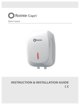
4.1. Installation
We recommend that the water heater is installed in the vicinity where hot water is required, in order to
reduce heat loss. The selected location should exclude the
possibility of splashing water from the shower or other
contacts with water. The appliance should be installed
on a wall by means of mounting brackets. Two screws
are used to x the device (minimum Ø 6 mm) rmly on
the wall. These are included in the mounting kit. The
installation templates either above or below the stack are
universal and allow the space between the bolts to vary
between 96 and 114mm.m.
IMPORTANT: The water heater models suitable to be installed below/above the battery are indicated on the water
heater. The water heater suitable for the installation below the stack are mounted in such a way that the outlet/
inlet of the pipes are pointed downwards (towards the oor). The water heater suitable for the installation on the
stack are mounted in such a way that the outlet/inlet of the pipes are pointed upwards (towards the ceiling).
ATTENTION: In order to avoid injury to the user and/or third parties in case of faults in the hot water supply
system, the appliance must be installed in facilities equipped with waterproof ooring. Do not place objects
that are not waterproof under the device under any circumstances.
min 96 mm
max 114 mm
8 mm

6
4.2. Hydraulic connections
When connecting the water heater to the water supply system, pay attention to the indicative color markings
(rings) of the pipes: blue for cold water and red for hot water.
The assembly and installation of the return safety valve supplied with the water heater is mandatory for safety.
EXCEPTION: If local regulations require the use of another safety valve or device (complying with EN 1487 or
EN 1489 standards) they must be purchased separately. For devices that comply with the EN 1487 standard,
the maximum working pressure announced should be 0.7 MPa. For other safety valves, the pressure to which
it is calibrated must be 0.1 MPa less than that marked on the appliance plate. In these cases, the back-o valve,
which is supplied with the water heater, should not be used.
ATTENTION:
• You must not use any other return safety valve, other than the supplied by Rointe. The device may fail if any other return
safety valves are used.
• The presence of other or old reective protection valves can cause deterioration of the water heater, therefore they
must be removed.
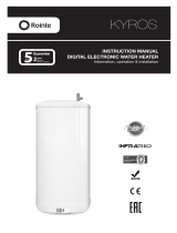
Hot water outlet Cold water inlet
Length “X”
1
2
3
To drain
Cold water suppy
Hot water outlet Cold water inlet
To drain
Cold water suppy
1
2
4
3
5
Scheme A Scheme B
When inlet pressure is less than 4 bar and expanded
hot water can be accommodated in the pipe work.
When inlet pressure is less than 4 bar but expanded
hot water cannot be accommodated in the pipe work.
DETAILS OF THE INSTALLATION
1
Expansion relief valve (included in the installation kit)**
2
Nearest cold water draw off (not supplied)
3
Service valve (not supplied)
4 Expansion vessel (included)
5 Check valve (included)
6
Pressure reducing valve (included)
MINIMUM LENGTH OF PIPE (X)
Capacity 15 mm pipe 22 mm pipe
10 L 2.7 cm 1.2 cm
15 L 4.2 cm 1.8 cm
* These images are only for reference. Check the Building Regulations (PART G) for specific details and accessories required to perform a proper installation. The Rointe
water heaters must be installed by an installer with a valid Unvented Water Heaters Installer certification.
**The installation kit is sold separately.
To drain
Cold water suppy
Hot water outlet Cold water inlet
1
2
4
3
5
6
Scheme C
When inlet pressure is greater than 4 bar.

7
• The xing of the safety return valve to cables greater than 10 mm in thickness is forbidden, as it could damage the valve
and render the water heater dangerous.
• The safety return valve and the pipe between the valve and the water heater must be protected against freezing.
During draining with the hose, the free end must always be open (not submerged). The hose should also be protected
against freezing.
The water heater tank is lled with water when you open the key in the cold water supply system and the hot
water faucet. After thr lling process, a constant ow of water must ow through the hot water tap. Once this
happens, the hot water tap can be closed.
When you want to empty the water heater tank, you must rst cut o the power supply.
Drainage procedure for above sink installation of the water heater:
1. Disconnect the water heater from the electric current.
2. Close the cold water supply tap
3. Open the hot water supply tap.
4. The water tap must be opened to drain the water from the water tank. If there is no such outlet pipe, the
water can be drained as follows:
• Discharge the water from the water heater by raising the recoil lever of the safety valve.
• The water can be drained directly from the inlet pipe of the water tank that has been disconnected.
IMPORTANT: When emptying the water heater, take measures to avoid damage caused by water ow
Drainage procedure for below sink installation of the water heater:
1. Disconnect the water heater from the electric current.
2. Close the cold water supply tap.
3. Remove the water connection accessories from the water heater.
4. Remove the thermos from point of installation. Rotate it so that the outlets are oriented downwards and
pour the water into a container. Wait until all the water drains from the water heater.
If the pressure in the water network exceeds the amounts indicated in section 1, it is necessary to install a
pressure reduction valve, otherwise the water heater will not work properly. Rointe does not assume any
responsibility for problems arising from incorrect use of the water heater.
4.3. Electrical ttings
The electrical ttings must be tted to the product. If not, the guarantee will be null and void.
4.4. Pressure reducing valve
The pressure reducing valve should be installed in the cold water supply to the water heating unit
with the arrow pointing in the direction of water ow as shown in Figure 2 . This can be connected to a
maximum supply pressure of 0.9 MPa.

8
4.5. Expansion relief valve
This must be installed between the pressure reducing valve and the water heating . No other valve
should be tted between this valve and the cylinder. The expansion relief valve contains a non
return valve.
4.6. Expansion vessel
The expansion vessel MUST be tted to the safety group. The expansion vessel MUST be positioned
with the entry point at the bottom
IMPORTANT: Regular checks must be carried out to ensure that the expansion vessel is correctly
pressurised to 0.15 or 0.3 MPa at all times.
4.7. Tundish
The tundish must not be positioned above or in close proximity to any electrical current carrying
devices or wiring.
4.8. Discharge arrangement
The tundish must be installed in a position so that it is clearly visible by the user. In addition, the discharge
pipe from the tundish should terminate in a safe place where there is no risk to persons in the vicinity of the
discharge, be of metal and:
4.8.1. Be at least one pipe size larger than the normal outlet size of the safety device unless its total equipment
hydraulic resistance exceeds that of a straight pipe 9m long, i.e. discharge pipes between 9m and
18m equivalent resistance length should be at least two sizes larger then the normal outlet size of the
safety device, between 18m and 27m at least three sizes larger and so on. Bends must be taken into
account in calculating the ow resistance. Refer to Figure 3, Table 1 and Calculated Example 1.
4.8.2. Have a vertical section of pipe at least 300 mm long below the tundish before any elbows or bends
in the pipework.
4.8.3. Be installed with a continuous fall.
4.8.4. Have discharges visible at both tundish and the nal point of discharge, but where this is not
possible or practically dicult, examples of acceptable discharge arrangements are:
– Ideally below a xed grating and above the water seal in a trapped gully.
– External surfaces such as car parks, hard standings, grassed areas, etc.) are acceptable providing
that where children play or otherwise come into contact with discharges, a wire cage or similar
guard is positioned to prevent contact whilst maintaining visibility.
– Discharge at high level, e.g. into a metal hopper and metal down pipe with the end of the
discharge pipe clearly visible (tundish visible or not) or onto a roof capable of withstanding high
temperature discharges of water and 3 m from any plastic guttering system that would collect
such discharges (tundish visible).

9
– Where a single pipe serves a number of discharges such as in blocks of ats, the number served
should be limited to not more than six systems so that any installation discharging can be traced
reasonably easily. The single common discharge pipe should be at least one pipe size larger than
the largest individual discharge pipe to be connected. If unvented hot water storage systems are
installed where discharges from safety devices may not be apparent (i.e. in dwellings occupied
by blind, or disabled people), consideration should be given to the installation of an electrically
operated device to warn when discharge takes place.
WARNING: The discharge will consist of scalding water and steam. Asphalt, roong felt and nonmetallic
rainwater goods may be damaged by such discharges.
Figure 3 - Typical discharge pipe arrangement.
SIZING OF COPPER DISCHARGE PIPE “D2” FOR COMMON TEMPERATURE
RELIEF VALVE OUTLET SIZES
Valve outlet size
(diameter,
inches)
Min size of
discharge pipe
D1 (mm)
Min size of
discharge pipe
D2 from tundish
(mm)
Max resistance
allowed, expressed
as a length of straight
pipe, i.e. no elbows or
bends
Resistance
created by each
elbow or bend (m)
15
22
28
35
up to 9
up to 18
up to 27
0.8
1.0
1.4
22
28
35
42
up to 9
up to 18
up to 27
1.0
1.4
1.7
28
35
42
54
up to 9
up to 18
up to 27
1.4
1.7
2.3

10
Calculated Example 1
The example below is for a 1/2” diameter temperature relief valve with a discharge pipe (D2) having 4
22mm elbows and a length of 7m from the tundish to the point of discharge.
The maximum resistance allowed for a straight length of 22mm copper discharge pipe (D2) from a 1/2”
diameter temperature relief valve is 9.0m.
Subtract the resistance for 4 x no 22mm elbows at 0.8m each = 3.2m.
Therefore, the maximum permitted length equates to: 5.8m.
5.8m is less than the actual length of 7m, therefore, calculate the next largest size.
Maximum resistance allowed for a straight length of 28mm pipe (D2) from a 1/2” diameter temperature
relief valve equates to: 18m.
Subtract the resistance for 4 No 28mm elbows at 1.0 each = 4m.
Therefore the maximum permitted length equates to: 14m.
As the actual length is 7m, a 28mm diameter copper pipe will be satisfactory.
4.9. Electrical connections
Before turning on the water heater, ensure it has been correctly installed and is full of water.
A1 / L
A2 / L
B1 / N
B2 / N
T2
S
T1
R
1
2
001
s
L1
Models supplied with a power cord with a plug must be plugged into a power outlet. The water heater can be
disconnected from the mains by unplugging it.
IMPORTANT: The outlet must be connected to a separate circuit provided with a safety mechanism. It must
be grounded.
For models equipped with a power cord without a plug, the appliance must be connected to an individual
electrical circuit of xed installation, equipped with a safety device with a nominal electrical current of 16A
(20A for power> 3700W). The connection must be constant (without a plug). The electrical circuit must be
equipped with a safety device and with a built-in mechanism that ensures the separation of all the poles in
case of type III overvoltage.
• Brown insulation cable to the phase cable of the electrical installation (L).
• Blue insulation cable to the neutral cable of the electrical installation (N).
• Yellow-green insulation conductor cable, to the protective cable of the electrical installation.
5. OPERATION
When you have performed the instructions described in section 4 above, you can start using the water heater
(which has an indicator light)
1
.
The indicator light is turned on when the water heater is connected to heat the water. The indicator light turns

11
o when the water reaches the selected temperature and indicates that the water heater is not in operation
and is no longer heating water.
Ignition switch with 2 positions
3
:
• Position 0 = OFF. The water heater is not active and does not heat water.
• Position I = ON. The water heater is regulated automatically by the thermostat positions
4
.
Control of the thermostat with 5 positions
4
:
• Anti-Frost Position : set the thermostat at this point for a minimum level of water heating. In this
mode, the water heater switches on when the temperature of the water contained in the water tank
falls below 5ºC. It is suitable in cases of low potential water temperature.
NOTE: In this setting, the water heater maintains a temperature that does not allow the water to freeze. The power
supply for the water heater must be activated and the water heater switched on. The safety valve and the pipes must
be protected against freezing.
In the event that the power supply is interrupted for any reason, there is a danger that the water in the tank will
freeze. Therefore, it is recommended to drain the water from the water heater during long absences.
• Position I (summer mode): The thermostat is in economical mode for low water temperature and
low power consumption. This mode is suitable when high water temperature is not necessary.
• Position II (winter mode): The thermostat is in optimal mode, with higher water temperature values.
This mode is suitable for when high water temperatures are necessary.
• Position
e
(energy saving mode): During this operating mode the water reaches a temperature of
approximately 60ºC for reduced heat loss.
• Position III (maximum mode): The thermostat is set in maximum operating mode, with very high
values of energy consumption and with maximum water temperature levels (around 70ºC). This is the
most suitable mode when a large volume of water with a pleasant temperature is needed.
6. PROTECTION AGAINST MAGNESIUM ANODE OXIDATION
The magnesium anode protects the inner surface of the water tank against corrosion.
The magnesium anode will deteriorate over time and is subject to periodic inspections. Rointe/the
manufacturer recommends a periodic inspection of the magnesium anode by an authorised technician and
if appropriate, during the periodic prophylaxis of the water heater.
To replace the magnesium anode, please contact the Rointe Technical Service on 0203 321 5929.
7. PERIODIC MAINTENANCE
Under normal operating conditions, and with a high temperature on the surface of the electrical resistance,
lime scale deposits can often occur. This worsens the exchange of heat between the resistance and the water,
causing the resistance to overheat along with typical noises of boiling water. The thermostat will turn on and
o more frequently. It is possible to activate the protection mode to avoid overheating. Because of this, the
Rointe/manufacturer recommend preventive maintenance every two years by an authorised installer from
the Rointe Technical Service (please call 0203 321 5929).
This maintenance should include cleaning and inspection of the anode, which should be replaced when
necessary.

12
8. GUARANTEE
In this section, we hereby describe the guarantee conditions, which the buyer acquires, on buying this product
from ROINTE. These conditions comply with all the rights construed in the national legislation in force, as well
as any additional rights and guarantees, which are oered by ROINTE.
Any incident that you might detect in your ROINTE product can be sorted by the product seller or quickly by
the manufacturer. Please contact ROINTE by telephoning 0203 321 5929 for Technical Support. Alternatively,
you can email ROINTE at suppor[email protected], through which we will instruct you on how to solve the
incident.
You will need the product reference, serial number, date of purchase and the nature of the failure to
contact us to improve the warranty. Also attach a copy of the product purchase invoice.
8.1. ROINTE guarantees that there are no material defects of design or manufacture at the time of original
acquisition and guarantees the inner steel cylinder for a period of 24 months and any electronic and electrical
components for 24 months, provided that they have not been modied in any way.
8.2. If during the guarantee period, the product does not work correctly under normal use, and any design,
material or manufacturing defect is found, ROINTE will repair or substitute the product as it may see t, in
accordance with the terms and conditions as follows:
8.2.1. The guarantee is only applicable if the original guarantee is issued by the seller and when the said
guarantee is lled in correctly including product reference, series number (marked on the product’s label
indicating technical features), purchase date and the seller’s stamp, and either registered on our website at www.
rointe.co.uk or returned completed to ROINTE within 90 days of installation. ROINTE reserves the right to reject
the guarantee service when this information has been removed or modied after the original product purchase.
8.2.2.1. Damage caused by negligence and/or misuse of the product, i.e. used for other purposes that
are not construed as its normal use or for not respecting the instructions of use and maintenance given by
ROINTE as well as incorrect installation or use of the product that may not comply with the current technical
standards of safety.
8.2.2.2. Corrosion of any part of the product caused by direct exposure to salt water. When the product is
installed no more than 200m from the coast the guarantee for damages caused by corrosion the period will
be reduced by 50%.
8.2.2.3. Any unauthorised modication of the product or repairs of the product carried out by third parties
or unauthorised technicians or opening of the product by third parties or unauthorised people.
8.2.2.4. Any accidents that are deemed outside the control of ROINTE, such as (but not limited to): lightning,
res, oods, natural disasters, public disorder, atmospheric or geologic phenomena etc.
8.2.2.5. Faults that result from an incorrect installation. Guidance can be found within the recommendations
for installation, by Rointe and in the installation manual. If in doubt, please contact ROINTE.
To clean the appliance, use a damp cloth. Do not use abrasive cleansers or those containing solvents. Do not
pour water over the water heater.
ROINTE reserves the right to modify the characteristics and specications of its products without prior notice.
ROINTE is not responsible for any consequences arising should the instructions contained in this manual not
be followed.

13
8.2.2.6. Aesthetic wear and tear produced by use, the cleaning of lime scale accumulation, revision and
substitution of the magnesium anode as well as other operations of maintenance of the product. Such repairs
will be charged to the user.
8.2.2. Any repairs or substitutions covered under this guarantee must be parts that are functionally equivalent.
The defective parts or parts removed or replaced shall become the property of ROINTE.
8.2.3. The product must be installed in a way that allows access for our technicians should they need to gain
access to the product for repair or maintenance. The user/client is responsible for any costs or organisation
required to provide access to the products for their repair and/or substitution.
8.2.4. The product has been installed indoors, in a frost free environment and has solely been used for the
purpose of heating potable water that complies with current (at time of installation) regulations and standards
and is not fed with water from a private source.
8.2.5. The product has not been subjected to excessive pressure or electrolytic actions from dissimilar
materials or attack from salt deposits.
8.3. The Technical Service department of ROINTE will advise you if you need to purchase any parts not covered
under the guarantee or out of guarantee.
8.4. This guarantee will be null and void if the product: has been manipulated, modied and/or repaired in any
way and/or by unauthorised persons. This guarantee will also be void if the product is not correctly installed.
8.5. This guarantee is not transferable and does not include claims due to frost or limescale damage.
8.6. Proof of purchase will be required to ROINTE for any claim.
8.7. This guarantee does not aect your statutory rights.
8.8. This guarantee does not aect the buyer’s legal rights stipulated in the current national legislation, nor
aects those rights against the distributor or installer that could come forth in compliance with the purchase
contract.
8.9. In the absence of a national legal legislation applicable, this guarantee shall prevail and may be construed
as the buyer’s only protection. ROINTE, its oces, distributors and installers may not be held responsible
for any accidental damage that emerges due to infringement of any rules implicitly related to this product.
9. EUROPEAN DIRECTIVE (WEEE) 2012/19/UE
Under the European Directive 2012/19/UE on Waste Electrical and Electronic Equipment (WEEE), the
product cannot be disposed in the usual council bins and containers. They must be separated to
optimize the recovery and recycling of all of the components and materials and reducing the impact
to human health and the environment. The symbol of the container crossed out over a horizontal line
is marked on all of ROINTE products to remind the consumer of the obligation to separate them on
disposal. The consumer should contact the local authority or original point of sale to learn more about
the correct disposal of this product.

14
MODELS
VWI010DHWD4 VWI015DHWD4 VWI010DHWU4 VWI015DHWU4
Volume (L) 10 15 10 15
Nominal power (W) 1,500 1,500 1,500 1,500
Outlet Bottom Bottom To p Top
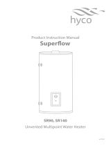
DIMENSIONS
Width x height x depth (mm) 372 x 406 x 257 372 x 406 x 324 372 x 406 x 257 372 x 406 x 324
Distance between connections
(mm)
100 100 100 100
CHARACTERISTICS
Empty weight (kg) 7.6 9.4 7.6 9.4
100% capacity weight (kg) 17.6 24.4 17.6 24.4
Water connections (inches) 1/2” 1/2” 1/2” 1/2”
Finishes White RAL 9016 (tank) || Black RAL 9005 (control panel)
EAN CODE 8436045913159 8436045913166 8436045913616 8436045913623
406 mm
372 mm
257 mm 324 mm
406 mm
372 mm
257 mm 324 mm
TECHNICAL INFORMATION
Submerged copper heating element
Enamelled steel tank
Magnesium anode protector
CFC-free polyurethane insulation foam
External casing in ABS
Maximum working pressure (bars) 8
Protection Grade IPX4
Energy Classication B
FUNCTIONS
External thermal regulator dial
INSTALLATION
Installation position Vertical
Safety valve
SAFETY
Safety thermostat
REGULATIONS & GUARANTEES
2004/108/CE Electromagnetic comp.
2006/95/CE Low voltage directive
Guarantee 2 years
10. DIMENSIONS & TECHNICAL CHARACTERISTICS

15
CERTIFICATE OF GUARANTEE
Cut along the dotted line
In the event of any defect being detected in the product within the period of guarantee, you must ll in the below Certicate
of Guarantee and send it to us stamped together with a copy of the sales invoice via email to suppor[email protected]
or to the following postal address: INDUSTRIAS ROYAL TERMIC, S.L., C/E, Parcela 43, 30140 Santomera (Murcia, Spain).
CERTIFICATE OF GUARANTEE
REFERENCE:
Nº SERIES:
PURCHASE DATE:
USER:
HOME ADDRESS:
TOWN: POSTCODE:
COUNTY:
COUNTRY:
TELEPHONE: EMAIL:
SELLER’S STAMP:
NB: This certicate of Guarantee MUST be completed in full in order to obtain guarantee rights. The purchase date and seller’s stamp are
compulsory. Please attach a copy of your sales invoices. In addition, for new constructions include the Certicate of First Occupation.

16

17
NOTES

18
NOTES

19

20
Rointe France
6 Rue Duret,
75116 Paris
T. (FR) 1 73 05 70 01
www.rointe.fr
Rointe UK & Ireland
Catalyst House, 720 Centennial Court,
Centennial Park, Elstree, Herts, WD6 3SY
T. (UK) 0203 321 5928
T. (IE) 015 530 526
www.rointe.co.uk
www.rointe.ie
Rointe Spain & Portugal
P.I. Vicente Antolinos C/ E, parc. 43
30140 Santomera (Murcia)
T. (ES) 902 158 049
T. (PT) 221 200 114
www.rointe.com
www.rointe.pt
Compact digital electric D.W.H. heater
Venice
-
 1
1
-
 2
2
-
 3
3
-
 4
4
-
 5
5
-
 6
6
-
 7
7
-
 8
8
-
 9
9
-
 10
10
-
 11
11
-
 12
12
-
 13
13
-
 14
14
-
 15
15
-
 16
16
-
 17
17
-
 18
18
-
 19
19
-
 20
20


Rointe VENICE Owner's manual
- Category
- Water heaters & boilers
- Type
- Owner's manual
Ask a question and I''ll find the answer in the document
Finding information in a document is now easier with AI
Related papers
-
 Rointe Geneva Owner's manual
-
Rointe Rome connected Owner's manual
-
 Rointe Siena Owner's manual
-
 Rointe VENICE Owner's manual
-
 Rointe AIR Control Owner's manual
-
 Rointe Basic Control remote Owner's manual
-
 Rointe D Series Owner's manual
-
 Rointe Capri Owner's manual
-
 Rointe Kyros Owner's manual
-
 Rointe Sygma Owner's manual


Other documents
-
Atlantic VERTIGO 841258 Operating instructions
-
ProFlo PFXT5 Installation guide
-
Santon Aquaheat AH30V Installation And User Instructions Manual
-
Inalsa PSG 25GL User manual
-
Ariston Unvented Hot Water Storage Cylinders User manual
-
Ortech HVAC User manual
-
 Hyco SR140 User manual
-
Heatrae Sadia MULTIPOINT 100 Fitting Instructions And User Manual
-
Bradford White RE2H80T10 User manual
-
 Hyco PF80S Product Instruction Manual

