Page is loading ...

1080P
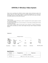
HDMI to 3GSDI Scaler
GEF-HD-2-3GSDIS
User Manual
www.gefenpro.com

ASKING FOR ASSISTANCE
Rev A8
Technical Support:
Telephone (818) 772-9100
(800) 545-6900
Fax (818) 772-9120
Technical Support Hours:
8:00 AM to 5:00 PM Monday through Friday, Pacifi c Time
For 24 / 7 support, see the back of the product for the support number
Write To:
Gefen, LLC.
c/o Customer Service
20600 Nordhoff St
Chatsworth, CA 91311
www.gefenpro.com
Notice
Gefen, LLC reserves the right to make changes in the hard ware, packaging, and
any accompanying doc u men ta tion without prior written notice.
HDMI to 3GSDI Scaler is a trademark of Gefen, LLC
HDMI, the logo, and High-Defi nition Multimedia Interface are
trademarks or registered trademarks of HDMI Licensing in the United States and
other countries.
© 2012 Gefen, LLC. All rights reserved.
All trademarks are the property of their respective owners.

CONTENTS
1 Introduction
2 Operation Notes
3 Features
4 Front Panel Layout
5 Front Panel Descriptions
6 Back Panel Layout
7 Back Panel Descriptions
8 Connecting The HDMI TO 3GSDI Scaler
8 Wiring Diagram
9 IR Remote Control
10 IR Remote Control Installation
11 IR Remote Control Confi guration
12 Menu System
12 General Menu
13 Patterns Menu
13 Output Menu
15 Input Menu
16 Picture Menu
18 Layout Menu
18 Aspect Menu
20 RS-232 Serial Interface
21 RS-232 Serial Control
34 Supported Video and Graphics Formats
37 Rack Mount Safety Information
38 Mounting Plate Installation
39 Appendix A
40 Specifi cations
41 Warranty

1
INTRODUCTION
Congratulations on your purchase of the HDMI to 3GSDI Scaler. Your complete
satisfaction is very important to us.
GefenPRO
In the realm of video distribution, certain features are invaluable in a commercial
or broadcast environment. Accommodations such as a build-in power supply
and fl at black rack-mount enclosures set GefenPRO apart from our traditional
products. Complex distribution units allow for professional DVI, 3G-SDI, and
HDMI signals to be routed and converted easily and seamlessly, while being
backed up by a renowned and dependable technical support team. Gefen invites
you to explore the GefenPRO product line and hopes that you fi nd the solution
that fi ts your needs.
The GefenPRO HDMI to 3GSDI Scaler
The GefenPRO HDMI to 3GSDI Scaler converts from HDMI source to single
link or dual link SDI formats on the output. Resolutions scaled up to 1080p,
1920x1200 and 2K with genlock and up to 8 channels of audio is supported.
The built-in S/PDIF audio output can be used to send digital audio to a
separate A/V receiver. This product uses the VXP scaler which provides high-
performance scaling plus additional features: Adaptive video interlacing with edge
interpolation, advanced noise reduction, alpha blending, image enhancement,
and a fully-integrated menu system. This product supports SDI, HD-SDI, and
3G-SDI SMPTE 425-A and 425-B formats. The GefenPRO HDMI to 3GSDI
Scaler provides superior 3G-SDI video packaged in a single rack mount unit with
an internal power supply.
How It Works
Connect a Hi-Def source to the GefenPRO HDMI to 3GSDI Scaler with the
supplied HDMI cable. Connect the 3G-SDI device to the BNC video connectors
on the output. Use another coax cable to connect an external clock to the
Reference-In BNC connector. Connect a digital audio cable between the S/
PDIF connector on the product and the A/V receiver. Apply power to the source
and 3G-SDI device and apply power to the product. The Hi-Def source will be
converted to 3G-SDI. Use the IR remote control unit to navigate the built-in menu
system to control the scaling features on the 3G-SDI output.

OPERATION NOTES
2
READ THESE NOTES BEFORE INSTALLING OR
OPERATING THE HDMI TO 3GSDI SCALER
• The built-in GUI (Graphical User Interface) or On-Screen Display (OSD)
provides convenient operation of the Scaler. The supplied IR Remote
control operates the OSD. See pages 12 - 19 for details on the OSD
functions.
• The IR Remote Control unit’s IR channel must be identical to that of the
Scaler. See page 31 for details on confi guring the IR Channel on the HDMI
to 3GSDI Scaler.
• The HDMI to 3GSDI Scaler supports many input and output resolutions. For
a complete list of supported formats, see pages 34 - 35.
• Supports SMPTE standards 259M, 292M, SMPTE 274M, SMPTE 296M,
ITU-R BT.656 and ITU-R BT.601. Handles 3G-SDI SMPTE 425-A and 425-B
/ formats 1080P 50/59.94/60.
• Internal software (fi rmware) may be upgraded via the built-in Serial or USB
ports. Note that software updates performed on the USB port will be quicker
due to its higher data transfer rate.

3
FEATURES
Supported HDMI Features:
• 225 MHz Video Bandwidth
• 10-bit Deep Color
• x.v.Color
• Up to 7.1 channels of LPCM
• Dolby Digital® and DTS™ encoded audio
Features:
• Supports resolutions up to 1080p, 1920 x 1200, and 2K
• Frame rate conversion
• Supports black burst (bi-level sync) and tri-level sync genlock
• 3G-SDI (SMPTE 424M/425M, up to 3.0 Gbps)
• HD-SDI (SMPTE 292M, up to 1.485 Gbps)
• SDI (SMPTE 259M, up to 360 Mb/s)
• Supports 3G-SDI SMPTE 425-A and 425-B (4:2:2 only)
• Advanced noise reduction and detail enhancement
• Fully integrated sprite based multi-plane OSD controller
• Pattern generation of color bars, and cross-hatch patterns
• Four aspect ratio modes (Full Screen, Panoramic, Letter/Pillar Box, Extract/
Crop)Monitor Supported Mode disables incompatible menu choices
• Film Mode (produces a progressively scanned output image from an
interlaced scanned input image accounting for cadence (e.g. 3:2 / 2:2 pull-
down)
• Confi guration of clean aperture size and position
• Built-in on-screen display (OSD) menu system
• Controlled via IR remote or RS-232 commands
• Field-upgradeable fi rmware
• Rack-mountable
Package Includes
(1) GefenPRO HDMI to 3GSDI Scaler
(1) 6 ft. Locking HDMI Cable (M-M)
(1) IR Remote Contol
(1) AC power cord
(1) Set of Rack Ears
(1) User Manual

4
PANEL LAYOUT
Front Panel
1 2 3

5
PANEL DESCRIPTIONS
Front Panel
1 IR Window
Receives signals from the IR Remote Control unit.
2 3GSDI Indicator
This LED will glow blue when 3GSDI signals are detected on the output.
3 Power Indicator
This LED will glow red when the unit is powered.

6
PANEL LAYOUT
Back Panel
1 4 6
753 8
10
2 9

7
PANEL DESCRIPTIONS
Back Panel
1 RS232 / 422
Connects to an RS-232 control device. The HDMI to 3GSDI can be controlled
remotely using this port. See page 20 for more information.
2 USB In
This high-speed USB port is used to update the fi rmware on the Scaler.
3 Ref In
Connects to a reference (clock) signal. Bi-level (Black Burst) and tri-level sync
are supported.
4 Coax Out
Connect a coax cable from this S/PDIF port to an amplifi er or other A/V device.
Up to 5.1 channels of digital audio are supported.
5 HDMI In
Connect a Hi-Def source to this HDMi input.
6 Out A
Connect an SDI / HDSDI / 3GSDI monitor to this BNC connector.
7 Out B
Use Out B in conjunction with Out A when running dual link 1080p. If dual link is
not required, Out B also serves as a mirrored output.
8 Power Switch
Turn the power ON or OFF using this switch.
9 Fuse Drawer
The power receptacle houses a fuse drawer which contains one 250V fuse.
10 110 / 220 V AC Power Receptacle
Connect the included AC power cord from this receptacle to an available
electrical outlet.

8
CONNECTING THE HDMI TO 3GSDI SCALER
How to Connect the HD to 3GSDI Scaler
1. Connect a HI-Def source to the HDMI In port on the back of the HDMI to
3GSDI Scaler using the included HDMI cable.
2. Connect the Out A port on the back of the Scaler to the 3GSDI destination.
The 3GSDI destination cab be mirrored by connecting a cable from the
Out B port.
In order to output dual link 1080p, when using HD-SDI, both Out A
and Out B must be connected, simultaneously, to the destination.
3. Connect a coax cable from the S/PDIF output to an external amplifi er.
4. Connect the included AC power cord to the power receptacle on the rear
panel of the HDMI to 3GSDI Scaler and connect the opposite end of the
cable into an available electrical outlet.
5. Power the HDMI to 3GSDI Scaler by pressing the power switch on the rear
of the unit.
Wiring Diagram for the HDMI to 3GSDI Scaler
Audio Receiver
3G-SDI Display
3G-SDI Display
Clock Generator
HDMI Source
Scaler
GEF-HD-2-3GSDIS
0
0:0 0:0 0
SDI CABLE
COAX AUDIO CABLE
HDMI CABLE
Attention: This product should always be connected to a grounded
electrical socket.

9
IR REMOTE CONTROL
RMT-8HDS-IR
1. LED indicator - glows bright orange whenever a key is pressed, indicating
the transmission of an IR command to the Scaler.
2. The ENTER button activates a selected menu option in the On-Screen
Display.
3. LEFT direction key for menu navigation within the On-Screen Display.
4. DOWN direction key for menu navigation within the On-Screen Display.
5. Source - Cycles between available input sources. The selectable inputs are
3GSDI Input 1 and 3GSDI Input 2. Press once for Input 1; twice for Input 2.
6. Output - Cycles through the available output resolutions. See pages 34 - 35 for
a list of output resolutions.
7. Menu - Displays the On-Screen Display menu system for control of the
Scaler.
8. RIGHT direction key for menu navigation within the On-Screen Display.
9. UP direction key for menu navigation within the On-Screen Display.
1
2
3
4
5
9
8
7
6

IR REMOTE CONTROL INSTALLATION
10
Installing the RMT-8HDS-IR Battery
1. Remove the battery cover on the back of the IR Remote Control unit.
2. Insert the included battery into the open battery slot. The positive (+) side of
the battery should be facing up.
3. Replace the battery cover.
The Remote Control unit ships with two batteries. One battery is required for
operation and the other battery is a spare.
CAUTION: Risk of explosion if battery is replaced by an incorrect
type. Dispose of used batteries according to the instructions.
Battery Slot

11
IR REMOTE CONFIGURATION
How to Resolve IR Code Confl icts
In the event that IR commands from other remote controls interfere with the
supplied IR Remote Control unit, changing the IR channel on the IR Remote
Control unit will fi x the problem. The IR Remote Control unit has a bank of DIP
switches used for setting the IR channel.
The DIP switch bank is located underneath the battery cover.
1 2
1 21 2
1 2
Remote Channel 2:
Remote Channel 0:
Default
Remote Channel 1:
Remote Channel 3:
Exposed DIP Switch
bank between the
battery chambers.
It is important that the IR channel on the Remote Control unit, matches the IR
channel set on the HDMI to 3GSDI Scaler. For example, if both DIP switches
on the IR Remote Control unit are set to IR channel 0 (both DIP switches down),
then the HDMI to 3GSDI Scaler must also be set to IR channel 0 (see page 31).

12
MENU SYSTEM
General Menu
Information
To access the General Menu, press the Menu button on the IR Remote Control
Unit. The General Menu will be the fi rst menu displayed on contains information
about the Scaler:
• Host Firmware Version
• Kernel Version
• Confi guration Version
• FPGA Version
• Remote Channel
General > Language
From the General Menu, press the ▼ button on the IR Remote Control Unit.
Select the Language using the ► and ▼ buttons on the IR Remote Control Unit.
Press the Menu button to exit the menu.
• English
• French
General > Save Confi guration
The Save Confi guration feature is used to save the current confi guration of the
Scaler. Once the current confi guration is saved, these settings will be restored
each time the Scaler is powered.
This function will overwrite any previously saved confi guration,
including the factory default settings. To restore the factory default
settings, press the following buttons in order: Left, Right, and OK
buttons. Do not depress all three buttons simultaneously.

13
MENU SYSTEM
General > Restore Default Confi guration
Restores the Scaler to factory default settings. Use this feature to restore default
confi gurations if they have been overwritten by using the Save Confi guration
function.
Patterns Menu
Patterns > Color Bars
Produces a color bar pattern, similar to a standard SMPTE bar pattern used for
color calibration.
Patterns > Hatch Pattern
Produces a cross hatch pattern. This pattern can be used for “pin cushion”
testing (curvature of the image on the screen) or color convergence / divergence.
When a pattern is produced, the current video image will be masked.
Output Menu
The 3GSDI output signal can be confi gured from the Output menu. The Output
menu controls several functions, such as resolution, link confi guration (single link
or dual link), genlock reference, and genlock offset.
Output > Output Format
Selects the output resolution. See pages 34 - 35 for details on available output
formats.

14
MENU SYSTEM
Output > Link Confi guration
Selects the link confi guration in respect to color space. When using dual link SDI
or HD-SDI input, YCbCr or RGB can be selected. If 3G-SDI is used, A or B (4:2:2
only) can be selected.
• Single Link YCbCr 4:2:2 (SD/HD/3G)
• Single Link 1080p (3G Level B)
• Dual Link YCbCr (HD)
• Dual Link RGB (HD)
• Dual Link 1080p / 576p / 480p (HD)
Output > Genlock Reference
This option enables or disabled the automatic genlock mode.
• Off
Disabled genlock
• Video Input
Uses the video input as the reference clock.
• Ref Input
Uses the clock attached to the Ref In connector on the back of the unit.
Output > Genlock Offset
This option provides the option to adjust the output lines and output pixels.
• Output Lines
• Output Pixels

15
MENU SYSTEM
Input Menu
Input > Input Video Format
Selects the resolution and timing of the input format. By default, this is set to
Auto Detect which automatically senses the resolution and timing of the input
signal. The available resolutions under this menu are in SD and HD format.
Input > Graphic Format
Selects the resolution and timing of the input format. By default, this is set to
Auto Detect which automatically senses the resolution and timing of the input
signal. The available resolutions under this menu are in VESA format.
Input > Clean Aperture
Allows adjustment of the input signal position. The clean aperture parameters
allow an area within the production aperture to be defi ned. The minimum clean
aperture size is 0 pixels by 0 lines.
• Horizontal Size
Adjusts the horizontal size of the image.
• Vertical Size
Adjusts the vertical size of the image.
• Horizontal Position
Adjusts the horizontal position of the image.
• Vertical Position
Adjusts the vertical position of the image.
Input > Film Mode
Automatically detects repeated fi eld sequences present in interlaced signals,
such as: 50 Hz or 60 Hz fi eld sequences (no repeated fi elds), 60 Hz 3:2 pull-
down, including broken / edited sequence detection, 60 Hz 2:2: pull-down, 50 Hz
2:2 pull-down, and Freeze frame.
• Enable
• Disable

16
MENU SYSTEM
Input > Remote Channel
This option changes the IR channel of the HDMI to 3GSDI Scaler to one of 4
different settings between 0 and 3. When the remote channel of the Scaler is
changed, the DIP switches in the eight-button remote must be changed to the
corresponding IR channel in order to operate the Scaler (see IR Remote Control
Installation on page 10 for more information).
Input > Input Color Range
The RGB output color range may be changed/set to limited (16-235) or to full
(0-255).
• Auto
Uses the color range of the input signal.
• 16 - 235 (Pass through)
The input color range will be compressed from full-range (0 - 255) to limited-
range.
• 0 - 255 (Compress)
The output color range will be expanded from limited-range (16 - 235) to full-
range (0 - 255).
Picture Menu
Picture > Image Color
Allows individual adjustment of the Red, Green, and Blue color components,
brightness, and Black Level of the image.
• Red
Adjusts the saturation of the Red color component.
• Green
Adjusts the saturation of the Green color component.
• Blue
Adjusts the saturation of the Blue color component.
• Brightness Red
Adjusts the brightness of the Red color component.
• Brightness Green
Adjusts the brightness of the Green color component.
• Brightness Blue
Adjusts the brightness of the Blue color component.
• RGB/Y Output Offset
Adjusts the black level of the image.

17
MENU SYSTEM
Picture > Gamma Correction
• Default
Sets the default Gamma settings.
• sRGB
Gamma correction used with PCs, cameras, and printers.
• User Table
This option is used with a user Gamma LUT. See pages 38 for details on
using a Gamma Look Up Table.
• Custom Table
Use when defi ning a custom LUT. See pages 38 for details on using a
Gamma Look Up Table.
• Gamma Coeffecient
Adjusts the Gamma coeffecient in the range from 0.3 to 3.0. The default
Gamma value is 1.0.
When the Custom LUT (Look Up Table) is selected, the Gamma
coeffi cient is used to calculate a new Gamma LUT.
Picture > Detail Enhancement
These parameters processes the input data in either progressive or interlaced
format. Changes to the detail enhancement are implemented at the start of the
next frame of video. Both of these parameters can be adjusted within the range
or 0 - 100.
• Detail Enhancement
• Noise Threshold
Picture > Noise Reduction
This is an adaptive noise reduction function which processes the input data in
either progressive or interlaced format. Enabling the Noise Reduction to noisy
interlaced signals can optimize de-interlacer performance.
/