Page is loading ...

To insure proper installation in complete compliance with your warranty, we recommend installation by a professional installer.
Please use extreme care while unpacking and handling your GlassCrafters’ Mirrored Cabinet Accessory.
Report any damage immediately to our GlassCrafters customer service team at 800-233-7362,
Monday thru Friday from 8:00 am to 5:00 pm (EST)
Vertical LED Task Lights for Mirrored Cabinets
Installation Instructions
Congratulations on your purchase of Americas nest Accessories for Mirrored Cabinets by GlassCrafters, Inc.
World class engineering and state of the art design will enable you to enjoy your cabinet for many years to come.
We realize that the marketplace offers many choices and we thank you for selecting GlassCrafters for your Mirrored
Cabinet needs. The following instruction sheets are applicable for installation of this accessory on all Flat or Beveled
Frameless Mirror Cabinets, both 4” deep and 6” deep.
This accessory also may be added to any previously installed surface mounted GlassC rafters Mirrored Cabinet.
Patent Pending.
GLASSCRAFTERS, INC
193 Veterans Blvd., Carlstadt, NJ 07072
1+(800) 233-7362 (F) 1+(888) 233-7362
06/2016
1
36” High
Vertical Task LED Lights
(Mirrored Cabinet Sold Separately)
24” High
Vertical Task LED Lights
(Mirrored Cabinet Sold Separately)
30” High
Vertical Task LED Lights
(Mirrored Cabinet Sold Separately)
This unit’s electrical connections
must be made by a
Licensed Electrician in a
manner that conforms to the
National Electric Code.
WARNING
All GLASSCRAFTERS
Vertical LED Task Light Fixtures for Mirrored Cabinets
must be wired to a Class A 120V AC 15-20 Amp GFCI
circuit (Ground Fault Circuit Interrupter) when used in
bathrooms and all other locations
required by the National Electr ic Code.

2
Vertical LED Task Lights for Mirrored Cabinet
The following instruction sheets include the ALL FRAMELESS 24”, 30” AND 36” MODELS in both
4” deep and 6” deep Mirrored Cabinets.
WARNING
All GLASSCRAFTERS Vertical LED Task
Light Fixtures for Mirrored Cabinets must be
wired to a Class A 120V AC 15-20 Amp GFCI
circuit (Ground Fault Circuit Interrupter)
when used in bathrooms and all other
locations required by the
National Electr ic Code.
Index
LED Task Light Parts List for All Models...................3
Wiring Schematic .....................................................4
Determining the Rough Opening..............................5
Installing Vertical LED Task Lights on:
-- Surface Mounted Cabinet, 4” & 6” deep ..............6 & 7
-- Recessed Cabinet, 4” deep..................................8
-- Recessed Cabinet 6” Deep ................................9
-- Surface Mounted & Recessed Mirrored
Cabinet with Electric Option , 4” or 6” deep.........10
Optional Mirror Side Kit ...........................................11
Assembling Lights with Multiple Cabinets ................12
Door Installation .......................................................12-14
Limit Clip ..................................................................15
Warranty...................................................................16
Unpack all parts carefully and protect
components during installation.
Carefully review all parts and read the installation instruction
before you start.
SAVE THESE INSTRUCTIONS
FOR FUTURE REFERENCE
To insure proper installation in complete compliance with your
warranty, we recommend installation by a professional installer.
IMPORTANT
SAFETY INSTRUCTIONS
When using the Vertical ED Task Light , basic precautions should
always be followed, including the following:
Read all instructions before using.
DANGER –
To reduce the risk of electric shock:
1. Turn Power off at service panel before working on wiring.
2. DO NOT SPRAY LIQUID CLEANERS on the Vertical LED Task
Light. For cleaning, we recommend using “ammonia free” Sprayway
brand glass cleaner applied to a clean cloth.
WARNING –
To reduce the risk of burns, fire, electric shock, or injury to persons:
1. Use this Vertical LED Task Light only for its intended use as
described in these instructions. Do not use attachments not
recommended by the manufacturer.
2. Do not use outdoors.
SAVE THESE INSTRUCTIONS
Any servicing is to be performed by an authorized service
representative. The unit has no user serviceable parts.
A. Safety Glasses --
should be worn at all
times
B. Tape Measure
C. Level
D. #2 Phillips Head
Screw Driver
E. Power Screw Driver
Tools Required for Installation
GlassCrafters recommends the following tools to
properly and safely install your Vertical lights on a
Glasscrafters Cabinet.
Cleaning Recommendations:
Never use abrasive cleaners or cleaners
containing ammonia. This may cause
chemical damage to the mirror and void
the warranty.
For cleaning the mirror, we recommend
using ammonia free Sprayway brand glass
cleaner, which is available at a variety of
retail outlets.
www.spraywayinc.com/content/glass-cleaner
A Maximum of 4 interconnected units may be installed utilizing a
Class A 120V AC GFCI circuit. Each Vertical LED Task Light is
powered by a 12V driver and the assembled 2 fixture unit is rated to
draw 3± amps. Electric wiring must be by a licensed electrician.
Recessed or wall mounted installations should be performed by a
professional installer.

3
• Each Vertical LED Task Light is completely
assemble with factory installed 2 cabinet connectors,
1 Wire Bushing, 1 Wire Thru Bushing, 5 strips of LED
Lights and a 12 Volt Converter.
• Do not attempt to repair or change any connections
within the light fixture.
• For the 30” h and 36” h lights, the left or right side
fixture is clearly labeled in the package.
• The Vertical LED Task Lights are available for both
flat and beveled frameless mirrored cabinets.
Each installation package is supplied with two fixtures.
• 24” height sets are reversible for position, fits any width.
• For 30” and 36” height left and right are clearly labeled in the package, fits any width.
• Each Installation package comes with the two lights fully assembled with the cabinet connectors installed
and two installation packages with parts as shown here.
4” Installation Wood Screw (4)
#10-31 Screws (8)
Left
Not to Scale
Each pair of lights ships with one parts package.
Right
Not to Scale
Includes Wire Bushing
Top/Bottom
Plate Cover
Screw
Guide
Installation Parts Package
All wiring should be done by a
qualified licensed electrician.
NOTE: For Electric Wiring
Instructions for each type of
installation see pages 6-10.
Shown here is the side electric access hole for Vertical LED Task Light.
The dimensions indicate the set back from the finished surface of the access hole in
the stud, which must align exactly with the Plastic Bushing. Move the Wire Bushing
to this location for side access.
If the finished surface is to include tile or any decorative wall finishes, in
addition to the 1/2” sheetrock over the studs, then the center point for the 1 1/2” dia
access hole through the studs for the light fixtures is to be
located at a depth 1 3/4” from the final finished surface that includes the thickness
of those surface finishes such as tile, for both 4” & 6” recessed instalations.

4
ALL 120V WIRE TO BE 12/2 RX (MWB) GAUGE
WHEN USED with A GFCI RECEPTICLE CIRCUIT
12 VOLT LED POWER SUPPLY
PS 118
LED LIGHTING LED
ON
C
OV
12V
L1
WALL SWITCH
N
L
GND
GND
12 VOLT LED POWER SUPPLY
PS 118
LED LIGHTING LED
OV
12V
L1
N
N
L
GND
GND
GND
BLACK
WHITE
Left Side
Right Side
CIRCUIT
BREAKER
120 V AC
15 Amp
N
WARNING
IMPORTANT
SAFETY
INSTRUCTIONS
To reduce the risk of electric shock,
burns injury or fire follow these
precautions:
TO PREVENT SHOCK OR
ELECTROCUTION TURN POWER
OFF AT THE SERVICE PANEL
BEFORE WORKING WITH WIRING.
1. Install and use this cabinet
accessory in a household or
commercial residential setting.
2. Do not alter or add any features or
other appliance not recommended by
the manufacturer.
3. Do not alter the factory installed
wiring or any of its features or appurte-
nances.
4. This unit’s service wiring and
electrical connections must be made
by a Licensed Electrician in a
manner that conforms to the
National Electric Code.
5. The Vertical LED Task Light units
require a Class A 120V AC 15 Amp
circuit.
All installations must conform to the
National Electric Code.
GROUNDING: This product must be
connected to a grounded, metal
permanent wiring system or an
equipment-grounding conductor must
be run with the circuit conductors and
connected to the equipment terminal or
lead on this product.
VERTICAL LED TASK LIGHT
Unpack all parts carefully and protect parts during installation.
ON
C
WALL SWITCH
GND
BLACK
WHITE
Lighting Circuit Line Cable
BLACK
WHITE
12V LED Driver
GREEN
L
G
N
12V LED Driver
BLACK
WHITE
GREEN
L
G
N
ALL 120V WIRE TO BE 14/2 RX (MWB)
WHEN USED IN A LIGHTING CIRCUIT
Alternate Wiring Diagram from a Wall Switch
Standard Wiring Diagram from a Wall Switch

5
“RO” Rough Opening formula for Recessed Cabinets:
-- The model dimension of any single cabinet actually measures 5/8” less than the model size. (ie. 24” model height is actually 23 3/8”)
-- For added Lights Accessory increase the R.O. width by 4 3/4” for the two lights.
-- With the added Lights Accessory increase the R.O. width by 4 3/4” for the two lights.
Widths for any combination cabinets are the two specified widths less 5/8”. (The cabinet connector utilizes the second 5/8”.)
-- For Example: Model GC1630 at 14 3/8” wide, plus the 5/8” connector, combined with Model GC2430 at 22 3/8” = Rough Opening.
-- With the added Lights Accessory increase the R.O. width by 4 3/4” for the two lights
Height: overall cabinet height less 5/8” = R.O. Height. (LIGHT FIXTURE heights are the same as the cabinet height.)
2x4
Framing
Shown
PLUMB
LEVEL
Overlaps Finished
Surfaces 3/4”
Overlaps Finished
Surfaces 3/4”
Wall Switch
Service Wire
The recessed installation instructions in your cabinet manual contain the same Rough Opening dimensions.
WITH THE ADDITION OF THE TWO VERTICAL LIGHTS YOU MUST ADD 4 3/4” TO THOSE DIMENSIONS AS SHOWN IN THE TABLES BELOW.
YOU MAY ADD THE LIGHT FIXTURE TO SINGLE CABINETS OR TO COMBINATION CABINETS.
THESE FIXTURES MUST BE ON THE OUTSIDE EDGE OF THE ASSEMBLED CABINETS.
DO NOT ATTEMPT TO INSTALL ANY LIGHT FIXTURE BETWEEN CABINETS.
Add 4
3
/4” to the width for all Rough Openings and Framing
for Cabinets with Vertical LED Task Lights
Drill Rough Wiring access from the switch box to both
sides for each light xture.
• Standard back access is 3” above the base of the assem-
bled unit, and 1.5” from either the left or right side.
• Depending on the electrician’s service wiring plan this unit
may have alternate wring access from the top or the bottom
at the back of the unit and/or from the outside or inside
walls.
• The wire bushing in each fixture should be moved to the
access hole to be used.
• Allow 15” excess wire for pull through.
RECESSED MOUNT
Important:
Make sure you allow
for a minimum of
1” clearance above
any obstruction
such as faucets, etc.
Avoid installing light
xtures too close to
sinks
.
RECESSED MOUNTING -- Determining the Rough Opening “RO” Dimension
Framing in new construction should follow these dimensions. Standard 2x4 studs and 1/2” sheetrock are shown in the illustrations.
For 6” deep models, a semi-recessed installation is required. For fully recessed 6” deep models, 2x6 studs are required.
4 3/4” HAS BEEN ADDED TO ALL DIMENSIONS TO ALLOW FOR THE LIGHT FIXTURES
Model # R.O. 1 Cabinet 1 w/Vertical lights R.O. 2 Cabinets 2 w/Vertical lights R.O. Three (3) cabinets 3 w/Vertical lights
Width x Height Width x Height Width x Height Width x Height Width x Height Width x Height
GC1624 14 3/8”x23 3/8” 19 1/8”x23 3/8” 29 3/8”x23 3/8” 34 1/8”x23 3/8” 44 3/8”x23 3/8” 49 1/8”x23 3/8”
GC1630 14 3/8”x29 3/8” 19 1/8”x29 3/8” 29 3/8”x29 3/8” 34 1/8”x29 3/8” 44 3/8”x29 3/8” 49 1/8”x29 3/8”
GC1636 14 3/8”x35 3/8” 19 1/8”x35 3/8” 29 3/8”x35 3/8” 34 1/8”x35 3/8” 44 3/8”x35 3/8” 49 1/8”x35 3/8”
GC2030 18 3/8”x29 3/8” 23 1/8”x29 3/8” 37 3/8”x29 3/8” 42 1/8”x29 3/8” 56 3/8”x29 3/8” 61 1/8”x29 3/8”
GC2036 18 3/8”x35 3/8” 23 1/8”x35 3/8” 37 3/8”x35 3/8” 42 1/8”x35 3/8” 56 3/8”x35 3/8” 61 1/8”x35 3/8”
GC2430 22 3/8”x29 3/8” 27 1/8”x29 3/8” 45 3/8”x29 3/8” 50 1/8”x29 3/8” 68 3/8”x29 3/8” 73 1/8”x29 3/8”
GC2436 22 3/8”x35 3/8” 27 1/8”x35 3/8” 45 3/8”x35 3/8” 50 1/8”x35 3/8” 68 3/8”x35 3/8” 73 1/8”x35 3/8”
GC3630-TRI 35 3/8”x29 3/8” 40 1/8”x29 3/8” N/A N/A N/A N/A
GC4830-TRI 47 3/8”x29 3/8” 52 1/8”x29 3/8” N/A N/A N/A N/A
GC3636-TRI 35 3/8”x35 3/8” 40 1/8”x35 3/8” N/A N/A N/A N/A
GC4836-TRI 47 3/8”x35 3/8” 52 1/8”x35 3/8” N/A N/A N/A N/A
RECESSED MOUNTING -- Rough Opening:
Note: Cabinet installs over nished wall with sheetrock and/or tile
nishes completed. 3/4” Flange on all sides of the Light
Fixtures as joined to the cabinet will cover the remaining space
in the R.O.
NOTE: Tri-View Cabinets and Joined Cabinets with Vertical LED Task Lights that are wider than 32”
have reduced the light output in the center portion of the assembly.

6
Vertical LED Task Lights for Surface Mounted
4” deep Mirrored Cabinet
FOR INSTALLATION OF A SURFACE MOUNTED CABINET
BE SURE TO TURN OFF THE POWER AT THE SERVICE PANEL
BEFORE WORKING ON WIRING.
1. Install the rough service wiring from the switch box as lo-
cated in the wall near the final cabinet position. Rough wire
from the Switch Box to the general area for each light at the
measured and marked location for the cabinet installation.
2. Install the Glasscrafters, Inc. Mirrored Cabinet on the
finished surface following the manual instructions supplied
with the cabinet. Drill a 3/4” dial. hole 3” above the cabinet
base and 1” from the cabinet wall. Pull the rough wiring
through the wall.
3. To gain access to the
interior of the light
fixture to connect power
supply you must open
the fixture with these
steps:
--Remove Top & Bottom
plates with the two
screws located in the
rectangular part of the
plates.
--Remove the acrylic
diffuser by squeezing
from the narrow side
and pivoting it away
from the fixture.
--Unscrew the three
flathead stainless
screws holding the
Mounting Panel, the
panel with the mounted LED strips (the outside panel). Pivot
the Mounting Panel to the outside and disconnect the plug
that connects the 12V LED Driver box to the light strips and
set the LED Mounting Panel assembly aside.
Service Wire
Wall Switch
Mark the
Cabinet
Surface Mount
Location
Service Wiring
to Each Side
in approximate
location
for Light Fixtures.
Pull through
at least 15”
Service Wire
Step 1
BLACK
WHITE
12V LED DRIVER
GREEN
L
G
N
TERMINAL
BLOCK
SERVICE WIRE
Detail #1
Squeeze
Diuser and
Pivot away
from
Narrow side
Remove top
and
bottom Plates
NOTE: TAKE CARE IN HANDLING AND INSTALLING TO
AVOID DAMAGE TO MIRRORS. ALWAYS PLACE THE
MIRRORED CABINET ON A PADDED SURFACE TO
PROTECT GLASS.
SECTION VIEW OF A 4” SURFACE MOUNTED CABINET WITH
VERTICAL LED TASK LIGHTS.

7
4. Move the wire bushing to the wire entry holes you plan
to use. Insert the service wire through the wire bushing at
the selected locations and pull the service wire through.
Holding the fixture against the outer wall of the installed
cabinet align the two connecting brackets with the proper
holes in the cabinet wall and attach the fixture with the
four (4) #10-32 screws supplied. (Reminder: the 30” and
36” Vertical lights come marked as left and right. Keep the
parts for each light fixture separate until reassembly.
Repeat these steps for the opposite light fixture.
5. Trim the service wire leaving at least 6-8” of cable and
peel away the sheathing. Strip and insert the three wires in
the
terminal Block following the labels ”N” White (Neutral), “L”
Black (Live), ”G” Green (Ground). DO NOT ALTER ANY
OF THE FACTORY INSTALLED WIRING.
OPTIONAL SIDE MIRROR KIT (Pre-assembly)
6. Install the 2 Side Mirror Brackets on the outside face of
the Mounting Panel using the screws and Brackets in the
Side
Mirror Kit. (See page 11 for details.)
(Do not remove the paper covering the adhesive until you
are ready to install the Side Mirror in Step 9 (see page 11).
NOTE: 6” Deep Cabinets install surface mounted or
semi-recessed in the same manner except that the
Screw Guide should be moved to the 6” position as
shown on page 9.
7. To replace the LED Mounting Panel,
first reconnect the power cable from the
12V LED Drive Box to the LED Assembly.
Hold the LED Mounting Panel in place
and affix it using only the three stainless
screws provided. Replace the Diffuser
and the Top and Bottom Plates using only
the screws provided.
--Repeat the same steps for the light
fixture on the other side of the cabinet.
8. Complete the cabinet installation with the shelves and
door as per the cabinet
installation manual.
9. Install the Mirrored Side Kits on the outside of both fix-
tures following the instructions on page 11 and/or in the
Cabinet Manual.
Step 2, 3, 4
Stainless Steel Screws
Step 7

8
Vertical LED Task Lights for Recessed Mounted
4” Deep or 6” Deep Mirrored Cabinet
FOR INSTALLATION OF A RECESSED MOUNTED CAB-
INET BE SURE TO TURN OFF THE POWER AT THE
SERVICE PANEL BEFORE WORKING ON WIRING.
1. Adding the Vertical LED Task Lights to any cabinet in-
creases the width of the framed Rough Opening by 4 3/4”
(2 3/8” for each fixture on the left and right). Frame
according to the Cabinet Manual with this additional
dimension. (See page 5 for the modified Rough Opening
Dimensions.)
2. Install the rough service wiring from the switch as
located in the wall near the final cabinet position. Rough
wire from the Switch Box to the general area for each light
at the measured and marked location for the cabinet instal-
lation. Drill the wire access hole (1 1/2” dia) to align with
the selected access hole in the fixture.
Assemble the Cabinet with the Light Fixtures:
3. To install the light fixture on the cabinet and to connect
the power supply you must gain access to the interior of
the light fixture. Open the fixture with these steps:
-- Remove Top & Bottom plates with the two screws
located in the rectangular
part of the plates.
-- Remove the acrylic
diffuser by squeezing from
the narrow side and
pivoting it away from the
fixture.
-- Unscrew the three
flathead stainless screws holding the
outer Mounting LED Panel, the panel
with the mounted LED strips . Pivot the
outer Mounting Panel to the outside
and
disconnect the plug that connects the
12V LED Driver box to the light strips
and set the LED Mounting Panel
assembly aside.
4. Holding the inner wall panel of the fixture against the outer wall of
the cabinet align the two factory installed connecting brackets with the
proper holes in the cabinet wall and attach this part of the light fixture
with the four (4) #10-32 screws supplied. (Reminder: the 30” and 36”
Vertical lights come marked as left and right. Keep the parts for each
light fixture separate until reassembly.
Repeat these steps for the opposite light fixture.
BLACK
WHITE
12V LED DRIVER
GREEN
L
G
N
TERMINAL
BLOCK
SERVICE WIRE
Detail #1
SECTION VIEW OF A 4” RECESSED CABINET WITH VERTICAL LED TASK LIGHTS.
Squeeze
Diuser and
Pivot away
from
Narrow side
Remove top
and
bottom Plates
NOTE: TAKE CARE IN HANDLING AND
INSTALLING TO AVOID DAMAGE TO MIRRORS.
ALWAYS PLACE THE MIRRORED CABINET ON A
PADDED SURFACE TO PROTECT GLASS
.

9
INSTALLATION OF A 6” RECESSED CABINET
WITH VERTICAL LED TASK LIGHTS.
FOR INSTALLATION OF A RECESSED MOUNTED CABINET BE
SURE TO TURN OFF THE POWER AT THE SERVICE PANEL
BEFORE WORKING ON WIRING.
Adjustments for installation of a 6” deep cabinet:
Before installing the inside panel of the fixture on the cabinet,
move the Screw Guides to the pre-drilled holes toward the
back edge of the fixture. This will enable the Screw Guides to
align properly with the correct holes in the 6” cabinet walls.
SECTION VIEW OF A 6” RECESSED CABINET WITH VERTICAL LED TASK LIGHTS.
6. To Install the fully assembled cabinet with the two light
fixtures recessed in the wall you must complete the wiring
connections before reassembling the light fixtures.
NOTE: The fully assembled cabinet with two lights covers the
finished surfaces so all sheetrock, tile and any other wall
covering must be finished.
REMINDER: Install the recessed cabinet without the door.
a. Place the cabinet as assembled with the light fixture inner
panels installed on each side on a flat secure surface, cushioned
with a piece of carpet or a towel. Stand in a
secure position on the same level and directly in
front the finished opening.
b. Move the wire bushing to the wire entry holes
you plan to use. Insert the service wire through
the wire bushing at the selected locations and
pull the service wire through.
c. Trim the wire cable leaving at least 6-8” of
cable and peel away the sheathing. Strip and
insert the three wires in the Terminal Block
following the labels ”N” White (Neutral), “L” Black
(Live), ”G” Green (Ground). DO NOT ALTER
ANY OF THE FACTORY INSTALLED WIRING.
Repeat for the second light fixture.
d. To replace the outer Mounting Panel first re-
connect the power cable from the 12V LED Drive
Box to the LED Assembly. Hold the LED
Mounting Panel in place and affix it using only
the three stainless screws provided. Replace the
Diffuser and the Top and Bottom Cover Plates using only the screws
provided.
Repeat for the second light fixture.
Stainless Steel Screws
e. Lift and tip the cabinet up and into position within the finished
opening. Shim as need for level and plumb.
f. Insert the four installation screws provided (4”) from the
inside of the cabinet through the factory installed Screw Guides in the
fixture, which aligns with the pre-drilled hole in the center of the cabi-
net just above and below the cabinet’s hinge. Using the four 4” Instal-
lation screws provided, insert the secure into the framed recess.
7. Complete the cabinet installation with the shelves and door as per
the cabinet installation manual.
Detail 6e

OUTLET IN CABINET
ELECTRIC OPTION CABINET
SERVICE AS THRU-WIRE
FOR SHELF UNIT ONLY
SHELF
INSIDE
CABINET
SEPARATE
SERVICE
WIRE FOR
LIGHT
FIXTURE
CABINET
TERMINAL
BLOCK
WIRE
BUSHINGS
L
G
N
BLACK
WHITE
GREEN
L
G
N
GREEN
WHITE
BLACK
DRILL HOLE
1 1/2”
10
LED
DRIVER
OUTLET
IN
CABINET
CONNECTING
BRACKET
ELECTRIC OPTION SERVICE WIRE
SIDE ACCESS THROUGH VOID
BETWEEN CABINET & FIXTURE
SHELF
INSIDE
CABINET
SECOND
TASK LIGHT
WIRING
MAY GO OVER
OR UNDER
CABINET
FOR ACCESS
TASK LIGHT
SERVICE
WIRING
WALL SWITCH
BOX
LIGHTING
CIRCUIT
WIRE
LIGHT
TERMINAL
BLOCK
DIFFUSER
WIRE
BUSHING
FINISHED WALL SURFACE
SCREW
GUIDE
OUTER PANEL
SCREWS
BLACK
WHITE
GREEN
L
G
N
L
G
N
BLACK
WHITE
GREEN
CABINET
TERMINAL
BLOCK
L
G
N
GREEN
WHITE
BLACK
FOR INSTALLATION OF A SURFACE MOUNTED OR
RECESSED MOUNTED CABINET WITH ELECTRIC OPTION
(EO CABINET) BE SURE TO TURN OFF THE POWER AT
THE SERVICE PANEL BEFORE WORKING ON WIRING.
ADJUSTMENTS FOR INSTALLATION ON AN E.O.
CABINET where the Vertical Lights are service wired
through the Electric Option Shelf:
1) E.O. Cabinet Surface Mounted Installation--
Follow the Steps 1-8 as shown on pages 6 & 7 to
install and service wire the Vertical Lights.
2) Option of through wiring for the E.O. Cabinet by
Licensed Electrician:
The Mirrored Cabinet with Electric Option and the
Vertical Lights both have wire access holes that align at
each end of the shelf. Depending the Electrician’s wiring
plan, this allows a through wire connection for the
secparate 20A GFCI circuit for the E.O. cabinet to go
through a Light Fixture and into the shelf. The Service to
the Cabinet must be a dedicated 20Amp GFCI serivce
completely separate from the Vertical LED Task Light
service.
Vertical LED Task Lights for Surface Mounted & Recessed
4” deep or 6” deep Mirrored Cabinet with Electric Option
NOTE: THE LIGHTS MUST BE SERVICE WIRED ON A
SEPARATE CIRCUIT FROM THE MIRRORED CABINET
WITH THE ELECTRIC OPTION .
Optional Access for Through Wire Service through a
light fixture for the separate service to the Electric
Option. Licensed Electricians ONLY.
Surface Mounted Mirrored Cabinet with Electric Option--
30” high & 36” high
SECTION VIEW OF 4” RECESSED ELECTRIC OPTION MIRRORED CABINET WITH VERTICAL LED TASK LIGHTS SHOWS
SEPARATE SIDE ACCESS SERVICE WIRE
FOR THE CABINET & SEPARATE TASK LIGHT(S) SERVICE WIRING.
SECTION VIEW OF A 4” RECESSED MIRRORED
CABINET WITH VERTICAL LED TASK LIGHTS SHOWS
SEPARATE THROUGH WIRE
FOR ELECTRIC OPTION .
REMINDER: You must complete the wire connection to each
terminal block in the Vertical LED Task Lights before
reassembling the light xtures for any recessed installation.
Optional Side Mirror Kit:
Do not forget to install the side mirror kit brackets through the pre-drilled
holes in the outside wall of the light xture before reassembling the xture
after making the service wire connection.
(See page 11 for detailed instructions,)
DO NOT ALTER
ANY OF THE
FACTORY
INSTALLED
WIRING IN
THE
ELECTRIC
OPTION
SHELF.

11
OPTIONAL Side Mirror Kit Installation
For surface mounted 4” and 6” Mirrored Cabinets and semi-recessed
6” Mirrored Cabinets.
It is recommended to complete the wall Mounted installation
before reassembling the Vertical Light Fixtures. (see page 6).
Make the service wire connections as shown on page 6 for both
xtures.
1) Attach the side mirror kit brackets thru the pre-drilled holes in the
Mounting Panel (outside wall) of the light xtures while they are
disassembled to make the service wire connection.
2) Use the row with two holes 5” from the top and bottom of Mounting
Panel (outside panel). Using the four 10 -32 x 1/2” screws provided to
fasten the brackets.
3). Reassemble the xtures on the complete Wall Mounted Cabinet as
shown in step 8 (page 6).
4) Attach the 2” x 2” foam pads to the outside wall above, below and in
between the position of the brackets.
7) Clean the backside of the side mirror kit panel with the Alcohol pads.
Check alignment before you attach the mirror to be sure it will align
even with the top of the cabinet.
8) Peel off paper covering of the adhesive tape on the side kit brackets
pads. (This holds the mirror in place). Carefully align the mirror to the
xture wall evenly on all four sides. Press rmly into place to attach the
side kit mirror to the outside wall of te xture.
(Note: Once installed, do not try to remove the mirror as it will break.)
Side Mirror Kit parts list:
2 Mirror side panels to match the
model height ordered
4 Side kit brackets with
adhesive tape
6 2”x2” Black Foam Pads with
peel off adhesive
8 Screws, 10-32 x 1/2”
8 Screw Caps ( part # 434-00)
2 Alcohol Pads
To view a video showing helpful tips
on how to install mirrored side kits,
please go to GlassCraftersMirrored
Cabinets.com and navigate to the
cabinet product that you are in-
stalling. Simply click on the
installation tab (located below the
product images) to view our
installation videos.
Side Mirror Bracket
Side Mirror
10-32 1/2” Screws
2” x2” Foam Pads

12
Joining Multiple Cabinets with Vertical LED Task Lights
Follow the instructions in your Cabinet
Manual to join multiple units and then
refer to page 6 & 7 to add the Vertical
Lights as described in this manual.
For Surface Mounted Multiple units
provide the service wiring located at
the proper dimensions and then
mount the assembled cabinets. Add
the light fixtures as shown on pages 6
& 7.
For Recessed Multiple Units--
provide the service wiring located at
the proper dimensions and then
mount the assembled cabinets. Add
the light fixtures as shown on pages 8
& 9.
Rough Opening Dimensions are
provided for multiple units on page 5.
NOTE: Joined Cabinets with Vertical LED Task
Lights that are wider than 32” have reduced light
output in the center portion of the assembly.
Hinge Toe Plate
Corner Protectors
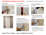
Door Installation -- Step 1
The doors are packed individually for protection of
the mirror surfaces. Carefully remove the door
from the carton.* Hold the door in the upright
position snap open the factory installed hinges.
Place the hinge onto the factory-installed
mounting toe/hinge plate in the cabinet --
Toe rst -- and snap into position. Be careful not
to chip the door mirror.
Always test adjustment by holding your
ngers behind the door to be sure the mirror
is not hitting the top and bottom cover plates.
*Do not remove corner protectors until the door is
installed
WARNING
Read this installation page PRIOR to
installing the cabinet’s MIRRORED DOOR
to avoid potential damage or breakage
of glass.
When installing the cabinet door with VTL Lights fixed,
becareful not to chip the door mirror. It is important to test
the distance between the door’s glass edge and the
light’s top and bottom cover plates PRIOR to fully closing
the door. The factory installed hinge may need to be ad-
justed left or right for proper clearance.
Damage to glass door during installation is not the
responsibility of GlassCrafters Inc. and may result in
loss of product warranty.

13
1) Insert into
Hinge Toe
first
Hinge Plate
2) Lift and snap
into place
Outside Mirror
Door Frame
Cabinet
Face
Inside Mirror
Maximum
adjustment
Left to right
1 MM
LED Light
Top & Bottom
Cover Plates
Detail 2
Hinge Plate
Hinge Plate
LED Light
Top & Bottom
Cover Plates
Detail 1
(CAUTION) Check adjustment
carefully to avoid door hitting Top
and Bottom Light Cover Plates
Top view
Step 1- Snap Hinge into place
Step 2-- Test Door Clearance
Door Installation continued
CAUTION: Always test by closing the door
with your hand behing the door to test door
clearance and determine if any adjustment
is needed to avoid door hitting Top and
Bottom Light Cover Plates.
If adjustment is needed follow
instructions in Step 3 (page 14).
To view a video showing helpful tips on how to adjust
our cabinet hinges, please go to --
GlassCraftersMirrored Cabinets.com and navigate to the
cabinet product that you are installing. Simply click on
the installation tab (located below the product images)
to view our installation videos.

14
#3
Screws adjust
for Flush Fit
to cabinet face
#2
Screws adjust
for Fit to
Top and Bottom
to cabinet face
#1
Screws adjust
for Fit alignment
left and right
to cabinet face
Other adjustments for the door--
Blum Hinge Adjustment
When the doors adjustments are completed
place cover caps on hinges.
Step 3 - Hinge Adjustment:
(CAUTION) Check door and adjustment carefully
using the screw adjustmets on the hinge as shown.
Left and right hinge adjustment is limited to 1/32”
(1 mm).
Test by closing the door with your hand behing the
door to test the clearance to avoid door hitting Top
and Bottom Light Cover Plates.
Open door and adjust using #1 screw as shown in
the diagram below and retest clearance.
#1 Screw -
Adjust Door Left to Right
(Maximu adjustment 1mm)
Test fit before closing completely
#3 Screw -
Adjust Door
Front to Back
#2 Screw -
Adjust
Top to Bottom
Hinge Plate
Hinge Plate* Factory Installed.
*If the door binds and does not fully
close, adjust the Hinge Plate on the
cabinet up and down, to relieve the ten-
sion.

15
Limit Clips
Limit Clips are provided should you need to re-
duce the opening swing of the cabinet door from
170 degrees to 130 degrees (see top view) This
will eliminate the possibility of the door hitting a
wall sconce or other decorative items.
Special adjustments of these clips is required with
the Vertical Light Mirrored Cabinet. Use caution
when testing the opening swing of the door.
Rececess Cabinet Door Swing Diagrams
Finished surface
Finished surface
Cabinet
Cabinet
170º swing
130º swing

16
VERTICAL LED TASK LIGHTS WARRANTY
GlassCrafters, Inc. offers a limited 1 year warranty on all Vertical LED Task Lights
products. GlassCrafters’ warranty provides the original purchaser a guarantee that
it will replace or at its own discretion repair products shown to have substantial
defects in workmanship or materials. These claims must be filed with your dealer
or professional installer and forwarded in writing to GlassCrafters within one year
of the delivery date to the end user of the product. GlassCrafters shall not be
responsible for any installation or removal costs. This warranty does not apply to
the following, chemical or natural corrosion of the acrylic diffuser. The use of
abrasive cleaners or cleaners containing ammonia will cause chemical damage to
the acrylic diffuser, voiding this warranty.
The GlassCrafters warranty does not cover product that is damaged in shipping,
accidents in handling during installation or if the reported defects are a result of
faulty installation, abuse, misuse, abnormal wear, poor maintenance, accident or
repairs by service personnel other than the original professional installer as
authorized by GlassCrafters. After the one year period GlassCrafters shall not
have any further obligation, expressed or implied including merchantability
under the Limited Warranty.
GlassCrafters shall not have any liability for any consequential damages
stemming from or in connection with the use per performance of this product.
Prevailing state law on the limits of the implied warranty will apply.
The liability of GlassCrafters under any implied or expressed warranty, including
merchantability, is expressly limited to the terms of this warranty. Any claim
under this warranty must be made directly to the dealer of record.
Permission to return any merchandise under this warranty must be authorized
in writing by GlassCrafters and must include prepaid shipping by the purchaser
.
Revised 06/2016
GLASSCRAFTERS, INC
193 Veterans Blvd., Carlstadt, NJ 07072
1+(800) 233-7362 (F) 1+(888) 233-7362
/