
Indoor Carbon Monoxide Monitor
EC-600
Operating Manual
Part Number: 71-0417
Revision: P1
Released: 3/22/17

2
Contents
1. Outline of the Product ..................................................................................................................................... 3
Preface ............................................................................................................................................................ 3
Purpose of use ................................................................................................................................................ 3
Definition of DANGER, WARNING, CAUTION and NOTE ............................................................................ 4
Method of confirmation for CE marking type .................................................................................................. 4
2. Important Notices on Safety ........................................................................................................................... 5
2-1. Danger cases........................................................................................................................................... 5
2-2. Warning cases ......................................................................................................................................... 6
2-3. Precautions .............................................................................................................................................. 6
3. Product Components ...................................................................................................................................... 7
3-1. Main unit and standard accessories ........................................................................................................ 7
3-2. Names and functions for each part ......................................................................................................... 9
4. How to Install ................................................................................................................................................ 12
4-1. Precautions for installation points ......................................................................................................... 12
4-2. Precautions for system designing ......................................................................................................... 13
4-3. Installation of main unit .......................................................................................................................... 15
4-4. Precautions for wiring ............................................................................................................................ 18
5. How to Use ................................................................................................................................................... 21
5-1. Before using the monitor ....................................................................................................................... 21
5-2. Preparation for start-up ......................................................................................................................... 21
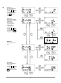
5-3. Basic operating procedures ................................................................................................................... 22
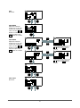
5-4. Power-on ............................................................................................................................................... 23
5-5. Modes .................................................................................................................................................... 24
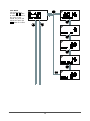
5-6. User mode ............................................................................................................................................. 25
5-7. Power-off ............................................................................................................................................... 28
6. Alarm Activation and Functions .................................................................................................................... 29
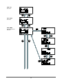
6-1. Gas alarm activation .............................................................................................................................. 29
6-2. Fault alarm activation ............................................................................................................................ 34
6-3. Suppression function ............................................................................................................................. 34
7. Maintenance ................................................................................................................................................. 35
7-1. Maintenance intervals and items ........................................................................................................... 35
7-2. Maintenance (regular maintenance) mode ........................................................................................... 36
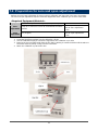
7-3. Preparation for zero and span adjustment………………………………..…………………………………42
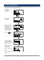
7-4. Zero Adjustment………………………………………………………………………………………………..43
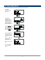
7-5. Span Adjustment……………………………………………………………………………………………….44
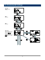
7-6. Environmental Settings………………………………………………………………………………………..45
7-7. Return to User Mode…………………………………………………………………………………………..52
7-8. Component Replacement……………………………………………………………………………………..52
7-9. Replacing a Sensor Cable…………………………………………………………………………………….54
7-10. Adding a Sensor Cable……………………………………………………………………………………….57
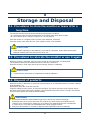
8. Storage and Disposal ................................................................................................................................... 62
8-1. Procedures to store the monitor or leave it for a long time ................................................................... 62
8-2. Procedures to relocate the monitor or use it again ............................................................................... 62
8-3. Disposal of products .............................................................................................................................. 62
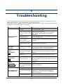
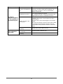
9. Troubleshooting ............................................................................................................................................ 63
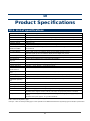
10. Product Specifications ................................................................................................................................ 65
10-1. List of specifications ............................................................................................................................ 65
10-2. List of accessories ............................................................................................................................... 66
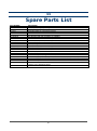
11. Parts List…………………………………………………………………………………………………………….67
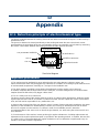
12. Appendix ..................................................................................................................................................... 68
12-1. Detection principle of electrochemical type ......................................................................................... 68
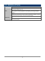
12-2. Definition of terms ................................................................................................................................ 69

3
1
1. Outline of the Product
Preface
Thank you for choosing our indoor carbon monoxide monitor EC-600 (hereinafter referred to as the
monitor). Please check that the model number of the product you purchased is included in the
specifications on this manual.
This manual describes how to use the monitor properly and its specifications. First-time users and users
who have already used the monitor must read and understand the operating manual and use this product
as described in this manual.
Note that the contents of this manual are subject to change without notice for product improvement. It is
also prohibited to copy or reproduce this manual, in whole or in part, without permission.
Regardless of warranty period, we shall not make any indemnification for accidents and damage caused by
using the monitor.
Make sure to read the warranty policy specified on the warranty.
Purpose of use
This carbon monoxide monitor measures carbon monoxide in the air and issues an alarm using the buzzer
and LCD backlight when carbon monoxide concentration rises over a preset concentration (alarm setpoint).
While displaying measured carbon monoxide concentration on the LCD, the monitor converts it to an
analog signal of 4 - 20 mA or 0 - 1 V to output (only 0 - 1 V for the dry battery type) and outputs a two-step
gas alarm contact at a gas alarm state.
The monitor is a safety unit, not an analyzer which performs quantitative/qualitative analysis/measurement
for gas. Check the specifications before use and conduct measurement properly in accordance with
purposes.

4
Definition of DANGER, WARNING, CAUTION and NOTE
Throughout this manual, the following indications are used to ensure safe and effective work.
DANGER
This message indicates that improper handling may cause serious
damage on life, health or assets.
WARNING
This message indicates that improper handling may cause serious
damage on health or assets.
CAUTION
This message indicates that improper handling may cause minor damage
on health or assets.
NOTE
This message indicates advice on handling.
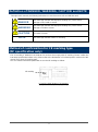
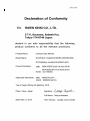
Method of confirmation for CE marking type
(DC specification only)
The CE marking is labeled on the detector for versions that comply with CE marking. Please confirm the
instrument specification before using. Please refer to the Declaration of Conformity that is at the end of this
manual if you have CE marking type.
You can confirm instrument specification to see the CE marking as follows.
CE marking label (Bottom of instrument)
(DC specification, dry battery type only)
CE marking

5
2
2. Important Notices on
Safety
To maintain the performance of the monitor and use it safely, observe the following instructions with
WARNING and CAUTION.
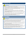
2-1. Danger cases
DANGER
• This is not an explosion-proof unit. Never attempt to measure a gas in an atmosphere over the
lower explosive limit.
WARNING
• If an abnormality is found in the monitor, contact RKI immediately. Visit our Web site to find your
nearest RKI office.
Web site: www.rkiinstruments.com

6
2-2. Warning cases
2-3. Precautions
WARNING
• Before turning on the monitor, always check that the voltage is compliant with the specifications.
Operating on an unstable power supply may cause malfunctions.
• When the gas adjustment is performed, never fail to perform the air (zero) calibration in fresh air.
• Do not operate this monitor in a place where combustible/explosive gases or vapors are present.
Operating the monitor in such an environment will lead to extreme dangers.
• Issuance of a gas alarm indicates that there are extreme dangers. Take proper actions based on
your judgment.
• Perform span adjustment at fixed intervals.
• Do not run the power cable and remote sensor cable of the monitor in parallel with cables of
high-frequency or high-voltage and other device's power cables. It may cause malfunctions.
• If a cable of high-frequency or high-voltage and the power cable need to intersect with each other,
it should be orthogonally connected.
• When wiring, be careful not to apply any stresses on the cables by pulling, tightening or twisting,
etc.
• Do not disassemble/modify the monitor. It may invalidate the warranty of the performance.
Changing the settings without understanding them may cause alarm malfunctions. Please use the
monitor properly in accordance with the operating manual.
• Do not use the monitor with it attached to a control device, equipment, etc.
CAUTION
• Do not use a device, such as a transceiver, which transmits a radio wave near the monitor or its
cables. It may affect the measurement. If a transceiver or other radio wave transmitting device is
used, it must be used in a place away from the monitor where it disturbs nothing.
• Restarting the monitor within five seconds after turning it off may cause errors.
• This is not a control unit. It is not allowed to use the external output of the monitor to control other
units.
• This is a safety unit. Never fail to perform a regular maintenance to ensure safety. Continuing to use
the monitor without performing maintenance will compromise the sensitivity of the sensor, thus
resulting in inaccurate gas detection.
• Do not pick the sensor or buzzer opening with a sharp-pointed item. The unit may cause
malfunction or get damaged, possibly resulting in incorrect measurements.
• Do not let the monitor draw in water. Do not install the monitor in a place where the monitor may get
wet. Ignoring this may cause malfunction because the monitor is not water- or drip-proof.
• This is a precision device. Do not give strong shock or vibration to the monitor.
• When the case is opened for wiring or other operation, do not touch inner parts. When wiring, be
sure that excessive pressure is not applied to the power cable and remote sensor cable.
• Do not block the vent for the sensor.

7
3
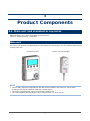
3. Product Components
3-1. Main unit and standard accessories
After opening the box, check the monitor and accessories.
If there is anything missing, contact RKI.
Main unit
For names and functions of individual parts of the monitor and LCD display, see "3-2. Names and functions
for each part" (P.9).
EC-600 main unit
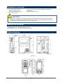
Sensor unit (remote type)
NOTE
• The EC-600’s standard configuration is with the sensor installed in the main unit. Specify when
ordering if you want an extender cable with a remote sensor.
• The sensor integrated type does not include the remote sensor.
• The cable length for the remote type can be selected from 3, 5, 10 and 20 m.

8
Standard accessories
- Cross-recessed pan head
machine screw (2 pcs.)
- Cross-recessed round head
wood screw (2 pcs.)
- 3.2 m AC power cable (1 pc.) *Supplied only with AC
specification
- Operating manual (1 pc.)
Optional accessories
- Mounting plate (1 pc.) RKI part number: 21-1927
- Gas calibration cup (1 pc.) RKI part number: 81-1153
Outline drawing
Main unit
Remote sensor
(Unit: mm)
CAUTION
• The main unit and sensor unit (remote type) are precision devices. Be careful not to drop the
monitor when installing or uninstalling the main unit or sensor unit. Dropping the monitor may
compromise its original performance or cause malfunctions.
Power switch
Cable outlet
Cable outlet
Cable outlet
Cable outlet
Display
Sensor
part
Mounting hole for 3-M3
Use one of the two for
lower holes
To main unit
Sensor
part

9
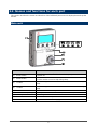
3-2. Names and functions for each part
This section describes the names and functions of the individual parts and LCD display that make up the
monitor.
Main unit
Name
Major function
(1) Power switch
Turns the power ON/OFF. Slide the switch up to power on and down
to power off.
(2) MODE button
Hold down this button to enter the user mode.
It is also used to cancel or skip during setup.
(3) ˄ button
Used to change the screen and increase numerical values during
setup.
(4)
˅
button
Used to change the screen and decrease numerical values during
setup.
(5)
SET button
Used to confirm the setting.
(6)
Buzzer sound opening
Emits operation and alarm sounds. (Do not block it.)
(7)
Sensor part
Detects a gas to be detected. The sensor is inside the cover.
(8)
Screw
Loosen this screw to open the case.
(9)
Activated carbon filter
Remove influence of the sloppy gas.
9

10
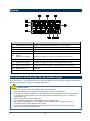
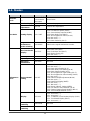
Display
Name
Major function
(1)
Operating state display
Displays the operating status. Blinks at a normal state.
(2)
1st alarm display
Lights up or flashes orange at a first alarm state.
(3)
2nd alarm display
Lights up or flashes red at a second alarm state.
(4)
Fault alarm display
Lights up in red at a fault alarm state.
(5)
Concentration value
display
Maintenance indicator
Displays the gas concentration.
Maintenance items and others are displayed during setup.
(6)
Unit display
Displays the unit (ppm) according to the specification.
(7)
Gas name display
Maintenance display
Displays the gas name.
Maintenance items and others are displayed during setup.
(8)
AC/DC power display
Lights up when the monitor is operating on AC or DC power.
(9) Battery level icon
Displays the battery level when the monitor is operating on dry
batteries.
(10)
This is not used for the monitor.
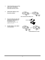
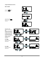
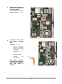
Installation of batteries (for dry battery type)
When the monitor is used for the first time, or when the battery level is low, install or replace with new AA
alkaline dry batteries according to the following procedure.
CAUTION
• Turn off the power of the monitor before replacing the batteries.
• Replace the batteries in a safe place where explosive gases are not present.
• Never fail to use alkaline batteries. If a rechargeable (secondary battery) nickel-cadmium battery
or nickel metal hydride battery is used, the specifications cannot be met, such as continuous
operating time, etc.
• Replace both batteries at the same time.
• Pay attention to the polarities of the batteries when installing them.
• After installing the batteries, lock the battery cover completely. If the battery cover is not
completely locked, the dry batteries may fall out.
• Do not use rechargeable batteries that may interrupt a measurement due to the discharge
characteristic of rechargeable batteries.

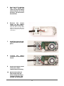
11
1
Check that the power of the
main unit is turned off.
If the power is turned on, slide the
power switch down to turn it off.
2
Remove the battery case
from the monitor.
Unlock the tab of the battery case.
3 Put new batteries (two AA
alkaline dry batteries) in
the battery case.
Confirm that the polarities of the
batteries are correct.
4
Put the battery case back
in the monitor.
Push the circled area and
confirm that the tab is locked.
New battery

12
4
4. How to Install
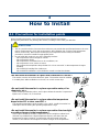
4-1. Precautions for installation points
When installing the monitor, never fail to observe the following precautions.
Ignoring the precautions may damage the monitor, resulting in inaccurate gas detection.
<Do not install the monitor in a place with vibrations or shocks.>
The monitor consists of sensitive electronic parts. The monitor must be installed
in a stable place without vibrations or shocks, etc. and it cannot drop.
<Do not install the monitor in a place exposed to water, oil or
chemicals, etc.>
When selecting installation points, avoid a place where the monitor is exposed to
liquids such as water, oil, or chemicals.
<Do not install the monitor in a place where the temperature
drops below 0ºC or rises over 40ºC.>
The operating temperature of the monitor is 0 to +40ºC. Install the monitor in a
stable place not exceeding the operating temperature range.
<Do not install the monitor in a place exposed to direct sunlight
or sudden changes in the temperature.>
Avoid a place where the monitor is exposed to direct sunlight or radiant heat
(infrared rays emitted from a high-temperature object), and where the unit
temperature changes suddenly. Condensation may be formed inside the
monitor, or the monitor cannot adjust to sudden changes in the temperature.
CAUTION
• This is a precision device. Because the monitor may not provide the specified performance in some
places (environments), check the environment in the installation site, and then take appropriate
actions if necessary. Because the monitor plays an important role for safety and disaster
prevention, it must be installed in appropriate points.
• Do not install this product in any of the following locations.
- Place exposed to direct sunlight or outside
- Place exposed to water
- Place exposed to ventilation from an air conditioner, etc.
- Place exposed to soot, smoke or steam
- Place where the temperature drops below 0ºC or rises over 40ºC or the temperature changes
suddenly
- Place with high humidity like a bathroom
- Place with bad ventilation such as behind a curtain or under the shadow.

13
<Keep the monitor (and its cables) away from noise source
devices.>
When selecting installation points, avoid a place where
high-frequency/high-voltage devices exist.
<Do not install the monitor in a place where maintenance of the monitor cannot
be performed or where handling the monitor involves dangers.>
Regular maintenance of the monitor must be performed.
Do not install the monitor in a place where the machinery must be stopped when maintenance is
performed in its inside, where parts of the machinery must be removed to perform maintenance, or
where the monitor cannot be removed because racks or other things prevent access to it. Do not
install the monitor in a place where maintenance involves dangers, for example, near a high-voltage
cable.
4-2. Precautions for system designing
Note the following precautions for system designing of the monitor.
Using a stable power supply
The external output and alarm contact of the monitor may be activated when the power is turned on, when
momentary blackout occurs, or when the system is being stabilized. In such cases, use a UPS
(uninterruptible power system), or take appropriate actions on the receiving side.
The monitor must be provided with the following power supply.
Power supply
voltage
100 VAC ±10% (50/60 Hz), 24 VDC±10% or AA alkaline dry battery (2 pcs.)
Allowed time of
momentary
blackout
Up to 10 milliseconds
(To recover from the momentary blackout for 10 milliseconds or more, restart the
monitor.)
Example of actions
To ensure continuous operation and activation, install a UPS (uninterruptible
power system), etc. outside the monitor.
Others
Do not use it with a power supply of large power load or high-frequency noise.
Example of actions
Use a line filter, etc. to avoid the noise source if necessary.
CAUTION
• An unstable power supply and noise may cause malfunctions or false alarms.

14
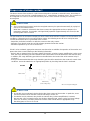
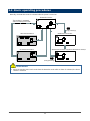
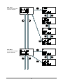
Proper use of alarm contact
The alarm contact of the monitor is used to transmit signals to activate an external buzzer, alarm lamp or
rotating lamp. Do not use it for controlling purpose (e.g., controlling the shutdown valve). The contacts can
be configured as Form A or Form B but are factory set as Form A contacts and they are normally
de-energized.
The specifications for the external output gas alarm contact of the monitor are based on the resistance load
conditions. If inductive load is used at the alarm contact, the following errors will occur easily because
counter electromotive force is generated at the contact.
- Deposition, defective insulation or defective contact at the relay contact
- Damage of any electric parts due to high-voltage generated inside the monitor
- Abnormal operations by an out-of-control CPU
If load is to be activated, appropriate measures must be taken to stabilize the operation of the monitor and
protect the alarm contact referring to the following information.
- Relay it with an external relay at a lower voltage of 100 VAC or below (contact amplification). At the same
time, the surge absorbing part SK1 suitable for the specifications must be attached to the external relay.
- In addition, the surge absorbing part SK2 must be attached to the loaded side of the external relay if
necessary.
- It may be recommended that the surge absorbing part should be attached to the contact for certain load
conditions. It must be attached to an appropriate position by checking how the load is activated.
CAUTION
• The b contact (break contact) under de-energized state may be opened momentarily by a physical
shock, such as external force.
When the b contact is selected for the alarm contact, take appropriate actions to prepare for a
momentary activation, for example, add signal delay operation (approximately one second) to the
receiving side of the b contact.
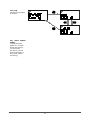
EC-600
CAUTION
• In principle, do not activate inductive load at the alarm contact of the monitor. In particular, never
use the inductive load to activate a fluorescent lamp or motor, etc.
• If inductive load is activated, relay it with an external relay (contact amplification). However,
because the coil of an external relay also involves inductive load, select a relay at a lower voltage
(100 VAC or below), and then protect the contact of the monitor with an appropriate surge
absorbing part, such as a CR circuit.
Alarm contact
Power
supply
Power
supply
Coil
External relay
(Lower voltage relay)
Load
*SK1, SK2: Surge absorbing part

15
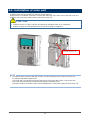
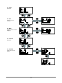
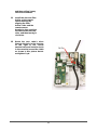
4-3. Installation of main unit
Install the main unit on the wall 50 to 180 cm up from the floor.
If wall screws are available, remove the screw at the lower part of the main unit to open the cover and
install the unit using the mounting holes on the back of the unit.
NOTE
• To install the main unit to the wall with screws, use the mounting holes on the back of the unit
according to the following procedure.
(1) Loosen the screw at the lower part of the main unit and open the surface cover of the case.
(2) Fix the main unit with two screws (M4) through the mounting holes.
(3) Put the surface cover back on the case and tighten the screw at the lower part of the main unit.
CAUTION
• Install the sensor in a place not directly exposed to ventilation from an air conditioner.
• Sudden changes in the temperature may cause the readings to disappear.
Mounting hole (for M4 screw)
*Supporting the switch box

16
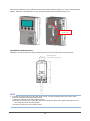
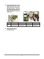
If the monitor operating on dry batteries needs to be removed with the power on, use the mounting plate
(option). When the mounting plate is used, install the plate before installing the main unit.
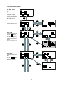
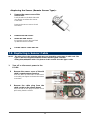
<Installation of Remote Sensor>
Tighten the screws through one upper mounting hole and one of the two lower mounting holes.
NOTE
• To install the remote sensor to the wall using screws, use the mounting holes on the back of the
sensor according to the following procedure.
(1) Open the surface cover of the remote sensor.
(2) Fix the sensor with two screws (M3) through the mounting holes (one upper mounting hole and
one of the two lower mounting holes).
(3) Put the cover back on the remote sensor.
Mounting hole for 3-M3
Use one of the two for lower holes
To main unit
Mounting hole
(for M4 screw)

17
<Maintenance Space>
To use dry batteries, secure a maintenance space for battery replacement below the unit. If the mounting
plate (option) is used, secure an installation space above the unit so that it can be installed by sliding.
Secure as battery replacement space
(Only for dry battery type)
Installation dimension drawing (Installation board not used)
Compatible with JIS single switch box
Secure as
installation space
Installation dimension drawing (Installation board used)
Secure as battery replacement space
(Only for dry battery type)

18
4-4. Precautions for wiring
If the monitor operates on AC or DC power or if an inductive load is used at the alarm contact, wiring work
is required.
The following cables are recommended for wiring the monitor with the power supply, signal cable and
contact.
<Recommended Cables>
For AC power
Solid wire/stranded wire: 0.2 - 1.5 mm
2
For DC power
CVVS: 0.2 - 1.5 mm
2
For signal cable (4 - 20 mA/0 - 1 V)
CVVS: 0.2 - 1.5 mm
2
For contact
Cable such as CVV (0.2 - 1.5 mm
2
) Up to 4 cores
<Cable Connection Conditions>
Connectable cable, bare wire length and connection tools are as follows:
- Cable: 0.2 - 1.5 mm
2
- Bare wire length: 10 - 11 mm
- Connecting tools: Dedicated screwdrivers manufactured by WAGO and equivalent (edge width 3.0 to 4.5
mm x 0.5 mm)
<Compatible Bar Terminal>
For a bar terminal, the following items are available. See the spare parts list for RKI part numbers.
- Bar terminal (ferrule): Model 216 Series (manufactured by WAGO)
- Crimping tool: Model VarioCrimp 4 (206-204) (manufactured by WAGO)
CAUTION
• Be careful not to damage the internal electronic circuit when wiring. In addition, be careful not to
apply stresses on the monitor when (overweight) cables are installed.
• The power and signal cables must be wired separately from the motor power cables.
• When stranded wires are used, prevent wires from contacting each other.
CAUTION
The specified bare wire length must be observed when the wire insulation is peeled off.
• Improper clamping of the wire due to a shorter bare wire length may cause defective electric
conduction or heating.
• Catching the wire insulation due to a shorter bare wire length may cause defective electric
conduction or heating.
• Exposing the wire due to a longer bare wire length may cause defective insulation or a short circuit.
• Be careful not to break up the wire. If the wire is broken up when inserted to the terminal, this may
cause defective insulation or heating.
CAUTION
• A bar terminal of the specified model must be used. Using other bar terminals invalidates the
warranty of the performance.

19
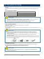
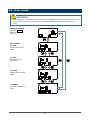
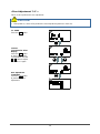
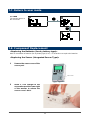
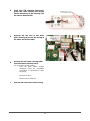
How to connect to terminal plate
When cables (wires) are connected to the terminal plate inside the main unit, use the dedicated
screwdriver or a compatible flathead screwdriver.
When connecting a stranded wire, be sure to press the push button and open the spring while connecting
the wire.
1
Push the push button
straight downward using
the compatible screwdriver
or equivalent to open the
spring.
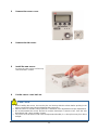
2
Insert a wire with a
specified bare wire length
(10 mm) until the end of it
reaches the deepest point.
3
Release the screwdriver.
The wire is connected.
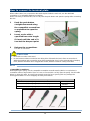
NOTE
<Compatible Screwdriver>
When opening the spring, use the compatible screwdriver manufactured by WAGO or equivalent (a
screwdriver with an edge width of 3.0 to 4.5 mm x 0.5 mm which can fully open the spring: See the table
below). In doing this work, be careful not to apply excessive force. Ignoring this may damage the
housing/push buttons or cause dropping off of the push buttons.
Compatible screwdriver manufactured by WAGO
Screwdriver (M) straight type
210-120J
Screwdriver (M) straight type (short shaft & grip)
210-350/01
210-657
Screwdriver (M) straight type (insulated shaft type)
210-720
CAUTION
• Never fail to use the correct tool.
• Do not insert more than one wire into one wiring hole. If the total size (mm
2
) of two or more wires is
within the maximum wire connection range of the terminal plate, it may cause reduced spring clamping
force, defective insulation due to clogged wire sheath, defective contact or coming off of wires.

20
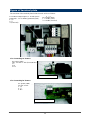
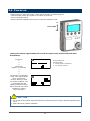
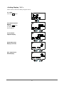
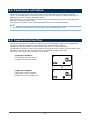
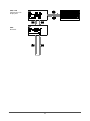
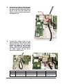
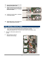
Figure of terminal plate
The overview of the terminal plate inside the main unit is as follows:
<For Connecting AC Power>
<For Connecting DC Power>
AC power (TND)
100 - 120 VAC ± 10% (50 Hz/60 Hz)
1: L
2: N
3: FG
Terminal board for AC power
Terminal board for DC power
DC power (TND)
24 VDC ± 10%
1: (+)
2: (-)
3: N.C
For external output signal (4 - 20 mA for line
powered/0 - 1 V for battery powered) (TN2)
1: (+)
2: (-)
3: (not used)
For contact (TN3)
1 - 2: ALM1 (First)
3 - 4: ALM2 (Second)
Page is loading ...
Page is loading ...
Page is loading ...
Page is loading ...
Page is loading ...
Page is loading ...
Page is loading ...
Page is loading ...
Page is loading ...
Page is loading ...
Page is loading ...
Page is loading ...
Page is loading ...
Page is loading ...
Page is loading ...
Page is loading ...
Page is loading ...
Page is loading ...
Page is loading ...
Page is loading ...
Page is loading ...
Page is loading ...
Page is loading ...
Page is loading ...
Page is loading ...
Page is loading ...
Page is loading ...
Page is loading ...
Page is loading ...
Page is loading ...
Page is loading ...
Page is loading ...
Page is loading ...
Page is loading ...
Page is loading ...
Page is loading ...
Page is loading ...
Page is loading ...
Page is loading ...
Page is loading ...
Page is loading ...
Page is loading ...
Page is loading ...
Page is loading ...
Page is loading ...
Page is loading ...
Page is loading ...
Page is loading ...
Page is loading ...
Page is loading ...
-
 1
1
-
 2
2
-
 3
3
-
 4
4
-
 5
5
-
 6
6
-
 7
7
-
 8
8
-
 9
9
-
 10
10
-
 11
11
-
 12
12
-
 13
13
-
 14
14
-
 15
15
-
 16
16
-
 17
17
-
 18
18
-
 19
19
-
 20
20
-
 21
21
-
 22
22
-
 23
23
-
 24
24
-
 25
25
-
 26
26
-
 27
27
-
 28
28
-
 29
29
-
 30
30
-
 31
31
-
 32
32
-
 33
33
-
 34
34
-
 35
35
-
 36
36
-
 37
37
-
 38
38
-
 39
39
-
 40
40
-
 41
41
-
 42
42
-
 43
43
-
 44
44
-
 45
45
-
 46
46
-
 47
47
-
 48
48
-
 49
49
-
 50
50
-
 51
51
-
 52
52
-
 53
53
-
 54
54
-
 55
55
-
 56
56
-
 57
57
-
 58
58
-
 59
59
-
 60
60
-
 61
61
-
 62
62
-
 63
63
-
 64
64
-
 65
65
-
 66
66
-
 67
67
-
 68
68
-
 69
69
-
 70
70


Ask a question and I''ll find the answer in the document
Finding information in a document is now easier with AI
Related papers
-
RKI Instruments OX-600 Owner's manual
-
-
-
-
-
-
-
-
-
Other documents
-
Zip 100531186 User guide
-
 Riken Keiki OX-600 Operating instructions
-
Citizen AP1053-23W Disney Classic Setting Instruction
-
Myfox TA4010 User manual
-
American Power Conversion MX28B4800 User manual
-
 New Cosmos Electric KS-7D User manual
-
MSA Toxgard® II Gas Monitor Owner's manual
-
 Riken Keiki RM-5000-06W Operating instructions
-
 LS META MEC Series User manual
-
 Riken Keiki NP-5001 Operating instructions


