Page is loading ...

Gate Controller ATC 100
Installation and
Operating Manual
Antriebs- und Steuerungstechnik
Am Grarock 8 • D-33154 Salzkotten
Tel.: 0 52 58/93 27-0 • Fax: 0 52 58/34 48
www.asogmbh.de • e-mail: [email protected]

Gate Controller ATC 100
2
1. Important safety warnings
2. General
2.1 Highest safety for humans and objects
2.1 The advantages of the ATC 100
3. System components
3.1 LED - indicators
4. Electrical connection
4.1 Mains voltage
4.1.1 Connection three-phase motor
4.1.2 Connection single-phase motor
4.2 Relay outputs (potential free)
4.3 STOP inputs
4.4 Inputs for control switches
4.5 Light-barrier inputs
4.6 Safety-contact-edge connection
4.7 Limit switches inputs
4.8 Power supply 24V
5. Plug-on modules
5.1 Control modules
5.2 Auxiliary modules
5.2.1 Inductive safety controller ISK 70-75
5.2.2 Time switch ZU3
5.2.3 Radio controller
6. Program settings
6.1 Automatic
6.2 Manual mode
6.3 Input
6.4 Diagnosis
7. Jumper settings
8. Article numbers
9. Enclosure
9.1 Mounting of the enclosure
9.2 Enclosure dimensions
10.Technical data
..................................................................................................... 3
.................................................................................................................................. 4
............................................................................................................. 4
............................................................................................................................. 4
............................................................................................................... 5
....................................................................................................................................................... 6
............................................................................................................. 7
............................................................................................................................................................ 8
................................................................................................................................. 8
............................................................................................................................... 9
............................................................................................................................. 10
........................................................................................................................................................... 11
................................................................................................................................... 11
................................................................................................................................................ 11
......................................................................................................................... 12
............................................................................................................................................ 12
.................................................................................................................................................. 12
.................................................................................................................. 13
....................................................................................................................................................... 13
..................................................................................................................................................... 13
...................................................................................................................... 13
.....................................................................................................................................................13
..................................................................................................................................................... 13
.................................................................................................................. 14
................................................................................................................................................................. 14
......................................................................................................................................................... 14
...................................................................................................................................................................... 14
.............................................................................................................................................................. 16
.................................................................................................................... 17
.................................................................................................................... 17
.............................................................................................................................17
.................................................................................................................................... 17
........................................................................................................................................ 17
..................................................................................................................... 18
Contents

3
1. Important safety notes
• This manual must be available at the installation place of the gate controller at all time.
Any person assigned with the installation, operation and maintenance of the gate controller must read and follow this manual.
• Basic condition for safety-related handling and the failure-free operation of the gate controller is the knowledge of the fundamental
safety guidelines and the safety regulations of the European standards and the professional associations.
• This manual, in particular the safety guidelines, are to be considered from all persons who works on the gate controller
• For safety reasons the electrical installation is only to accomplished from a qualified electrical personnel according to the locally
valid regulations for the prevention of accidents.
• The opening of the gate-controller is only permitted with switched off power supply. For the disconnection of the power supply a
main power switch or the use of a CEE plug is to be planned. The main power switch or the power supply plug must be easily
accessible.
• Before performing any work on the gate controller, the voltage must be disconnected and verified that there is no live voltage.
• If the potential free contacts of the relay outputs are connected to a dangerous voltage, it is also necessary to switch off these voltages
before working on the gate controller.
• The operation of the control with an opened enclosure is not permitted.
• Switching on and/or operation of a dewed gate controller is not permitted and can destroy the controller.
• The used stage nipple cable insertion may only cut to the stage, so that the insertion of the cable corresponds to the IP 54
protection against water and foreign objects.
Damaged stage nipples must be exchanged immediately against intact.
• The intended use of the safety controller is the use at gates and doors. A different, or beyond this, use is not intended. The
manufacturers do not assume liability for damages and malfunctions caused by not intended use.
The manufacturer must permit the use in special applications.
• Faults, which can affects the safety, must be eliminated immediately.
• With the use of the gate in the manual mode operation it is to be guaranteed that the gate range can be seen by the operator.
• At the start-up operation and at the annually prescribed maintenance the parameter settings and the correct function of the safety
device must be examined.
The settings of the parameters and the maintenance of the gate situation may only checked by a qualified personnel. The results must
be documented in such a way that it can be viewed and understood at any time.
• Never allow that children operate the gate controller. Take care that children don't play in the near or with the gate. Keep radio remote
controllers in a place which is inaccessible to children.
• The manufacturer and the user of the gate, at which the controller is used, are responsible for the compliance with all valid safety
regulations.
• The gate controller guarantees for itself a functional safety, however not the complete safety of the gate. Therefore, a safety
consideration for the complete gate, according to the machinery directive 98/37 EC or to the appropriate product standard, is necessary
before using this gate controller.
• The gate controller contains no user-serviceable parts. Any unauthorised modifications and/or repairs of the gate controller will
terminate any guarantee and claim against the manufacturer.
The ATC 100 gate controller must be regarded as a component.
It lies in the responsibility of the gate manufacturer and/or gate operator to ensure that its gate
meets all relevant regulations and standards (machinery directive, EMC guideline etc.).
Technical and operating relevant changes to the products and devices specified in this documentation
are reserved at any time also without advance notice.

Gate Controller ATC 100
4
2.2 The advantages of the ATC 100
• compact enclosure
• connecting possibility for three-phase and one-phase motors
through the integrated reversing contactors
• simple, menu-driven programming of the controller by four
buttons
• if necessary the pluggable control module offers protection
against unauthorized access of the adjusted parameters
• malfunction and operating conditions are indicated by the
two-line LCD display and by Led's
• integrated two-channal evaluation for stationary safety
contact edges
• socket for inductive safety system ISK to monitoring the
travelling safety contact edges at the gate wing
• socket for timer
• socket for radio controller
• alternatively complete or partial automatic revision after
operating the safety contact edges
• pluggable connecting terminals for simpler assembly
• ALL-IN-ONE solution for the gate-automation
2. General
The free parametrizable gate controller ATC 100 is developed for controlling 400V three-phase current and 230V one-
phase current motors on sliding gates, roller doors, roller grills, and sectional doors in industrial, commercial and
private use. As a result of the large flexibility, the variety of connection possibilities and the combination with further
optional plug-on modules the gate controller ATC 100 can be used in many areas.
By the menu-driven programming of the ATC 100 it is succeeded to simply arrange a complex control that fulfils
many requirements and functions.
2.1 Highest safety for humans and object
• Complete testing of all safety-related parts before each gate movement
• Testing the contactor contacts on correct function before each movement
• In case of an error a second shut-down circuit for the motor current is available by the additional release contactor.
As a compact unit the ATC 100 fulfils the requirements of the latest gate standards.

5
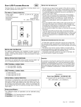
3. System components
Fuse 2AT/250V
Terminal clamps light and brake
Reversing contactor
Release contactor
Control module
Menu selection button
Function button
Terminal clamps supply voltage, motor
Terminal clamps inputs
Optional modules
Open (+) button
Close (-) button
Jumper J1
1
2
3
4
5
6
7
8
9
10
11
12
Jumper J2
13
Socket for ATC 100 control module
Led indicator safety contact edges
Socket for radio controller
Socket for timer
Socket for timer "looped"
Socket for inductive safety system ISK 70-75
Led indicator for selftest
Led indicators contactors
14
15
16
17
18
19
20
21
Week timer
radio controller
Inductive safety system ISK 70-75
22
23
24
UVW
M
F
1
2
A
T
I
S
K
LS
STOP
Open
Closed
Impuls
Closing
Direction
ISK
Coil Core
Limi t Switch
CL
T
i
m
e
S
w
i
t
c
h
L2 L3 N
1
2
3
4
5
6
7
8
9
J
1
J
2
A
T
C
1
0
0
Supply Voltage
3 x 400 V 50 Hz
M
E
N
U
O
K
+
2
4
1
5
1
4
1
3
1
2
1
1
7
6
5
8
9
1
0
2
0
1
9
1
8
1
7
1
6
Com
Com
STOP
A1
L
i
g
h
t
B
r
a
k
e
5
3
4
1
2
18
19
22
23
7
12
8 9 10 11
15
14
16
6
17
21
13
24
20

Gate Controller ATC 100
6
3.1 LED - indicators
Led indicator for the safety contact edges
Led indicators for the self-test
Led indicators for the contactors
6
7
8
9
J
2
1
0
1
2
3
4
5
LED 1 Release contactor switched
LED 2 Contactor for OPENING direction switched
LED 3 Contactor for CLOSING direction switched
LED 4 lights, if the safety contact edge(s) for the
OPENING direction is (are) OK
LED 5 lights, if the safety contact edge(s) for the
CLOSING direction is (are) OK
LED 6 Self-test failing
LED 7 Performing self-test step1 OPENING direction
LED 8 Performing self-test step2 OPENING direction
LED 9 Performing self-test step1 CLOSING direction
LED 10 Performing self-test step2 CLOSING direction

7
4. Electrical connection / Functional description
For safety reasons the electrical installation is only to accomplished from a qualified electrical
personal.
The opening of the gate-controller is only permitted with switched off power supply. For the
disconnection of the power supply a main power switch or the use of a CEE plug is to be
planned. The main power switch or the power supply plug must be easily accessible.
The points specified under the section
- Important Safety Notes -
are to be considered.
The close installation of signal- and electric power-lines should be avoided as far as possible.
All lines are to be dimensioned according to the capacity.
For a simply attaching of the individual wires the clamps 5 to 24 are pluggable.
The used stage nipple cable insertion may only cut to the stage, so that the insertion of the cable corresponds
to the IP 54 protection against water and foreign objects.
Damaged stage nipples must be exchanged immediately against intact.
Overview connectors
UVW
M
F1 2AT
ISK
L1 L2 L3 N
1
2
3
45
ATC 100
Supply Voltage
3 x 400 V 50 Hz
A2A1
Light
A4A3
Brake
Radio
Control
1312111095 678 2221201918171615
8,2k
Ω
8,2k
Ω
14
LS
STOP
Open
Closed
Impuls
Closing
Direction
OUT
+24V
GND
SKL
SKL
ISK
Coil Core
Opening
Direction
Closing
Direction
+24V
GND
Limit Switch
OP
CL
56789101112131415 16171819202122
2423
23 24
STOP
Com
Com
Supply Voltage connectors
Motor connectors
Light connectors
Brake connectors
Control switches connectors
Light barrier connectors
Safety device connectors
Limit switches connectors

Gate Controller ATC 100
8
4.1.1 Three-phase motor connection
For the connection of a three-phase motor the supply voltage
is to be connected to the clamps L1, L2, L3. For the internal
supply voltage of the ATC 100 it is necessary to connect the
neutral conductor to the clamp N. The electrical safeguarding
of the supply voltage is to be planned external and may have
an amount of max. 3 x 10A.
With the initial start-up of the gate pay attention to the rotation
direction of the motor (if necessary exchange the connections
V and W).
L1
L2
L3
N
Supply Voltage
3 x 400 V 50 Hz
M
PE-Clamps
U
V
W
Wiring regulation
In order to keep the safety class, the jackets of this cables, as represented in the drawings, must reach
up to the corresponding connectors.
The removing of the jackets to the cable-glands is not
permissible.
After wiring the cable-glands must be tightened firmly.
M
F1 2AT
ISK
1
2
3
45
ATC 100
Supply Voltage
3 x 400 V 50 Hz
A2A1
Light
A4A3
Brake
Radio
Control
1312111095 678 2221201918171615
8,2k
Ω
8,2k
Ω
14
LS
STOP
Open
Closed
Impuls
Closing
Direction
OUT
+24V
GND
SKL
SKL
ISK
Coil Core
Opening
Direction
Closing
Direction
+24V
GND
Limit Switch
OP
CL
5 6 7 8 9 10 11 12 13 14 15 16 17 18 19 20 21 22
2423
23 24
STOP
Com
Com
L1 L2 L3 N UVW
Supply Voltage
3 x 400 V 50 Hz
F1 2AT
ISK
L1 L2 L3 N
1
2
3
45
ATC 100
Supply Voltage
3 x 400 V 50 Hz
Light
Radio
Control
1312111095 678 2221201918171615
8,2k
Ω
8,2k
Ω
14
LS
STOP
Open
Closed
Impuls
Closing
Direction
OUT
+24V
GND
SKL
SKL
ISK
Coil Core
Opening
Direction
Closing
Direction
+24V
GND
Limit Switch
OP
CL
56789101112131415 16171819202122
2423
23 24
STOP
Com
Com
UVW
A2A1
A4A3
Motor
4.1 Mains voltage / Motor connection
The ATC 100 allows the optional connection of 400 V - three-phase motors or 230 V one-phase motors. To
the connection diagrams illustrated here the respective connection diagrams of the motor manufacturer
are also to be considered. With motors without internal motor protection a suitable motor protection is to
be planned. Safety devices of the motor, like temperature rise protection, crank handle switch etc., must
be connected to the clamps STOP.

9
4.1.2 One-phase motor connection
For the connection of a one-phase motor the supply voltage
is to be connected to the clamps L1,N. The electrical
safeguarding of the supply voltage is to be planned external
and may have an amount of max. 10A.
With the initial start-up of the gate pay attention to the rotation
direction of the motor (if necessary exchange the connections
V and W). Connect the neutral conductor of the motor to the
clamp U. Additionally a bridge has to be inserted between L3
and N.
L1
L2
L3
N
Supply Voltage
230 V 50 Hz
M
PE-Clamps
U
V
W
C
M
F1 2AT
ISK
1
2
3
45
ATC 100
Supply Voltage
3 x 400 V 50 Hz
A2A1
Light
A4A3
Brake
Radio
Control
1312111095 678 2221201918171615
8,2k
Ω
8,2k
Ω
14
LS
STOP
Open
Closed
Impuls
Closing
Direction
OUT
+24V
GND
SKL
SKL
ISK
Coil Core
Opening
Direction
Closing
Direction
+24V
GND
Limit Switch
OP
CL
5 6 7 8 9 10 11 12 13 14 15 16 17 18 19 20 21 22
2423
23 24
STOP
Com
Com
L1 L2 L3 N UVW
Supply Voltage
230 V AC 50 Hz
F1 2AT
ISK
L1 L2 L3 N
1
2
3
45
ATC 100
Supply Voltage
3 x 400 V 50 Hz
Light
Radio
Control
1312111095 678 2221201918171615
8,2k
Ω
8,2k
Ω
14
LS
STOP
Open
Closed
Impuls
Closing
Direction
OUT
+24V
GND
SKL
SKL
ISK
Coil Core
Opening
Direction
Closing
Direction
+24V
GND
Limit Switch
OP
CL
56789101112131415 16171819202122
2423
23 24
STOP
Com
Com
UVW
A2A1
A4A3
Motor
Wiring regulation
In order to keep the safety class, the jackets of this cables, as represented in the drawings, must reach
up to the corresponding connectors.
The removing of the jackets to the cable-glands is not
permissible.
After wiring the cable-glands must be tightened firmly.

Gate Controller ATC 100
10
4.2 Relay outputs (potential free)
A warning-light (flashing-, round about light, etc.), which lights
or flashes while opening or closing the gate, can be
connected to the clamps A1, A2. Furthermore the output for
the activation of a light or a brake can be used.
An individual parametrizable brake can be attached to the
clamps A3, A4.
1
2
3
4
Relay 1
Light
Relay 3
Brake
M
F1 2AT
ISK
1
2
3
45
ATC 100
Supply Voltage
3 x 400 V 50 Hz
Light
Brake
Radio
Control
1312111095 678 2221201918171615
8,2k
Ω
8,2k
Ω
14
LS
STOP
Open
Closed
Impuls
Closing
Direction
OUT
+24V
GND
SKL
SKL
ISK
Coil Core
Opening
Direction
Closing
Direction
+24V
GND
Limit Switch
OP
CL
5 6 7 8 9 10 11 12 13 14 15 16 17 18 19 20 21 22
2423
23 24
STOP
Com
Com
L1 L2 L3 N U V W
A2A1 A4A3
Licht
UVW
M
F1 2AT
ISK
1
2
3
45
ATC 100
Supply Voltage
3 x 400 V 50 Hz
Radio
Control
1312111095 678 2221201918171615
8,2k
Ω
8,2k
Ω
14
LS
STOP
Open
Closed
Impuls
Closing
Direction
OUT
+24V
GND
SKL
SKL
ISK
Coil Core
Opening
Direction
Closing
Direction
+24V
GND
Limit Switch
OP
CL
56789101112131415 16171819202122
2423
23 24
STOP
Com
Com
L1 L2 L3 N
A2A1 A4A3
Bremse
Wiring regulation
If the potential free contacts of the relay outputs are connected to a dangerous voltage, the jackets of these
cables must reach up to the corresponding connectors in order to keep the safety class.
The removing of
the jackets to the cable-glands is not permissible.
After wiring the cable-glands must be tightened firmly.

11
4.4 Control switch inputs
Connect to the clamps 8 to 12 the control switches (normally
open contacts) for the Opening, Closing and Impuls. These
control switches can be implemented as switches, key-
operated push buttons, code lock or extern radio controller.
Depending of the settings for
"Impuls"
the impuls input
initializes the instruction sequence "open-stop close-stop
..."and/or "open, close, open ...". In the end positions of the
gate the impuls will initiate the corresponding moving of the
gate.
Open
Close
Impuls
8
9
10
11
Com
Com
12
8
9
10
11
12
4.5 Light-barrier inputs
Inputs for a light barrier, which is active in the closing
movement of the gate. Dependent on the settings an initiation
of the light barrier in the closing movement causes a STOP
with short or STOP with full reversion. Contrary to the full
reversion the automatic closing will be deleted with the short
reversion. If several light barriers are installed, the appropriate
light barrier contacts are to be switched in series.
If the input is not used the inputs 14, 15 are to be bridged
accordingly.
With activation of the "secondary-time" the function for quick
closing after crossing the light barrier can be realized in the
"automatic-mode". Instead of the adjusted open-time the
adjusted secondary-time is used as a new open-time after
crossing the light barrier..
4.3 STOP inputs
The STOP-inputs are inputs without a safety-related-function.
They are for the monitoring of STOP-signal generator (e.g.
STOP-button etc.).
The two inputs are internally switched in series. If a stop is
released, this causes an immediate stop in both directions
of travel and the message "STOP" appears in the display.
The STOP-chain is active in every program step, except the
gate end position. By the STOP-instructions all stored
instructions (e.g. automatic closing etc.) are deleted.
Therefore a new initial instruction must possibly be given
after clearance of the malfunction.
If an input and/or both inputs are not connected they are to
be bridged accordingly. If there are more than two STOP-
inputs needed the opener circles of the signal generators
have to be switched in series.
13
14
15
or bridge
Closing
LS
Direction
LS
OUT
+24V
GND
13
14
15
6
7
or bridge
STOP
STOP
5
6
7
5

Gate Controller ATC 100
12
16
17
18
19
20
ISK
Coil Core
Safety Edge
Opening
Safety Edge
Closing
SKL
SKL
16
17
18
19
20
8,2k
Ω
8,2k
Ω
The installation without safety contact edges and/or without ISK-system may only be used on gate-systems
which have their own and to the latest standards confirming safety devices. Gate systems without safety
devices may only operated in manual mode to prevent severe injuries.
The liability of the manufacturer is terminated with neglect or deliberate abuse.
4.7 Limit switch inputs
The limit switches OPEN
(Limit Switch OP)
and the limit
switch CLOSE
(Limit Switch CL)
are monitored permanently
and are stringently necessary for the allocation of the actual
end position. The limit switches can be implemented e.g. as
rolling- or inductive limit switch (normally close contact).
If end position OPEN and end position CLOSE is detected
at the same time the program stops. The signal "ERROR
end positions" is indicated in the display.
21
22
23
+24V
0V
Limit Switch
24
OP
CL
4.6 Safety contact edges connection
Stationary safety contact edges
The direction depending monitoring of the stationary safety
contact edges takes place directly on the ATC 100. The
contact edges working against the driving direction have no
influence to the program sequence. If the automatic closing
is activated an actuating of the contact edges will reset the
automatic closing till the next start-up signal.
Not used inputs must be terminated with a 8,2 kΩ resistor.
Travelling safety contact edges
The direction depending monitoring of the safety contact edges
travelling with the gate (
sliding gates applications
) takes
place via the optionally plug-on inductive safety system ISK
70-75 electronic. The contact edges working against the
driving direction have no influence to the program sequence.
If the automatic closing is activated an actuating of the
contact edges will reset the automatic closing up to the next
start-up signal. Please take the detailed description and the
assembly instruction for the ISK-system from the current
ISK documentation.
4.8 Power supply output 24 V
For the supply of external consumers the ATC 100 provides
a power supply output with 24V DC ±15%.
For gates where no ISK modules is needed (roller-, revolving-, sectional-doors etc.) the function of the ISK-system
can be deactivated. For this the jumper J2 is to be bridged.
This 24 V power supply output may be loaded with
max. 250 mA..
21
22
+24V
GND
24V DC for ext. consumer
(max. 250 mA)

13
5. Plug-on modules
All sockets on the ATC 100 are particularly intended
for the described plug-on modules. The inserting of
other plug-on modules can damage or destroy the
ATC 100 controller as well as the plug-on modules.
The plug-on modules may be inserted and/or taken
off only in switched off condition of the control. The
respective plug-on modules can be only inserted
on the appropriate socket of the ATC 100 and only
in one direction. Taking off a plug-on module from
it's socket is facilitated by mutual tilting of the
appropriate module.
5.1 Control module
The pluggable control module serves the parametrization,
the visualization of the control sequences and the
diagnosis in case of an error.
The controller can be operated either with or without the
control module. The operability of the controller is
identical in both cases. With this the pluggable control
module offers an effective protection from manipulation
or unauthorized access.
The function range of the controller is not limited by the
missing control module.
5.2 Additional modules (optionally available)
Please pay attention to the individual
documentations of the additional modules.
5.2.1 Inductive safety system ISK 70-75
With the additional module ISK 70-75 (sliding gate
application) up to two travelling safety contact edge
circuits can be connected and monitored direction
depending. These safety contact edges at the gate wing
are monitored by the inductive safety system wearout-
free and without mechanical stress. The contact edge
working against the direction has no influence to the pro-
gram sequence. The semiconductor outputs are linked
with the soft- and hardware of the control.
The installation on a sliding gate
application without ISK-system may only
be used on gate-systems which have
their own and to the latest standards confirming
safety devices. Gate systems without safety
devices may only operated in manual mode to
prevent severe injuries.
The liability of the manufacturer is terminated
with neglect or deliberate abuse.
5.2.2 Time switch ZU 3
With the integration of the pluggable time switch a day-
dependent automation of the gate system is possible.
The time switch contains the following functions:
• Up to 8 program sequences per day (Rush-Hour)
• Program sequences can be copied to different days
• smallest switching time is 1 minute
• Digital display of clock-time and weekdays
• Summer-/winter time conversion alternatively by hand
or automatically
5.2.3 Radio control
The single-channel radio controller works with 433MHz.
Depending of the settings
"Impuls"
, the radio-impulse
initializes the instruction sequence "Open-Stop- Close-
Stop ..." resp. "Open,Close,Open ...". In the end positions
of the gate the radio impulse will initiate the corresponding
moving of the gate.
• Adjusting the radio receiver
- Set the DIP-switch of the radio receiver to individual
code
- Select the key allocation of the receiver:
1-Instruction hand-transmitter:
insert jumper J1 und J2
2-Instruction hand-transmitter:
insert only jumper J2
→→
→→
→ first (left) key selected
insert only jumper J1
→→
→→
→ second (right) key selected
3-Instruction hand-transmitter:
insert jumper J1 and J2
→→
→→
→ first key selected
insert only jumper J2
→→
→→
→ second key selected
only jumper J1 inserted
→→
→→
→ third key selected
4-Instruction hand-transmitter:
insert jumper J1and J2
→→
→→
→ first key selected
only jumper J2 inserted
→→
→→
→ second key selected
only jumper J1 inserted
→→
→→
→ third key selected
no jumper inserted
→→
→→
→ fourth key selected
• Adjusting the hand transmitter
-Adjust the DIP-switch of the hand-transmitter
accordingly to the settings of the radio-receiver.

Gate Controller ATC 100
14
6. Program settings
In this description of the settings a maximum
configuration of the system is presupposed. If a
component is missing in the system the appropriate
subfunction of the controller is inactive (poss. insert
bridge).
The display of the ATC100 control module is implemented
as a two-line display. The upper line generally indicates
the mode of operation. The second line indicates the
selected function depending upon the mode of operation.
In the mode automatic the conditions of the gate system
are displayed here.
6.3 ADJUST
To change the ATC 100 settings the button
MENU
SELECT
and the button
FUNCTION
have to be pressed
at the same time (approx. 2 sec.) to reach the adjust-
menu.
The parameter to be changed can be selected by pressing
the button
FUNCTION
(the individual parameters are
indicated "rolling wise"). The appropriate selected
parameter can be adjusted by pressing the button
OPEN(+)
or
CLOSE(-)
.
If all parameters are adjusted in this way, press the buttons
MENU SELECT
and
FUNCTION
to leave the adjust-
menu. If no button is actuated in the adjust-mode for 90
sec., all adjusted parameters will be saved and the
controller switches to the
MANUAL MODE
.
With the switch
MENU SELECT
the mode "AUTOMATIC"
can be selected again.
The parameters appear in the following sequence and
have the functions as described.
• LCD
Deutsch / English / Francais Pre-setting: Deutsch
Language setting for control module.
• Run Time
1 up to 240 sec. Pre-setting: 120 sec.
In order to protect drive and gate mechanics the run time is
monitored during the opening- and closing phase. If the
appropriate limit switch is not reached in the programmed
time the controller stops. If this happens the control module
displays ERROR run time. The adjusted run time should be
selected 10 sec. longer than the maximum gate run time.
• OPEN TIME
0 up to 600 sec. Pre-setting: 0 sec.
The counting of time begins after reaching the limit-switch
OPEN. After expiring this time the advance warning time
begins followed by the automatic closing of the gate.
The automatic closing is deactivated if the opening time is
adjusted to 0.
Automatic closing can also be prevented on the
hardware side. For this the Jumper 1 is to be
removed.
• PRE-WARN. (Pre-Warning)
0 up to 120 sec. Pre-setting: 0 sec.
(Applicable only in closing-movement)
With setting 0 the gate starts immediately after a moving
instruction. With adjusted time the pre-warning is started
and the gate only starts to run after expiration of the adjusted
time.
With the button
MENU SELECT
4 modes of operation
can be adjusted. By actuating the button (approx. 2 sec.)
the individual modes of operation can be selected in
sequence.
AUTOMATIK
TOTMANNBETRIEB
EINGABE
DIAGNOSE
In the different modes of operation the buttons
CLOSE(-)
and
OPEN(+)
have different functions.
6.1 AUTOMATIC
The button
CLOSE(-)
and
OPEN(+)
have no function.
6.2 MANUAL MODE
In the manual mode the drive can be opened with the
button
OPEN (+)
and be closed with the button
CLOSE(-)
. (with faulty or missing safety devices no
manual mode operation is possible).
9
Menu select
button
function
button
open (+)
button
close (-)
button
10
11
8

15
• REV. TIME (Reversal-Time)
0,1 up to 2,0 sec. Pre-setting: 0,5 sec.
Delay-time before changing moving-direction.
• 2ND Time
0 up to 60 sec. Pre-setting: 0 sec.
With activation of the "2nd time" the function of quick closing
after crossing the light barrier can be realized in the
"automatic closing" mode. Instead of the adjusted open time
the 2nd time is used as the new open time after crossing
the light barrier.
• Relay Light
MOD 1,2,3,4 or 5 Pre-setting: MOD 1
Relay output to control a light, a warning light or a brake at
the gate.
MOD 1: Continuous light funct. as long as gate is in motion
MOD 2: Light control after opening-instruction for 3 min.
MOD 3: Brake function, relay switched if gate stops
MOD 4: Failure light, lights so long as the failure is present
MOD 5: Failure light, like MOD 4 however with 20 sec.
switch -off delay
• EDGE CL (Safety contact edge closing direction)
MOD 1 or 2 Pre-setting: MOD 2
This parameter specifies the reaction of the controller if the
safety contact edge is activated in the closing movement.
MOD 1: STOP plus short reversion 1,5 sec.
MOD 2: STOP plus full reversion
• EDGE OP (Safety contact edge opening direction)
MOD 1 or 2 Pre-setting: MOD 1
This parameter specifies the reaction of the controller if the
safety contact edge is activated in the opening movement.
MOD 1: STOP plus short reversion 1,5 sec.
MOD 2: STOP plus full reversion
• LIGHT B. CL (Light barrier closing movement)
MOD 1 or 2 Pre-setting: MOD 2
This parameter specifies the reaction of the controller if the
light barrier is interrupted (closing movement).
MOD 1: STOP plus short reversion 1,5 sec.
MOD 2: STOP plus full reversion
• BRAKE:
MOD 1 or 2 Pre-setting: MOD 2
This parameter specifies how the motor-brake is controlled.
MOD 1: Relay is activated if motor stands
MOD 2: Relay is activated if motor runs
MOD 3: Relay is activated for 3 sec. if motor stands
MOD 4: Relay is activated for 3sec. if motor runs
• IMPULS MOD
MOD 1 or 2 Pre-setting: MOD 1
Specifies the function of the impulse-input.
MOD 1: open/stop/close/stop ...
MOD 2: open/close/open ...
• TIME SWIT. (Time Switch)
MOD 1 or 2 Pre-setting: MOD 1
Specifies the function of the time switch.
The operation of the gate is at anytime possible because
the clock only prevents automatic closing.
MOD 1: Opening of the gate by opening-button, after that
the clock keeps the gate open.
MOD 2: Opening of the gate by clock, after that the clock
keeps the gate open.

Gate Controller ATC 100
16
6.4 DIAGNOSIS
In the mode diagnosis in each case 2 inputs are indicated
in the display as a check of the conditions. The inputs
are indicated as full-text with associated ON or OFF.
Using the switches
open (+)
and
close (-)
changes to
the next pair of inputs.
In case of malfunction all inputs can be checked very
easy by this indication without using measurement
instruments. By a further pressure of the button
FUNCTION
the next mode of operation is reached.
Indicated operating conditions
EDGE OP
(Safety contact edge opening direction)
Displays the operating conditions of the safety contact edges
for the opening direction.
EDGE OP On
Safety contact edges are wired and no operation or
malfunction is present.
EDGE OP Off
Safety contact edges are not wired or an operation or a
malfunction is present.
EDGE CL
(Safety contact edge closing direction)
Displays the operating conditions of the safety contact edges
for the closing direction..
EDGE CL On
Safety contact edges are wired and no operation or
malfunction is present.
EDGE CL Off
Safety contact edges are not wired or an operation or a
malfunction is present.
AUTO RUN
(automatic closing of the gate)
Displays whether the automatic closing of the gate is
activated or not. The automatic closing of the gate can be
disabled over the Jumper J1.
AUTO RUN On
Automatic closing activated
AUTO RUN Off
Automatic closing not activated
Light B. CL
Displays the operating conditions of the passage light barrier
for the closing movement.
Light B. CL On
Passage light barrier installed and light beam is not
interrupted.
Light B. CL Off
Passage light barrier not installed or light beam is not
interrupted.
LIMIT SW OP
(limit switch for opened gate)
Displays the operating conditions of the limit switch for
opened gate position.
LIMIT SW OP On
Limit switch wired correctly and is not operated
LIMIT SW OP Off
Limit switch is not wired correctly or is operated
LIMIT SW CL
(limit switch for closed gate)
Displays the operating conditions of the limit switch for
closed gate position.
LIMIT SW CL On
Limit switch wired correctly and is not operated
LIMIT SW CL Off
Limit switch is not wired correctly or is operated
SWITCH OPEN
(Switch/button for OPEN-instruction)
Displays the operating condition of the switch/button for the
OPEN-instruction.
SWITCH OPEN On
Switch/button is operated
SWITCH OPEN Off
Switch/button is not operated
SWITCH CLOSE
(Switch/button for CLOSE-instruction)
Displays the operating condition of the switch/button for the
CLOSE-instruction.
SWITCH CLOSE On
Switch/button is operated
SWITCH CLOSE Off
Switch/button is not operated
STOP
Displays the operating condition of the stop chain. To the
STOP chain belongs e.g. stop tracer, emergency stop
pushbutton etc., which are switched into row.
STOP On
Stop-chain is wired correctly respectively no device is
operated or has triggered.
STOP Off
Stop-chain is not wired correctly respectively a device is
operated or has triggered.
IMPULS
Displays the operating condition of the impuls switch/button
Impuls On
Switch/button is operated
Impuls Off
Switch/button is not operated
TIME SWIT.
Displays the operating condition of the time switch.
TIME SWIT. On
Time switch gives an instruction to the controller.
TIME SWIT. Off
Time switch doesn't give an instruction to the controller.
CYCLE
The counted cycles which are executed so far by the controller
are indicated here.

17
9. Enclosure
ABS-Enclosure with cable glands and stage nipple cable
insertions.
9.1 Mounting of the enclosure
Before mounting the controller is to be examined for
possible transportation or other damages. If the electronic
or the enclosure is damaged the controller may not been
installed or taken in operation.
After removing the cover the enclosure can be fixed with
four screws.
Mounting on walls:
Wood screws 4x40mm with 6mm dowel
Mounting on the gate:
Tapping screw 4x20mm or machine screw M4x20mm
The ATC 100 is to be fastened professionally with all
four screws to a suitable mounting place with even
underground.
The ATC100 is designed for a vertical mounting.
In order to prevent infiltrating humidity through the cable
glands, the enclosure should be installed in such a way
that the cable glands point downwards.
The weight of the controller of approx. 1,8kg should be
absolutely considered with the choice of the mounting.
9.2 Enclosure dimensions
228
240
Mounting holes
4x 4,2 mm
275
130
160
75
90
15
7. Jumper settings:
With the 2 jumpers on the board general functions can
be adjusted.
• Jumper J1: automatic closing
J1 open: automatic closing deactivated
J1 bridged: automatic closing activated
• Jumper J2: ISK-Safety system
J2 open: ISK-Safety system activated
J2 bridged: ISK-Safety system deactivated
8. Article numbers
ATC100 compl. with enclosure, control module 302030
ATC100 only electronic without controle module 302031
Control modul for ATC100 302033
Enclosure for ATC100 302034
Plug-on module ISK 70-75 204160
Plug-on module ISK 70-75 204162
in the set with SPK9 and SPK 12
Time switch ZU 3 550103
Radio receiver HE single channel 515110
with antenna
Hand transmitter HE single-channel 514001
Hand transmitter HE dual-channel 514002
Hand transmitter HE quad-channel 514004

Gate Controller ATC 100
18
10. Technical data
•
Supply voltage
U
E
3 x 400 V 50/60Hz main power supply for
three-phase drives
U
E
230 V 50/60Hz main power supply for
one-phase drives
I
E
/ I
Emax
65 mA / 107 mA current consumption
P / P
max
15 VA / 24,5 VA power consumption
The maximum values are valid for the maximum
configuration of the controller and the maximum supply
of external 24V components.
•
External safeguarding
F
B
max. 10A
•
Internal safeguarding
F
i
T 2A / 250 V glass tube fuse
5x20mm
•
Supply outputs 24 V DC
U
Out24V
24 V DC ± 15%
I
Outmax24V
250 mA
P
Outmax24V
6 W
To guarantee the correct function of the controller the
listed maximum values may not be exceeded in any case.
•
Motor reversing contactor
P
Smax230V
2,2 KW max. contactor output
with 230 V one-phase
drives
P
Smax400V
4KW with 400 V three-phase
drives
•
Relays
U
REL
250 V~ max. switching voltage
I
REL
2,5 A~ max. switching current
•
Switching times Safety device
T
A
≤ 25 ms STOP initiated
→→
→→
→ contactor open
T
A
≤ 30 ms ISK initiated
→→
→→
→ contactor open
•
Protection class
IP 54 Enclosure with cable glands/stagenipples
•
Weight
1,8 kg
•
Temperature range
-10° to +55° C
•
Store temperature
-20° to +70° C
•
Approvals
EN 12453 - "Safety in use of power operated doors/gates"
EN 12978 - "Safety devices for power operated gates"

19

Antriebs- und Steuerungstechnik
Am Grarock 8 • D-33154 Salzkotten
Tel.: 0 52 58/93 27-0 • Fax: 0 52 58/34 48
www.asogmbh.de • e-mail: [email protected]
Technical Data Version 1.5:
Stand 26.08.2005 Subject to change without prior notice
/