AEG ST 500 97115 Owner's manual

Category
Voltage transformers
Type
Owner's manual
SPANNUNGSWANDLER
ST 500, ST 800, ST 1200
SW 600, SW 1000, SW 1500, SW 2000
97115, 97116, 97117, 97120, 97121, 97122, 97123
DE 3
GB 17
FR 31
IT 45
CZ 59
SK 73
BEDIENUNGSANLEITUNG
INSTRUCTIONS FOR USE
MODE D’EMPLOI
MANUALE D’ISTRUZIONI
NÁVOD K OBSLUZE
NÁVOD NA OBSLUHU
SpannungSwandler
power inverter
TRANSFORMATEUR DE TENSION
CONVERTITORE DI TENSIONE


2
DE - Seite 3
Vor jeder Benutzung unbedingt lesen. Anleitung und Ratschläge befolgen.
GB - Page 17
Read these instructions before using the charger. Follow all instructions and recommendations.
FR - Page 31
Veuillez lire les présentes instructions avant toute utilisation de l’appareil et suivre les conseils mentionnés ici.
IT - Pagina 45
Leggere attentamente le istruzione i seguire tutti i consigli e gli avvisi prima di utilizzare il prodotto.
CZ - Strana 59

SK - Strana 73

18
INTRODUCTION
The following pictograms are used in these instructions and / or on the packaging:
Follow instructions when using the machine.
Risk of bodily or fatal injury to children!
Follow warnings and safety instructions!
Only use this device at weatherproof locations!
Dispose of packaging and the unit in an environmentally friendly manner!
Symbol/Signalwort Possible consequences of non-observance
Danger!
Immediate danger to life or serious injuries
Warning!
Serious injuries, potentially life-threatening
Caution!
Light to moderate injuries
Attention! Risk of property damage
Note:
This operating manual also refers to the power inverter as device.
This operating manual applies to the following products:
Power inverter ST 500
Power inverter ST 800
Power inverter ST 1200
Sinus voltage transformer SW 600
Sinus voltage transformer SW 1000
Sinus voltage transformer SW 1500
Sinus voltage transformer SW 2000
GB
19
Normal use
The power inverter is intended to convert 12V direct current voltage to
alternating current voltage 230 V/50 Hz and/or
direct current voltage of 5V/max. 500 mA (2.0USB).
The power inverter is only intended for permanent installation.
This device is not intended for use by children or persons with limited mental capacity or lacking experience and/or
lacking expertise. Children should be supervised to ensure they do not play with the device.
This device is not intended for commercial use.
Any other use or modification of the device is considered improper and involves significant risks. The manufacturer
assumes no liability for damages due to improper use.
Contents
Be sure to verify contents immediately upon opening the product. Check the product and all parts for damage. Do not
use a defective product or parts.
Power inverter with 12 V connector
Remote control module
2 cables with ring lugs/clamps
Operating instructions
Please make all relevant documentation available to other users!
Technical data
Nominal input voltage 12 V DC / 50 Hz
Output voltage 230 V
Wave form Sinusoidal wave
Ambient temperature 0˚C - 30˚C
Over-voltage protection
15,5 V ±0,5 V
Under-voltage protection
10 V ±0,5 V
Over-heating protection
±68 ˚C
Input voltage range 10 - 15 V DC
Low battery shutdown
10 V DC ±0,5 V
20
Specific technical data (modified sinusoidal wave)
Model ST 500 ST 800 ST 1200
Item number 97115 97116 97117
Continuous power output 500 W 800 W 1200 W
Peak power output (0.1 sec.) 1000 W 1600 W 2400 W
Dimensions in mm 240 x 180 x 85 308 x 180 x 85 378 x 180 x 85
Weight 1,50 kg 2,17 kg 2,70 kg
Overload protection
550 W ±40 W 880 W ±60 W 1320W ±100 W
Fuse 2x 30 A 3x 30 A 4x 40 A
Specific technical data (pure sinusoidal wave)
Model SW 600 SW 1000 SW 1500 SW 2000
Item number 97120 97121 97122 97123
Continuous power output 600 W 1000 W 1500 W 2000 W
Peak power output (0.1 sec.) 1200 W 2000 W 3000 W 4000 W
Dimensions in mm 378 x 180 x 85 400 x 180 x 85 408 x 180 x 85 530 x 2600 x 85
Weight 2,72 kg 3,30 kg 4,65 kg 6,60 kg
Overload protection
660 W ±40 W 1100 W ±100W 1650 W ±120W 2200 W ±100 W
Fuse 2x 60 A 4x 40 A 6x 30 A 8x 30 A
Power sources suitable for connection
The voltage converter is intended for connection to power sources with 12V direct current. It must have sufficient capa-
city for the consumers connected to the converter.
To calculate the required capacity, divide the consumer load by the voltage.
Example: Consumer load 180 W : 12 V = 15 A
Connecting to power sources with an output voltage other than 12V direct current is prohibited and improper.
Connectible devices
Allowed Not allowed
Devices with a total rated voltage
ST 500 (97115) ‹ 500 W
ST 800 (97116) ‹ 800 W
ST 1200 (97117) ‹ 1200 W
SW 600 (97120) ‹ 600 W
SW 1000 (97121) ‹ 1000 W
SW 1500 (97122) ‹ 1500W
SW 2000 (97123) ‹ 2000 W
(also see “Technical Data”).
Devices with a total rated voltage
ST 500 (97115) > 500 W
ST 800 (97116) > 800 W
ST 1200 (97117) > 1200 W
SW 600 (97120) > 600 W
SW 1000 (97121) > 1000 W
SW 1500 (97122) > 1500 W
SW 2000 (97123) > 2000 W
(also see “Technical Data”).
Note regarding Item 97115, 97116, 97117
The voltage converter provides a modified sinusoidal voltage. To prevent consequential loss, please verify the device to
be powered is suitable (also see “Technology”).
GB
21
Intended sites
The power inverter is intended for installation in:
Automobiles and lorries
Caravans
Boats
Do not place the power inverter:
near heat sources (radiators, direct sunlight), flammable materials, battery compartment or starter battery,
moist locations or locations exposed to dripping or splashing water,
in environments with explosion hazards.
SAFETY
Read all safety guidelines and instructions. Non-compliance with safety guidelines and instructions can cause electric
shock, fire and / or serious injury. Keep all safety guidelines and instructions for future reference.
Warning!
Risk of bodily or fatal injury to children! Risk of suffocation or strangulation! Keep the machine out of the
reach of children. Children are unable to assess the risks associated with use of this product!
Danger! Damaged leads may cause fatal electric shock. Discontinue use if leads are damaged.
The manufacture is not responsible for damages caused by:
Improper connection and/or operation.
External forces, damage to the device and/or damage to parts of the device due to mechanical impacts or overload.
Any type of modifications to the device. Using the device for purposes not described in these operating instructions.
Subsequent damages from improper and/or incorrect use and/or defective batteries.
Moisture and/or inadequate ventilation.
Unauthorised opening of the device. This will void the warranty.
Risk of fire and electric shock!
Failure to follow all instructions listed below may result in electric shock, fire, serious injury and damage to property.
Never use the cable to carry or pull the device.
Only unplug the cable from the outlet by the plug. The cable could be damaged.
If cables are to be routed through sharp-edged walls, e.g. metal walls, use empty tubes or cables ducts to avoid
damaging the cables.
Do not route 230 V main cables and 12 V/24 DC cables in the same empty tube (cable duct).
Do not use device if damaged. Damage to the device or the charging cable increases the risk of electrical shock.
Route the electrical cable so that it is not possible to trip over them and to prevent them being damaged.
Maintenance work must be done by qualified electricians.
Ensure that the device is always stored in a safe place. Do no expose the device to rain or wet conditions. Avoid
pouring or dripping water or other liquids over it. If water penetrates electrical devices, the risk of electric shock
increases.
Ensure that all plugs and cables are free of moisture. Never connect the device to the mains with wet or moist hands.
Only connect 230 V devices with permitted power plugs.
22
Never create a short circuit or bridge on the inputs and outputs of the power inverter using foreign objects. Only use
protective contact plugs or spade connectors to connect external appliances to the output sockets.
Do not attempt to disassemble or repair the device. Immediately have the device repaired or replaced by a specialty
shop if defective.
Do not cover the device as it may be damaged from extreme heating.
Immediately stop using the device if you notice smoke or an unusual odour.
Risk of injury!
Keep the devices cables away from the steering wheel, gearshift, and gas- and brake pedals. Position the device
so as not to hinder you in operating the vehicle.
Do not insert objects through the ventilation slots.
Please also note the operating instructions of connected devices.
GB
23
TECHNICAL FEATURES
The power inverter is equipped with technical features to protect itself and/or connected
external devices.
Feature LED display Acoustic alarm Description
Over-voltage pro-
tection
LED display
shows “HiVi”
red LED lights up
sounds
If the input voltage exceeds 15.5V 
0.5V the power inverter will switch
off.
The power inverter will switch back on
when the input voltage again reaches
the rated voltage.
Low-voltage protection
(protection for the
battery of the vehicle)
LED display
reads “LoVi”
red LED lights up
sounds
If the input voltage drops below
10.5V ± 0,5V.
When the input voltage returns to the
rated voltage, the voltage transformer
automatically switches back on.
Short circuit protection
LED display
reads “ShCt”
red LED lights up
sounds
Automatic cut off
Overheating pro-
tection
LED display
reads “OvHt”
red LED lights up
sounds
If the indoor temperature rises above
approx. 68 ˚C the unit will automati-
cally switch off.
If the temperature drops below 35 ˚C,
press the Power button (9, 19) approx.
1 sec to switch the unit back on.
Overload protection
LED display
reads “OvHt”
red LED lights up
sounds
The unit will automatically switch off.
GB
25
1. Black connection (-)
2. Red connection (+)
3. Mounting rail
4. Earth connection
5. Fan cover
6. Isolated ground receptacle
7. Power LED, green
8. Error LED, red
9. Power button
10. USB connector
11. Remote control module connector
12. Black cable with clamp (-)
13. Red cable with clamp (+)
14. Black cable with lugs (-)
15. Red cable with lugs (+)
16. Remote control module
17. Display
18. Error LED, red (Remote control module)
19. Power button (Remote control module)
20. Power LED, green (Remote control module)
TECHNOLOGY
Attention!
Check the properties of the device to be powered before using the voltage converter to prevent consequential damage.
There are pure or modified sinusoidal wave voltage converters.
Model Item number for connecting (examples)
Modified sinusoidal wave
ST 500
ST 800
ST 1200
97115
97116
97117
Power drills
Computer
Hobs
Lamps,
Fans/vents
Lawn mowers
Pure sinusoidal wave
SW 600
SW 1000
SW 1500
SW 2000
97120
97121
97122
97123
in addition to the modified sinuso-
idal wave examples
Coffee makers
Shavers
Audio amplifiers
INSTALLATION & CONNECTION
Preparation
Attention!
Before connecting the power inverter you must check the connections on the vehicle‘s battery.
If the „+” pole on the vehicle’s battery is connected to the chassis, you must not use the power converter with such
vehicles.
Only use the included cables with lugs to connect to the 12 V direct current supply (e.g. automotive battery). If the
cables included are too short you may also use insulated copper cables available from speciality retailers.
Keep the cable length as short as possible. The suitable cable diameter must be selected according to the length of
the cable between the inverter and the power source. When in doubt please contact a speciality retailer.
26
Voltage converter installation
Install the power inverter with suitable screws (not included):
in sturdy and even locations,
on clean, dry and non-flammable surfaces,
in well ventilated areas.
Please be sure not to cover the vents.
Remote control module installation
Mount the remote control module in a safe and accessible location using suitable screws (not included). Unwind the
entire remote control module (14) cable and plug the connector into the jack (11).
Connection to the power source
Caution!
As for how to connect the cables to the car electric system of your car, we strongly recommend you have this done by
a qualified technician. Modern cars boast very complicated electric panels. It might be hazardous for a non qualified
person to deal with such connections. A erroneous connection might damage your car and put you and people around
in danger.
Once connected the unit may sound an alarm, which is normal.
To a car battery
Warning!
Risk of short circuits! Always observe the correct polarity. Avoid short circuiting the battery poles.
1. Unscrew the red and black terminal screw at the back of the device.
2. Place the red cable with the lug (15) and the washer onto the red terminal (2) and screw tight with the red terminal
screw.
3. Place the black cable with the lug (14) and the washer onto the black terminal (1) and screw tight with the black
terminal screw.
4. Connect the red cable with the ring lug/clamp (13, 15) to the positive battery terminal (marked “P” or “+”) .
5. Connect the black cable with the ring lug/clamp (12, 14) to the negative battery pole “marked “N” or “-”).
Warning!
Risk of electric shock in the event of a defect in the unit without the earth connected.
6. Connect the earth connector (4) to the available earth system (e.g. vehicle body or, for stationary use, the potential
equalisation bar or ground spike) using a suitable cable (not included).
USE
Attention!
Some external devices, especially radios and/or other audio and chargeable devices can damage the power inverter
and/or the connected external appliance. Check to see whether the external appliance connected to the power inverter
“hums”, overheats or heats excessively up in the first few minutes. If this is the case, disconnect the external appliances
and all cables immediately. In this case the external appliance are incompatible and cannot be operated with each
other. If anything should be unclear, consult the dealer of the external appliance.
You may use both 230 V sockets (6) and the USB port (10) simultaneously. The total rated voltage for both devices
connected to the 230V socket and the USB port must not exceed the rated power of the voltage converter (see “Tech-
nical Data”).
GB
27
Note:
The power rating of an external device is indicated on the technical label which is affixed to the particular external
device. External devices such as electric motors, e.g. drills, electric saws, refrigerators and music systems usually
have a greater power rating at the start up than is specified on the technical label.
If the power rating is only given in Amps, simply multiply the A value by the factor 230 to obtain the equivalent in
Watt. For example: 0.4A x 230 = 92 Watts
Remember the vehicle‘s battery will be discharged when the vehicle is not running.
Switching the voltage converter on/off
Push the power button (9 or 19). If the green LED (7, 20) lights up, the voltage converter is ready for use. The display
will alternate between “0” and the “Input voltage” value.
Note: The voltage converter can only be switched off using the remote control module if also used to switch it on.
230 V power output socket
Use only external devices equipped with either protective contact plugs or European spade connectors.
1. Switch on the power inverter.
2. Connect the plug of an external device to one of the power inverter’s 230 V outlets (6).
2.0 USB output socket
1. Switch on the power inverter.
2. Plug an external USB device into the USB port (10).
The USB output on this power inverter provides a power supply of 5 V DC for external USB devices (e.g. lights, fans,
radios).
Note:
The USB output on the power inverter is not designed for transferring data.
Do not connect memory sticks, MP3 player or similar data storage external appliances.
28
TROUBLESHOOTING
If the LED (8, 18) lights up red there is a malfunction. To prevent damage. the device will automatically switch off ab
(also see “Technical features”).
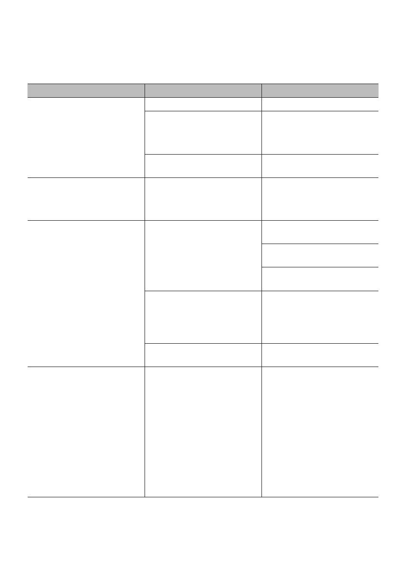
Problem Possible cause Remedy
Unit does not work. Battery voltage lower than 10 V. Replace or charge the battery.
The power demand of the connected
device is too high.
Disconnect external device. The
maximum power requirement should
not exceed the rated power of the
voltage converter.
Unit operation has been interrupted
by one of its protection systems.
See the relevant chapter ( Technical
Features).
Low voltage alarm is always on. Voltage or power are not sufficient
to power the inverter.
Check connections and verify whe-
ther is a problem caused by cables
(not clean or damaged) or the clips.
Low output voltage. Input voltage too low - Low voltage-
protection.
Switch off the power inverter imme-
diately.
Check connection and recharge
battery.
If voltage is higher than 11 V restart
the power inverter.
Polarity, incorrect connections, short-
circuit protection.
Switch off the power inverter
immediately. Disconnect all external
appliances. Check all connections,
cables and external appliances.
Adjust where necessary.
Rated power above max. Rated
power - overload protection.
Reduce the total power of connected
devices to the max. power rating.
TV operation and / or Audio systems
and / or external appliances
Snow image
image not steady
Humming, booming and whirring
sound audible
TV interference. Place power inverter as far away
from TV set as possible.
Check aerial connection and setting.
Place aerial cable away from power
inverter. Use a shielded aerial cable.
The modified sine wave of the power
inverter cannot be filtered sufficiently
by the connected external appliance.
Disconnect all cables immediately.
The only available solution is to use
a more modern external appliance
or one with a higher rating with
adequate filtering capability.
GB
29
CLEANING, CARE AND MAINTENANCE
Always disconnect the power inverter from the 12 V socket and the external appliance from the socket before starting
any cleaning or maintenance.
Keep all air inlets and vents free of dirt and dust. Clean the power inverter with a moistened cloth.
Do not use abrasive utensils for cleaning.
Store the power inverter in a dry place, well ventilated and in a temperature range between 0˚C and 40˚C.
Do not store in direct sunlight, near heaters, radiators or under moist and wet environmental conditions.
Service
Should you have any questions regarding commissioning or operating in spite of studying these operating instructions,
or if a problem should occur against all expectations, please get in contact with your specialist supplier..
Disposal
The packaging consists of non-contaminating materials that you can dispose of at your local recycling point.
Do not throw electrical appliances in with domestic waste! In accordance with European Directive 2002 /
96 / EC for waste electrical and electronic equipment (WEEE) and conversion to national law, used electrical
appliances must be collected separately and taken to a recycling point. For ways to dispose of old electrical appliances
please contact your community or city administration.
Illustrations may vary slightly from the product itself. We reserve the right to modify the product in accordance with
technical advances. Decoration not included.














  • Page 1 1
  • Page 2 2
  • Page 3 3
  • Page 4 4
  • Page 5 5
  • Page 6 6
  • Page 7 7
  • Page 8 8
  • Page 9 9
  • Page 10 10
  • Page 11 11
  • Page 12 12
  • Page 13 13
  • Page 14 14
  • Page 15 15
  • Page 16 16
  • Page 17 17
  • Page 18 18
  • Page 19 19
  • Page 20 20
  • Page 21 21
  • Page 22 22
  • Page 23 23
  • Page 24 24
  • Page 25 25
  • Page 26 26
  • Page 27 27
  • Page 28 28
  • Page 29 29
  • Page 30 30
  • Page 31 31
  • Page 32 32
  • Page 33 33
  • Page 34 34
  • Page 35 35
  • Page 36 36
  • Page 37 37
  • Page 38 38
  • Page 39 39
  • Page 40 40
  • Page 41 41
  • Page 42 42
  • Page 43 43
  • Page 44 44
  • Page 45 45
  • Page 46 46
  • Page 47 47
  • Page 48 48
  • Page 49 49
  • Page 50 50
  • Page 51 51
  • Page 52 52
  • Page 53 53
  • Page 54 54
  • Page 55 55
  • Page 56 56
  • Page 57 57
  • Page 58 58
  • Page 59 59
  • Page 60 60
  • Page 61 61
  • Page 62 62
  • Page 63 63
  • Page 64 64
  • Page 65 65
  • Page 66 66
  • Page 67 67
  • Page 68 68
  • Page 69 69
  • Page 70 70
  • Page 71 71
  • Page 72 72
  • Page 73 73
  • Page 74 74
  • Page 75 75
  • Page 76 76
  • Page 77 77
  • Page 78 78
  • Page 79 79
  • Page 80 80
  • Page 81 81
  • Page 82 82
  • Page 83 83
  • Page 84 84
  • Page 85 85
  • Page 86 86
  • Page 87 87
  • Page 88 88

AEG ST 500 97115 Owner's manual

Category
Voltage transformers
Type
Owner's manual

Ask a question and I''ll find the answer in the document

Finding information in a document is now easier with AI