Amprobe LT-10 Lamp Tester User manual
- Category
- Cable network testers
- Type
- User manual
This manual is also suitable for

LT-10
LT-10-EUR
Lamp Tester
ENG GER
ITA
User Manual
SPA FRE
SWE
Page is loading ...

English
LT-10
LT-10-EUR
Leakage Clamp Meter
User Manual
6/2018, 6000765 B
©2018 Amprobe
All rights reserved. Printed in China

Limited Warranty and Limitation of Liability
Your Amprobe/Beha-Amprobe product will be free from defects in material and workmanship
for one year from the date of purchase unless local laws require otherwise. This warranty does
not cover fuses, disposable batteries or damage from accident, neglect, misuse, alteration,
contamination, or abnormal conditions of operation or handling. Resellers are not authorized to
extend any other warranty on the behalf of Amprobe/Beha-Amprobe. To obtain service during
the warranty period, return the product with proof of purchase to an authorized Amprobe/
Beha-Amprobe Service Center or to an Amprobe/Beha-Amprobe dealer or distributor. See
Repair Section for details. THIS WARRANTY IS YOUR ONLY REMEDY. ALL OTHER WARRANTIES -
WHETHER EXPRESS, IMPLIED OR STATUTORY - INCLUDING IMPLIED WARRANTIES OF FITNESS FOR
A PARTICULAR PURPOSE OR MERCHANTABILITY, ARE HEREBY DISCLAIMED. MANUFACTURER
SHALL NOT BE LIABLE FOR ANY SPECIAL, INDIRECT, INCIDENTAL OR CONSEQUENTIAL DAMAGES
OR LOSSES, ARISING FROM ANY CAUSE OR THEORY. Since some states or countries do not allow
the exclusion or limitation of an implied warranty or of incidental or consequential damages, this
limitation of liability may not apply to you.
Repair
All Amprobe/Beha-Amprobe returned for warranty or non-warranty repair or for calibration should be
accompanied by the following: your name, company’s name, address, telephone number, and proof of
purchase. Additionally, please include a brief description of the problem or the service requested and
include the test leads with the meter. Non-warranty repair or replacement charges should be remitted
in the form of a check, a money order, credit card with expiration date, or a purchase order made
payable to Amprobe/Beha-Amprobe.
In-Warranty Repairs and Replacement – All Countries
Please read the warranty statement and check your battery before requesting repair. During the
warranty period, any defective test tool can be returned to your Amprobe/Beha-Amprobe distributor
for an exchange for the same or like product. Please check the “Where to Buy” section on amprobe.
com or beha-amprobe.com for a list of distributors near you. Additionally, in the United States and
Canada, in-warranty repair and replacement units can also be sent to an Amprobe/Beha-Amprobe
Service Center (see address below).Service Center (see address below).
Non-warranty Repairs and Replacement – United States and Canada
Non-warranty repairs in the United States and Canada should be sent to an Amprobe Service
Center. Call Amprobe or inquire at your point of purchase for current repair and replacement rates.
USA: Canada:
Amprobe Amprobe
Everett, WA 98203 Mississauga, ON L4Z 1X9
Tel: 877-AMPROBE (267-7623) Tel: 905-890-7600
Non-Warranty Repairs and Replacement – Europe
European non-warranty units can be replaced by your Beha-Amprobe distributor for a nominal
charge. Please check the “Where to Buy” section on beha-amprobe.com for a list of distributors near
you.
Beha-Amprobe
Division and reg. trademark of Fluke Corp. (USA)
Germany* United Kingdom The Netherlands - Headquarters**
In den Engematten 14 52 Hurricane Way Science Park Eindhoven 5110
79286 Glottertal Norwich, Norfolk 5692 EC Son
Germany NR6 6JB United Kingdom The Netherlands
Tel.: +49 (0) 7684 8009 - 0 Tel.: +44 (0) 1603 25 6662 Tel.: +31 (0) 40 267 51 00
beha-amprobe.de beha-amprobe.com beha-amprobe.com
*(Correspondence only – no repair or replacement available from this address. European customers please
contact your distributor.)
**single contact address in EEA Fluke Europe BV

1
LT-10 / LT-10-EUR Lamp Tester
CONTENTS
SYMBOL .......................................................................................................3
SAFETY INFORMATION ...............................................................................3
UNPACKING AND INSPECTION ...................................................................4
FEATURE .......................................................................................................4
OPERATING THE LAMP TESTER ..................................................................5
Attaching and Removing the Antenna .................................................6
Attaching and Removing the Adaptor ..................................................7
LAMP TEST ..............................................................................................7
Testing Fluorescent Lamps .....................................................................8
Using Sodium Lamp Antenna ................................................................9
VolTect™ Non-contact Voltage Detection ............................................10
Voltage Detection with Antenna ..........................................................11
Voltage Detection with Probe ...............................................................12
Pin Test ....................................................................................................13
DETAILED SPECIFICATIONS .........................................................................14
MAINTENANCE ............................................................................................15
TROUBLESHOOTING ....................................................................................16
BATTERY REPLACEMENT ............................................................................. 17

2
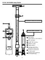
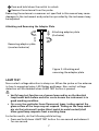
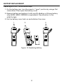
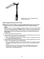
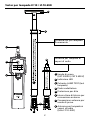
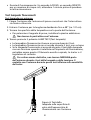
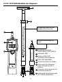
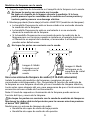
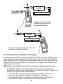
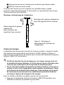
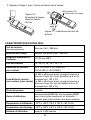
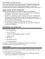
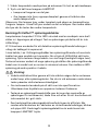
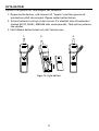
For lamp test only!
Do not use with live voltage.
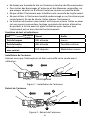
1
1
2
4
8
5
7
8
3
2
3
4
5
6
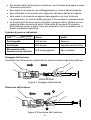
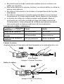
Test probe
(CAT III 300 V, CAT II 600 V)
LED indicator
LAMP TEST button
Adaptor plate
Finger guard
Locking switch for
antenna connection
Antenna connection
to test probe
Sodium lamp antenna
(LT-10-EUR only)
Fluorescent lamp test antenna
Sodium Lamp Antenna
LT-10 / LT-10-EUR Lamp Tester
6
7

3
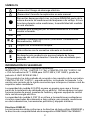
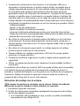
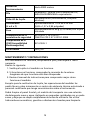
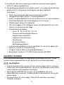
SYMBOLS
Caution! Risk of electric shock.
W
Caution! Refer to the explanation in this manual.
To avoid electric shock, do not touch ANY part of antenna
during lamp or voltage tests. Touching antenna during these
tests affects tester sensitivity.
T
The equipment is protected by double insulation or reinforced
insulation.
N
Battery.
)
Canadian Standards Association (NRTL/C)
P
Complies with European Directives.
Conforms to relevant Australian standards.
=
Do not dispose this product as unsorted municipal waste.
Contact aqualified recycler.
SAFETY INFORMATION
The meter complies with:
IEC/EN 61010-1 3rd Ed., UL61010-1 2nd Ed. and CAN/CSA C22.2 No. 61010-1-
04 + CSA Update No.1: 2008 to CAT II 300 V, CAT I 600 V, pollution degree 2.
EMC IEC/EN 61326-1
“This product has been tested to the requirements of CAN/CSA-C22.2
No.61010-1, second edition, including Amendment 1, or a later version of
the same standard incorporating the same level of testing requirements.”
Measurement category lll (CAT III) is for equipment intended to form part of
a building wiring installation. Such equipment includes socket receptacles,
fuse panels, and some mains installation control equipment.
Measurement Category II (CAT II) is for measurements performed on
circuits directly connected to low voltage; for example, measurements on
household appliances, portable tools and similar equipment.
CENELEC Directives
The instruments conform to CENELEC low voltage directive 2006/95/EC and
electromagnetic compatibility directive 2004/108/EC

4
For Use by Competent Persons
Anyone using this instrument should be knowledgeable and trained about
the risks involved with light fixtures and electrical connections. They must
understand the importance of taking safety precautions and testing the
instrument before and after use to ensure that it is in good working condition.
W Warning: Read Before Using
To avoid possible electric shock or personal injury:
• If the tester is used in a manner not specified by the manufacturer,
protection provided by the tester may be impaired.
• For indoor use only. Do not use the tester in rain, snow, damp or wet
locations. Do not use the tester around explosive gas or vapor. Do not
insert or remove the battery in an explosive or flammable environment.
• Comply with local and national safety requirements.
• Use proper protective equipment as required by local or national
authorities.
UNPACKING AND INSPECTION
Your shipping carton should include:
1 LT-10 Lamp Tester
1 Fluorescent lamp antenna
1 Sodium lamp antenna (LT-10-EUR only)
1 Adaptor plate
1 Carrying case
1 9V alkaline battery
1 Users manual
If any of these items are damaged or missing, return the complete package
to the place of purchase for an exchange.
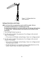
FEATURES
The Amprobe LT-10 Lamp Tester is a pocket-sized tool designed to
troubleshoot fluorescent lamps prior to installation or removal and verify
presence of voltage of electrical systems.
Three easy steps to troubleshoot lamps:
1. Check if fluorescent (electroluminescent) light bulb is damaged with
LAMP TEST and PIN TEST functions.

5
2. Verify if voltage is present at the ballast with VolTect™ non-contact
voltage detection.
3. If light bulb passes the test in step 1 and the voltage is present in step 2,
but the lamp is not working, then replace the ballast.
Features:
• Tests fluorescent (electroluminescent) lights
• Built-in VolTect™ non-contact voltage detection
• Lamp and filament test to check fluorescent and sodium light bulbs
• Simple one-handed, single button operation
• Ultra-compact design for portability
• 48” removable, fully retractable antenna included to test lights and
voltage without a ladder
• Compatible with light bulbs:
- Fluorescent T2, T4, T5, T8, T9, T10, T12 light bulbs
- Fluorescent energy saving light bulbs
- Low pressure sodium vapor bulbs
- High prossure sodium vapor bulbs
- Neon bulbs
- Mercury vapor bulbs
- Halogen metal vapor bulbs
• Insulated antenna sleeve and tip provided to safely extend and
retract during use
• Does not work with LED and incandescent (standard) light bulbs
• Replacement parts: Antenna LT-10-ANT (Item No. 4357839)
OPERATING THE TESTER
The test probe and antennas emit a high frequency voltage (approximately
3 kV) to ionize the light fixtures in order to diagnose a failure.
W Precautions:
• To avoid electric shock, do not touch ANY part of antenna during lamp
or voltage tests. Touching antenna during these tests affects tester
sensitivity.
• When LAMP TEST button is pressed, be alert. Do not touch test probe
or antenna. Discharge can cause electric shock or personal injury.
• Do not attempt to overreach. Make sure you have proper footing and
balance at all times.

6
• Do not allow lamp test probe or antenna to touch energized wires.
• To avoid damages to antenna and personal injury, do not attempt to
bend or use the antenna as a crowbar.
• Do not operate the instrument if the case or the battery door is open.
• Do not use if the instrument appears damaged or doesn’t operate
properly. If in doubt, have the instrument serviced.
• The non-contact voltage function is always on. Test on a known live
source within the rated ac voltage range of the product, both before
and after use to ensure the instrument is in good working condition.
Test Functions and Indications:
Visual Audio
Lamp test LED on None
Pin test LED on Solid tone
Non-contact voltage detection LED flashing Modulated beep
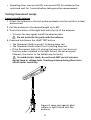
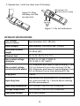
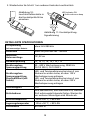
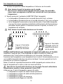
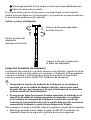
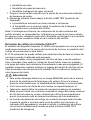
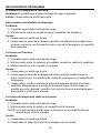
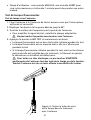
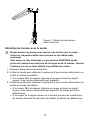
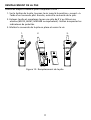
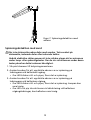
Attaching the Antenna
Make sure the switch is securely locked onto the probe before use.
Switch
Figure 1: Attaching the antenna
Removing the Antenna
1
2
Figure 2: Removing the antenna
Indication
Test

7
1
Press and hold down the switch to unlock.
2
Remove the antenna from the probe.
Removing the antenna in a manner not specified in this manual may cause
damages to the instrument and protection provided by the instrument may
be impaired.
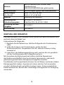
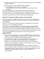
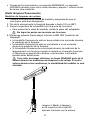
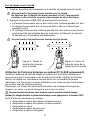
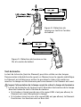
Attaching and Removing the Adapter Plate
Figure 3: Attaching and
removing the adapter plate
Attaching adaptor plate
(clockwise)
Removing adaptor plate
(counterclockwise)
LAMP TEST
Non-contact voltage detection is always on. When the probe or the antenna
is close to energized wires, LED flashes and beeps. Non-contact voltage
detection will be disabled when LAMP TEST button is pressed.
W
• Verify lamp test function on a known lamp and/or on the identical
lamp model both before and after use to ensure the instrument is in
good working condition.
• On a very few particular linear fluorescent types, testing against the
glass surface of the lamp may not respond. Testing on the lamp socket
pin via the instrument’s probe (direct metal-to-metal contact) shall
allow good lamp response from a working lamp.
For better results, do the following while testing:
• Press and hold down LAMP TEST button for one second and release it
for one second.

8
• Operating time: one second ON, one second OFF for maximum five
cycles and wait for 1 minute before taking another measurement.
Testing Fluorescent Lamps
Lamp test with antenna
1. Attach the antenna to the test probe and make sure the switch is locked
and secured.
2. Pull the antenna to the desired length up to 48”.
3. Touch the surface of the light bulb with the tip of the antenna.
• To boost the test signal, install the adapter plate.
Do not touch the live parts with the antenna.
4. Press and hold down the LAMP TEST button
• The fluorescent bulb is good if lit during lamp test
• The fluorescent bulb is bad if not lit during lamp test
• If the fluorescent bulb is lit during the lamp test, but does not
function when installed in the light fixture, the spiral wound
filament, the starter or the ballast may be faulty.
To avoid electric shock, do not touch ANY part of antenna
during lamp or voltage tests. Touching antenna during these tests
affects tester sensitivity.
Figure 4: Lamp test against glass
surface in light fixture with the
antenna

9
Lamp test with the probe
1. Touch the surface of the light bulb or the lamp socket with the probe.
Do not touch energized parts with the probe.
Do not touch the lamp socket during test. This could lead to faulty
test results and cause electric shock.
2. Press and hold down the LAMP TEST button.
• The fluorescent bulb is good if lit during lamp test
• The fluorescent bulb is bad if not lit during lamp test
• If the fluorescent bulb is lit during the lamp test, but does not
function when installed in the light fixture, the spiral wound
filament, the starter or the ballast may be faulty.
Do not touch the live parts with the probe.
Figure 6: Lamp test
against glass surface
with the probe
Figure 5: Lamp test
against socket with
the probe
Using Sodium Lamp Antenna (LT-10-EUR only)
Install the sodium lamp test antenna onto the Lamp Tester and make sure
the switch is locked and secured. Verify lamp test function on a known lamp
and/or on the identical lamp model both before and after use to ensure the
instrument is in good working condition.
Note: The level of lamp response/illumination from one lamp type to
another or from one brand to another may vary.
Do not touch the live parts with the lamp test probe. Keep the fingers
behind the hand guard while TEST button is pressed.
Sodium lamp antenna tests:
• Low pressure sodium vapor bulbs
• High prossure sodium vapor bulbs
• Neon bulbs
• Mercury vapor bulbs
• Halogen metal vapor bulbs

10
1. Touch the one of the socket pin with the tip of the sodium lamp test
antenna.
2. Press and hold down the LAMP TEST button
• The bulbs is good if glowing.
• If the bulb does not glow, repeat lamp test with touching the other
socket pin.
Note: If the bulb glows with either of socket pins during lamp test, the
lamp is good. In some cases, only part of the bulb will glow, the other part
should glow when testing the other socket pin.
VolTect™ Non-contact Voltage Detection
Amprobe LT-10 Lamp Tester is NOT equipped with a probe tip to be inserted
into the slot of the receptacle contact. Testing voltage that way will not be
reliable.
The LT-10 can only be used for detecting hot wires in outlets when the
wiring is exposed.
With some cables, such as extension cords, hot and neutral wires might be
twisted. In order to reliably test voltage, move the tester along the cable for
some distance (typically a few inches). The tester will only indicate voltage
in places where the hot wire of the twisted wires is closer to the tester. It
will NOT indicate voltage in other places of the cable.
W WARNING!
• To avoid electric shock, do not touch ANY part of antenna during lamp
or voltage tests. Touching antenna during these tests affects tester
sensitivity.
• If the instrument is used in a manner not specified by the manufacturer,
protection provided by the tester may be impaired.
• Test on a known energized source within the rated ac voltage range of
the instrument both before and after use to ensure the instrument is in
good working condition.
• The non-contact voltage detection function is always on. When the
probe or antenna is close to energized wires, LED flashes and beeps.
Non-contact voltage detection will be disabled when the LAMP TEST
button is pressed.

11
• When using the instrument, if LED indicator does not glow or
the instrument does not beep, voltage could still be present. The
instrument indicates active voltage in the presence of electrostatic
fields of sufficient strength generated from the source voltage. If the
field strength is low, the instrument may not provide indication of live
voltage. Lack of an indication occurs if the instrument is unable to sense
the presence of voltage which may be influenced by several factors
including, but not limited to:
- Shielded wire/cables
- Thickness and type of insulation
- Distance from the voltage source
- Fully-isolated users that prevent an effective ground
- Receptacles in recessed sockets or differences in socket design
- Condition of the instrument and batteries
• Do not use if the instrument appears damaged or if it doesn’t operate
properly. Closely examine the tip of the probe for cracks or breakage
before use. If in doubt, have the instrument serviced.
• Do not use the instrument to test voltage higher than the rated voltage
as marked on the instrument.
• Use caution with voltages above 30 V ac as a shock hazard may exist.
• Comply with local and national safety requirements.
• Use proper protective equipment as required by local or national
authorities.
The non-contact voltage (NCV) test can be used to check whether the
ballast is functional by verifying the presence of ac voltages at the input
and output of the ballast, or the energized parts of the light fixture. The
light fixture must be turned on before verifying the presence of ac voltage
with the instrument.
Voltage Detection with Antenna
Do not touch the energized bare parts with the antenna. Test on
energized insulated parts or insulated wires only.
1. Turn the light fixture’s power on.
2. Use the antenna to quickly check the presence of ac voltage to the light
fixture.
• If the LED flashes red and beeps (modulated), there is ac voltage
present.

12
Figure 7: Voltage detection
with antenna
Voltage Detection with Probe
Do not touch the energized bare parts with the probe. Test on
energized insulated parts or insulated wires only.
To avoid electric shock, do not touch ANY part of antenna during lamp
or voltage tests. Touching antenna during these tests affects tester
sensitivity.
1. Turn the light fixture’s power on.
2. Use the probe to detect the presence of ac voltage on the wires at
input of the ballast.
• If the tester’s LED flashes red and beeps, there is ac voltage present.
3. Use the probe to detect the presence of ac voltage on the wires at
output of the ballast.
• If the tester’s LED flashes red and beeps, there is ac voltage present.
The lamp may be faulty.
• If LED and beeper do not activate during voltage detection at the
ballast output wires, the ballast may be faulty.

13
Figure 8: Voltage detection
at ballast input wires
Figure 9: Voltage detection at ballast
output wires
Pin Test
The pin test (filament test) can be used on dual pin fluorescent lamps that
have a filament under the metal cap. The filament is used to excite the gas
inside the tube and turn it on. The lamp will not function correctly if the
filament is broken.
Turn the power off to the light fixture before removing the lamp from
the fixture.
1. Pin test is always on. Plug the lamp pins into the pin test slots on the
back of the tester.
• If the tester does not beep and LED indicator is not on, the filament
is broken. Replace the lamp.
• If the tester beeps and LED indicator is on, the filament is functional.
The pins are good.

14
2. Repeat step 1 with the other end of the lamp.
Figure 10: Plug
the lamp into the
pin test slots
LED indicator ON
Solid continuous beep
Figure 11: Pin test indications
DETAILED SPECIFICATIONS
Test voltage
(with new battery)
Approximately 3 kV / 280 kHz
Field strength Approximately 100 μV/m at 260 - 300 kHz
Maximum antenna
length
121.92cm (48”)
Filament test T2, T4, T5, T8, T9, T10, T12
Non-contact voltage
detection
AC 90 V to AC 600 V, 50/60 Hz
CAT III 300 V, CAT II 600 V
Non-contact voltage
sensitivity (with probe)
LED illuminates and beeps at approximately 3 mm
(0.12 in) distance from a wire carrying 120 Vac
LED illuminates and beeps at approximately 5 mm
(0.2 in) distance from a wire carrying 230 Vac
Drop proof 1 meter
Operating time
One second ON, one second OFF for maximum
five cycles and wait for 1 minute before making
another measurement
Operating temperature -10
O
C to +50
O
C (14
O
F to 122
O
F) ≤85% RH
Storage temperature -10
O
C to +50
O
C (14
O
F to 122
O
F) ≤85% RH
Operating altitude Up to 2000 meters

15
Battery
1 x 9V lithium or alkaline battery only,
6LR61/6LF22/MN1604 or equivalent
Battery life 500 tests (alkaline typically)
Dimensions
(L x W x H)
Approximately 170 x 40 x 24 mm
(6.69 x 1.57 x 0.94 in)
Weight
Approximately 80 g (0.18 lb)
with battery installed
Safety compliance
IEC 61010-1, UL 61010-1
CAN/CSA-C22.2 No. 61010-1-2004
EMC compliance IEC 61326-1
Certification CSA and CE
MAINTENANCE AND REPAIR
If the instrument fails to operate, check the battery and replace as
necessary.
Do the following:
1. Replace the battery if the tester does not work.
2. If antenna is not working, check the antenna connection. Make sure the
antenna is locked and secured.
3. Review the users manual to better understand how the tester operates.
Except for the replacement of the battery, repair of the tester should
be performed only by an authorized service center or by other qualified
instrument service personnel.
The front panel and carrying case can be cleaned with a mild solution of
detergent and water. Apply sparingly with a soft cloth and allow to dry
completely before using. Do not use aromatic hydrocarbons, gasoline or
chlorinated solvents for cleaning.

16
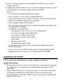
TROUBLESHOOTING
Lamp tester doesn’t work:
Problem: Possible low or dead battery
Action: Check and/or replace battery
Low lamp tester response:
Problem:
1. Possible low battery
2. Bad contact between the probe/antenna and the lamp tester
Action:
1. Check and/or replace battery
2. Test the area on the lamp where the probe/antenna can make good
contact against lamp glass surface or the lamp socket
Antenna doesn’t work:
Problem:
1. Possible low battery
2. Bad contact between the antenna and the lamp under test
3. Bad connection contact between the probe and antenna
Action:
1. Check and/or replace battery
2. Test the area on the lamp where the antenna can make good contact
against lamp glass surface or the lamp socket
3. Check and re-install the antenna. Make sure the antenna is securely
locked onto the probe. If the antenna is still not working, the
antenna may be damaged. Contact a service center for repair or
antenna replacement
Sodium lamp antenna doesn’t work:
Problem:
1. Possible low battery
2. Bad contact between the probe and the lamp socket
NOTE: The insulated probe may not work on socket of energy saving
lamp.
Action:
1. Check and/or replace battery
2. Test the glass tube on the lamp with the probe.

17
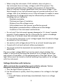
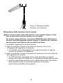
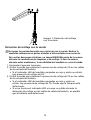
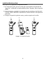
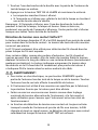
BATTERY REPLACEMENT
Replacing BATTERY follow below steps:
1. On the battery case, turn the screw to “open” position by using a flat
screw driver. Then open the battery cover.
2. Remove battery and replace it with one 9V alkaline or lithium battery
only (6LF22, 6LR61, MN1604 or equivalent). Pay attention to the
polarity signs.
3. Put the battery cover back on and refasten the screw.
1. 2. 3.
Figure 12: Replacing battery
Page is loading ...
Page is loading ...
Page is loading ...
Page is loading ...
Page is loading ...
Page is loading ...
Page is loading ...
Page is loading ...
Page is loading ...
Page is loading ...
Page is loading ...
Page is loading ...
Page is loading ...
Page is loading ...
Page is loading ...
Page is loading ...
Page is loading ...
Page is loading ...
Page is loading ...
Page is loading ...
Page is loading ...
Page is loading ...
Page is loading ...
Page is loading ...
Page is loading ...
Page is loading ...
Page is loading ...
Page is loading ...
Page is loading ...
Page is loading ...
Page is loading ...
Page is loading ...
Page is loading ...
Page is loading ...
Page is loading ...
Page is loading ...
Page is loading ...
Page is loading ...
Page is loading ...
Page is loading ...
Page is loading ...
Page is loading ...
Page is loading ...
Page is loading ...
Page is loading ...
Page is loading ...
Page is loading ...
Page is loading ...
Page is loading ...
Page is loading ...
Page is loading ...
Page is loading ...
Page is loading ...
Page is loading ...
Page is loading ...
Page is loading ...
Page is loading ...
Page is loading ...
Page is loading ...
Page is loading ...
Page is loading ...
Page is loading ...
Page is loading ...
Page is loading ...
Page is loading ...
Page is loading ...
Page is loading ...
Page is loading ...
Page is loading ...
Page is loading ...
Page is loading ...
Page is loading ...
Page is loading ...
Page is loading ...
Page is loading ...
Page is loading ...
Page is loading ...
Page is loading ...
Page is loading ...
Page is loading ...
Page is loading ...
Page is loading ...
Page is loading ...
Page is loading ...
Page is loading ...
Page is loading ...
Page is loading ...
Page is loading ...
Page is loading ...
Page is loading ...
Page is loading ...
Page is loading ...
Page is loading ...
Page is loading ...
Page is loading ...
Page is loading ...
Page is loading ...
Page is loading ...
Page is loading ...
Page is loading ...
Page is loading ...
-
 1
1
-
 2
2
-
 3
3
-
 4
4
-
 5
5
-
 6
6
-
 7
7
-
 8
8
-
 9
9
-
 10
10
-
 11
11
-
 12
12
-
 13
13
-
 14
14
-
 15
15
-
 16
16
-
 17
17
-
 18
18
-
 19
19
-
 20
20
-
 21
21
-
 22
22
-
 23
23
-
 24
24
-
 25
25
-
 26
26
-
 27
27
-
 28
28
-
 29
29
-
 30
30
-
 31
31
-
 32
32
-
 33
33
-
 34
34
-
 35
35
-
 36
36
-
 37
37
-
 38
38
-
 39
39
-
 40
40
-
 41
41
-
 42
42
-
 43
43
-
 44
44
-
 45
45
-
 46
46
-
 47
47
-
 48
48
-
 49
49
-
 50
50
-
 51
51
-
 52
52
-
 53
53
-
 54
54
-
 55
55
-
 56
56
-
 57
57
-
 58
58
-
 59
59
-
 60
60
-
 61
61
-
 62
62
-
 63
63
-
 64
64
-
 65
65
-
 66
66
-
 67
67
-
 68
68
-
 69
69
-
 70
70
-
 71
71
-
 72
72
-
 73
73
-
 74
74
-
 75
75
-
 76
76
-
 77
77
-
 78
78
-
 79
79
-
 80
80
-
 81
81
-
 82
82
-
 83
83
-
 84
84
-
 85
85
-
 86
86
-
 87
87
-
 88
88
-
 89
89
-
 90
90
-
 91
91
-
 92
92
-
 93
93
-
 94
94
-
 95
95
-
 96
96
-
 97
97
-
 98
98
-
 99
99
-
 100
100
-
 101
101
-
 102
102
-
 103
103
-
 104
104
-
 105
105
-
 106
106
-
 107
107
-
 108
108
-
 109
109
-
 110
110
-
 111
111
-
 112
112
-
 113
113
-
 114
114
-
 115
115
-
 116
116
-
 117
117
-
 118
118
-
 119
119
-
 120
120
-
 121
121
-
 122
122


Amprobe LT-10 Lamp Tester User manual
- Category
- Cable network testers
- Type
- User manual
- This manual is also suitable for
Ask a question and I''ll find the answer in the document
Finding information in a document is now easier with AI
in other languages
Related papers
-
Amprobe FLASH-175 User manual
-
Amprobe BAT-250 User manual
-
-
Amprobe VPC-12 User manual
-
-
-
-
Amprobe IRC-110 Thermal Camera User manual
-
-
Other documents
-
 BEHA AMPROBE BAT-250-EUR Battery Tester User manual
-
Fluke 4472387 User guide
-
HOMCOM B31-318 User guide
-
-
 Kichler Lighting 4822BK User manual
-
-
Hay Neon Tube User manual
-
Robin AMPROBE KMP7020 User manual
-
Ampro 88-6 User manual
-
Milwaukee 2210-20 User manual

