EuroLite LED IP PAR 12x3W TCL User manual
- Category
- Stroboscopes & disco lights
- Type
- User manual
This manual is also suitable for

©
Copyright
Nachdruck verboten!
Reproduction prohibited!
Für weiteren Gebrauch aufbewahren!
Keep this manual for future needs!
BEDIENUNGSANLEITUNG
USER MANUAL
LED IP PAR 36x1W RGB/
LED IP PAR 12x3W TCL
LED Outdoor Floorspot

00063704.DOC, Version 1.12/23
MULTI-LANGUAGE-INSTRUCTIONS
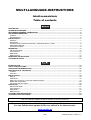
Inhaltsverzeichnis
Table of contents
EINFÜHRUNG................................................................................................................................................... 3
SICHERHEITSHINWEISE................................................................................................................................. 3
BESTIMMUNGSGEMÄßE VERWENDUNG..................................................................................................... 5
GERÄTEBESCHREIBUNG............................................................................................................................... 6
Features ......................................................................................................................................................... 6
Geräteübersicht.............................................................................................................................................. 6
INSTALLATION ................................................................................................................................................ 7
Montage ......................................................................................................................................................... 7
Befestigung .................................................................................................................................................... 7
Anschluss an den DMX-512 Controller / Verbindung Gerät – Gerät ............................................................. 8
Master/Slave-Betrieb...................................................................................................................................... 9
Anschluss ans Netz........................................................................................................................................ 9
BEDIENUNG ..................................................................................................................................................... 9
Stand Alone-Mode ....................................................................................................................................... 10
Control Board ............................................................................................................................................... 10
DMX-Mode ................................................................................................................................................... 11
DMX-Protokoll .............................................................................................................................................. 12
REINIGUNG UND WARTUNG........................................................................................................................ 12
TECHNISCHE DATEN .................................................................................................................................... 13
INTRODUCTION ............................................................................................................................................. 14
SAFETY INSTRUCTIONS............................................................................................................................... 14
OPERATING DETERMINATIONS.................................................................................................................. 16
DESCRIPTION OF THE DEVICE ................................................................................................................... 17
Features ....................................................................................................................................................... 17
Overview ...................................................................................................................................................... 17
INSTALLATION .............................................................................................................................................. 18
Rigging ......................................................................................................................................................... 18
Attachment ................................................................................................................................................... 18
DMX-512 connection / connection between fixtures.................................................................................... 19
Master/Slave-Operation ............................................................................................................................... 20
Connection with the mains........................................................................................................................... 20
OPERATION.................................................................................................................................................... 20
Stand Alone-Mode ....................................................................................................................................... 21
Control Board ............................................................................................................................................... 21
DMX-Mode ................................................................................................................................................... 22
DMX-Protocol............................................................................................................................................... 22
CLEANING AND MAINTENANCE ................................................................................................................. 23
TECHNICAL SPECIFICATIONS..................................................................................................................... 23
Diese Bedienungsanleitung gilt für die Artikelnummern: 51914174, 51914175
This user manual is valid for the article numbers: 51914174, 51914175
Das neueste Update dieser Bedienungsanleitung finden Sie im Internet unter:
You can find the latest update of this user manual in the Internet under:
www.eurolite.de
Page is loading ...
Page is loading ...
Page is loading ...
Page is loading ...
Page is loading ...
Page is loading ...
Page is loading ...
Page is loading ...
Page is loading ...
Page is loading ...
Page is loading ...

00063704.DOC, Version 1.1
14/23
USER MANUAL
LED IP PAR 36x1W RGB/
LED IP PAR 12x3W TCL
LED-Outdoor-Floorspot
CAUTION!
Unplugmainsleadbeforeopeningthehousing!
For your own safety, please read this user manual carefully before you initially start-up.
Every person involved with the installation, operation and maintenance of this device has to
- be qualified
- follow the instructions of this manual
- consider this manual to be part of the total product
- keep this manual for the entire service life of the product
- pass this manual on to every further owner or user of the product
- download the latest version of the user manual from the Internet
INTRODUCTION
Thank you for having chosen a EUROLITE LED IP PAR 36x1W RGB/LED IP PAR 12x3W TCL. If you follow
the instructions given in this manual, we are sure that you will enjoy this device for a long period of time.
Unpack your device.
SAFETY INSTRUCTIONS
CAUTION!
Becarefulwithyouroperations.Withadangerousvoltageyoucansufferadangerous
electricshockwhentouchingthewires!
This device has left our premises in absolutely perfect condition. In order to maintain this condition and to
ensure a safe operation, it is absolutely necessary for the user to follow the safety instructions and warning
notes written in this user manual.

00063704.DOC, Version 1.1
15/23
Important:
Damages caused by the disregard of this user manual are not subject to warranty. The dealer
will not accept liability for any resulting defects or problems.
If the device has been exposed to drastic temperature fluctuation (e.g. after transportation), do not switch it
on immediately. The arising condensation water might damage your device. Leave the device switched off
until it has reached room temperature.
Please make sure that there are no obvious transport damages. Should you notice any damages on the A/C
connection cable or on the casing, do not take the device into operation and immediately consult your local
dealer.
This device falls under protection-class I. The power plug must only be plugged into a protection class I
outlet. The voltage and frequency must exactly be the same as stated on the device. Wrong voltages or
power outlets can lead to the destruction of the device and to mortal electrical shock.
Always plug in the power plug last. The power plug must always be inserted without force. Make sure that
the plug is tightly connected with the outlet.
Never let the power-cord come into contact with other cables! Handle the power-cord and all connections
with the mains with particular caution! Never touch them with wet hands, as this could lead to mortal
electrical shock.
Never modify, bend, strain mechanically, put pressure on, pull or heat up the power cord. Never operate next
to sources of heat or cold. Disregard can lead to power cord damages, fire or mortal electrical shock.
The cable insert or the female part in the device must never be strained. There must always be sufficient
cable to the device. Otherwise, the cable may be damaged which may lead to mortal damage.
Make sure that the power-cord is never crimped or damaged by sharp edges. Check the device and the
power-cord from time to time.
If extension cords are used, make sure that the core diameter is sufficient for the required power
consumption of the device. All warnings concerning the power cords are also valid for possible extension
cords.
Always disconnect from the mains, when the device is not in use or before cleaning it. Only handle the
power-cord by the plug. Never pull out the plug by tugging the power-cord. Otherwise, the cable or plug can
be damaged leading to mortal electrical shock. If the power plug or the power switch is not accessible, the
device must be disconnected via the mains.
If the power plug or the device is dusty, the device must be taken out of operation, disconnected and then be
cleaned with a dry cloth. Dust can reduce the insulation which may lead to mortal electrical shock. More
severe dirt in and at the device should only be removed by a specialist.
There must never be any objects entering into the device. This is especially valid for metal parts. If any metal
parts like staples or coarse metal chips enter into the device, the device must be taken out of operation and
disconnected immediately. Malfunction or short-circuits caused by metal parts may cause mortal injuries.
HEALTHHAZARD!
Neverlookdirectlyintothelightsource,assensitivepersonsmaysufferan
epilepticshock(especiallymeantforepileptics)!
Keep away children and amateurs!
Never leave this device running unattended.

00063704.DOC, Version 1.1
16/23
OPERATING DETERMINATIONS
This device is a fixed general purpose luminaire. This product is only allowed to be operated with an
alternating voltage of 230 V, 50 Hz.
This device is jet-proof (IP65) and therefore qualified for indoor and outdoor use. In order to maintain this
protection grade after opening the housing, any rubber sealings must be examined for damages and always
be correctly installed.
For outdoor use, the installer must always make sure to connect a rubber cable H05RN-F or HO5RR-F. For
installations in the ground, an underground power cable NYY must be used!
All valid instructions concerning the installation of cables outdoors or in the ground must be adhered!
The ambient temperature must always be between -25° C and +45° C. Keep away from direct insulation
(particularly in cars) and heaters.
The maximum relative humidity is 100 % with an ambient temperature of 25° C.
This device must only be operated in an altitude between -20 and 2000 m over NN.
This device is designed for professional use.
Do not shake the device. Avoid brute force when installing or operating the device.
When choosing the installation-spot, please make sure that the device is not exposed to extreme heat,
moisture or dust. There should not be any cables lying around. You endanger your own and the safety of
others!
The maximum ambient temperature T
a
= 45° C must never be exceeded.
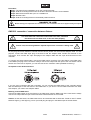
The F-symbol means: this device can be installed on normal inflammable surfaces.
Never use the device during thunderstorms. Over voltage could destroy the device. Always disconnect the
device during thunderstorms.
The symbol
---m
determines the minimum distance from lighted objects. The minimum distance
between light-output and the illuminated surface must be more than 0.1 meters.
This device is only allowed for an installation via the mounting bracket. In order to safeguard sufficient
ventilation, leave 50 cm of free space around the device.
The housing must never touch surrounding surfaces or objects.
Make sure that the area below the installation place is blocked when rigging, derigging or servicing the
fixture.
Only operate the fixture after having checked that the housing is firmly closed and all screws are tightly
fastened.
Operate the device only after having become familiarized with its functions. Do not permit operation by
persons not qualified for operating the device. Most damages are the result of unprofessional operation!
Never use solvents or aggressive detergents in order to clean the device! Rather use a soft and damp cloth.
Please use the original packaging if the device is to be transported. Make sure that you pack the device in
the original state.
Please consider that unauthorized modifications on the device are forbidden due to safety reasons!
Never remove the serial barcode from the device as this would make the guarantee void.
If this device will be operated in any way different to the one described in this manual, the product may suffer
damages and the guarantee becomes void. Furthermore, any other operation may lead to dangers like short-
circuit, burns, electric shock, crash etc.

00063704.DOC, Version 1.1
17/23
DESCRIPTION OF THE DEVICE
Features
LED outdoor floor spot
• 3 or 5 DMX channels selectable for numerous applications
• Locking possibility at the mounting bracket
• Ideal as floor spot via additional bracket
• RGB color change
• 7 color presets and 4 built-in programs
• DMX-controlled operation or stand-alone operation with Master/Slave function
• Dimmer and strobe settings via DMX
• Suitable for external use, IP 65
• Perfect for architectural lighting in public places and buildings
• Addressing via control panel with 4-digit LED display
• Control via control panel with display or any regular DMX controller
• Feed-through output allows to power another device
• After every 8 spot the fixtures must have a renewed connection with the power mains
EUROLITE LED IP PAR 36x1W RGB
• Equipped with 36 x 1 W LED: 12 x red, 12 x green and 12x blue
• Beam angle approximately 15°
EUROLITE LED IP PAR 12x3W TCL
• Equipped with 12 x 3 W tricolor LED
• Beam angle approximately 25°
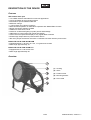
Overview
(1) Housing
(2) LEDs
(3) Fixation screw
(4) Mounting bracket
(5) Floor-stand

00063704.DOC, Version 1.1
18/23
(6) DMX input plug
(7) Power input
(8) Display
(9) Mode button
(10) Enter button
(11) Up button
(12) Down button
(13) Power output
(14) DMX out connectors
INSTALLATION
Rigging
The device can be placed directly on the stage floor or rigged in any orientation without altering its operation
characteristics.
Attachment
Permanent installation is recommended!
Before attaching the device, make sure that the installation area can hold a minimum point load of 10 times
the device's weight.
The device must only be installed absolutely planar at a vibration-free, oscillation-free location. Make sure
that the device is installed absolutely planar by using a water-level.
The device must be installed out of the reach of people.
The device must always be installed via all fixation holes. Do only use appropriate screws and make sure
that the screws are properly connected with the ground.
The durability of the installation depends very much on the material used at the installation area (building
material) such as wood, concrete, gas concrete, brick etc. This is why the fixing material must be chosen to
suit the wall material. Always ask a specialist for the correct plug/screw combination indicating the maximum
load and the building material.

00063704.DOC, Version 1.1
19/23
Procedure:
Step 1: The holes for the installation are on the mounting bracket.
Step 2: Hold the mounting bracket onto the location where the device is to be installed.
Step 3: Mark the boreholes with a pen or a suitable tool.
Step 4: Drill the holes.
Step 5: Hold the mounting bracket in the desired position and fix it.
DANGERTOLIFE!
Beforetakingintooperationforthefirsttime,theinstallationhastobeapprovedbyanexpert!
DMX-512 connection / connection between fixtures
The wires must not come into contact with each other, otherwise
the fixtures will not work at all, or will not work properly.
Please note, the starting address depends upon which controller is being used.
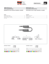
For the plug connection between controller and the device please use the enclosed adapter cable. For this
purpose, connect the DMX input plug of the device with the adapter cable. Fasten the locknuts on the
connectors. Then connect the 3-pin XLR-plugs of the adaper cable with the 3-pin XLR-connectors of the
controller.
To connect one fixture with another, connect the DMX output connector of the first fixture in the DMX chain
to the DMX input plug of the next fixture. Always connect one output with the input of the next fixture until all
fixtures are connected. If required, you can also use the 5 m extension cable (available accessory).
Occupation of the XLR-connection:
If you are using controllers with this occupation, you can connect the DMX-output of the controller directly
with the DMX-input of the first fixture in the DMX-chain. If you wish to connect DMX-controllers with other
XLR-outputs, you need to use adapter cables.
Building a serial DMX-chain:
Connect the DMX-output of the first fixture in the DMX-chain with the DMX-input of the next fixture. Always
connect one output with the input of the next fixture until all fixtures are connected.
Caution: At the last fixture, the DMX-cable has to be terminated with a terminator. Solder a 120
resistor
between Signal (–) and Signal (+) into a 3-pin XLR-plug and plug it in the DMX-output of the last fixture.

00063704.DOC, Version 1.1
20/23
Master/Slave-Operation
The master/slave-operation enables that several devices can be synchronized and controlled by one master-
device.
On the rear panel of the EUROLITE LED IP PAR 36x1W RGB/LED IP PAR 12x3W TCL you can find a DMX
input plug and a DMX output connector, which can be used for interconnecting several devices.
Choose the device which is to control the effects. Set the desired Master-mode on the master-device. This
device then works as master-device and controls all other slave-devices, which are to be connected to the
master-device via a balanced microphone lead. Connect the DMX out connectors with the DMX input plug of
the next device.
S
et the DMX start address 001 on every slave-device.
Connection with the mains
Connect the device to the mains with the enclosed power supply cable.
The occupation of the connection-cables is as follows:
Cable Pin International
Brown Live L
Blue Neutral N
Yellow/Green Earth
The earth has to be connected!
If the device will be directly connected with the local power supply network, a disconnection switch with a
minimum opening of 3 mm at every pole has to be included in the permanent electrical installation.
The device must only be connected with an electric installation carried out in compliance with the IEC-
standards. The electric installation must be equipped with a Residual Current Device (RCD) with a maximum
fault current of 30 mA.
Lighting effects must not be connected to dimming-packs.
OPERATION
After you connected the spot to the mains, the EUROLITE LED IP PAR 36x1W RGB/LED IP PAR 12x3W
TCL starts running.
The LED display lights up and you can choose the desired mode via the buttons MODE, ENTER, UP and
DOWN.
Attention: After every 8 LED IP PAR 36x1W RGB/LED IP PAR 12x3W TCL, the fixtures must have a
renewed connection with the power mains.
Please make sure that open contacts are closed with the enclosed caps in order to avoid humidity
and dirt in the device.
The device has two operating modes. It can be operated in Stand Alone or in DMX-controlled mode.
- STAND ALONE-MODE
Setting Solid Colors
Setting LED Colors (0 – 100%)
Internal Programs
- DMX MODE

00063704.DOC, Version 1.1
21/23
Stand Alone-Mode
In the Stand Alone mode, the LED IP PAR 36x1W RGB/LED IP PAR 12x3W TCL can be used without
controller.
D
isconnect the LED IP PAR 36x1W RGB/LED IP PAR 12x3W TCL from the controller.
Control Board
T
he Control Board offers several features: you can simply set the starting address or run the internal
programs.
Browse through the main menu by pressing MODE. You can change the selection by pressing Up or Down.
Confirm every selection by pressing the Enter-button. The functions provided are described in the following
sections. You can leave every mode by pressing the MODE-button.
Setting the DMX Start Address:
Mode: Value:
Addr
1 - 512
Setting DMX Mode
Mode: Value:
05CH (default setting)
CH
03CH
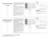
Setting solid colors:
When the display shows C, you can select the desired solid color. Please see the following table.
Mode: Value: Function:
C01 Red
C02 Yellow
C03 Green
C04 Cyan
C05 Blue
C06 Magenta
C
C07 White
Setting internal programs:
When the display shows P, you can select the desired internal program. Please see following table.
Mode: Value: Function:
P01
Endless loop in 7 colors,
change every 3 seconds
P02
Endless loop in 7 colors,
fade every 3 seconds
P03
Endless loop in 3 colors,
change every 3 seconds
P
P04
Endless loop in 3 colors,
fade every 3 seconds
Setting LED colors (0 – 100%):
You can select the dimmer itensity of the LED colors (from 0 to 100 % [1-255]).
Please see the following table.
Mode: Value: Function:
r
1 - 255 Red (0-100%)
G
1 - 255 Green (0-100%)
b
1 - 255 Blue (0-100%)

00063704.DOC, Version 1.1
22/23
DMX-Mode
The device has 2 DMX-modes. The Control Board allows you, as described above, to assign the DMX-Mode.
Addressing
Press the MODE-button until the display shows Addr. You can now set the desired address via the UP or
D
OWN buttons. Press Enter to confirm. The Control Board allows you to assign the DMX fixture address,
which is defined as the first channel from which the LED IP PAR 36x1W RGB/LED IP PAR 12x3W TCL will
respond to the controller.
Please, be sure that you don’t have any overlapping channels in order to control each LED IP PAR 36x1W
RGB/LED IP PAR 12x3W TCL correctly and independently from any other fixture on the DMX-chain.
I
f several LED IP PAR 36x1W RGB/LED IP PAR 12x3W TCL are addressed similarly, they will work
synchronically.
Controlling:
After having addressed the LED IP PAR 36x1W RGB/LED IP PAR 12x3W TCL, you may now start operating
it via your lighting controller.
Note:
It’s necessary to insert the XLR termination plug with 120
in the last lighting in the link in order to ensure
proper transmission on the DMX data link.
DMX-Protocol
5 Channel Mode
Channel: Value: Function:
1 000 – 255 Red (0 – 100%)
Channel: Value: Function:
2 000 – 255 Green (0 – 100%)
Channel: Value: Function:
3 000 – 255 Blue (0 – 100%)
Channel: Value: Function:
4 000 – 255 Dimmer (0 – 100%)
Channel: Value: Function:
000 – 000 ON
001 – 005 No function
006 – 010 ON
5
011 – 255 Strobe (increasing)
3 Channel Mode
Channel: Value: Function:
1 000 – 255 Red (0 – 100%)
Channel: Value: Function:
2 000 – 255 Green (0 – 100%)
Channel: Value: Function:
3 000 – 255 Blue (0 – 100%)

00063704.DOC, Version 1.1
23/23
CLEANING AND MAINTENANCE
The operator has to make sure that safety-relating and machine-technical installations are inspected by an
expert after every four years in the course of an acceptance test.
The operator has to make sure that safety-relating and machine-technical installations are inspected by a
skilled person once a year.
The following points have to be considered during the inspection:
1) All screws used for installing the devices or parts of the device have to be tightly connected and must not
be corroded.
2) There must not be any deformations on housings, fixations and installation spots (ceiling, suspension,
trussing).
3) The electric power supply cables must not show any damages, material fatigue (e.g. porous cables) or
sediments. Further instructions depending on the installation spot and usage have to be adhered by a
skilled installer and any safety problems have to be removed.
Disconnectfrommainsbeforestartingmaintenanceoperation!
DANGERTOLIFE!
We recommend a frequent cleaning of the device. Please use a soft lint-free and moistened cloth. Never use
alcohol or solvents!
There are no serviceable parts inside the device. Maintenance and service operations are only to be carried
out by authorized dealers.
Should you need any spare parts, please use genuine parts.
If the power supply cable of this device becomes damaged, it has to be replaced by authorized dealers only
in order to avoid hazards.
Should you have further questions, please contact your dealer.
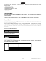
TECHNICAL SPECIFICATIONS
LED IP PAR 36x1W RGB LED IP PAR 12x3W TCL
Power supply: 230 V AC, 50 Hz ~ 230 V AC, 50 Hz ~
Power consumption: 50 W/90 VA 50 W/90 VA
Number of DMX channels: 3/5 3/5
DMX connection: 3-pin screw connector 3-pin screw connector
Protection grade: IP 65 IP 65
Number of LEDs: 36 12
Type of LEDs: 1 W 3 W, TCL
Beam angle: 15° 25°
Dimensions (LxWxH): 200 x 240 x 320 mm 200 x 240 x 320 mm
Weight: 3.75 kg 3.75 kg
Maximum ambient temperature T
a
: 45° C 45° C
Maximum housing temperature T
C
: 60° C 60° C
Min. distance from flammable surfaces: 0.5 m 0.5 m
Min. distance to lighted object: 0.1 m 0.1 m
Accessory:
230V cable for LED-Par IP65, 5m No. 51914197 No. 51914197
Please note: Every information is subject to change without prior notice. 17.09.2012 ©
-
 1
1
-
 2
2
-
 3
3
-
 4
4
-
 5
5
-
 6
6
-
 7
7
-
 8
8
-
 9
9
-
 10
10
-
 11
11
-
 12
12
-
 13
13
-
 14
14
-
 15
15
-
 16
16
-
 17
17
-
 18
18
-
 19
19
-
 20
20
-
 21
21
-
 22
22
-
 23
23


EuroLite LED IP PAR 12x3W TCL User manual
- Category
- Stroboscopes & disco lights
- Type
- User manual
- This manual is also suitable for
Ask a question and I''ll find the answer in the document
Finding information in a document is now easier with AI
in other languages
Related papers
-
EuroLite AC-300 DMX LED User manual
-
-
-
-
-
-
-
-
-
Other documents
-
SHOWTEC LED Bar DMX User manual
-
Contest LED-UV12 User manual
-
 ESS TCL-8-W Installation guide
-
 ESS TCL-6 Installation guide
-
Genius RMG1 RMG2 Operating instructions
-
Rutenbeck 23510302 - PP-24/1 PoE User manual
-
Viessmann LED Luminaire User manual
-
 Multi-Contact M-0HD-GG Installation guide
-
 B-right Path Lights Outdoor, 6 Pcs LED Pathway Lights Acrylic Bubble 12V Low Voltage Landscape Lighting Plug in Extendable Waterproof Garden Lights 360 Lumens for Patio, Yard, Lawn, 2700K User manual
-
 ECOWHO Landscape Lighting, Low Voltage Landscape Lights, 6-in-1 LED Patio Garden Lights for Outdoor Pathway Driveway Wall Tree Yard (12v, Warm White) User guide


