Best UP26M30SB UP26M Installation Manual SV21517 rev. 03
- Category
- Cooker hoods
- Type
- UP26M Installation Manual SV21517 rev. 03

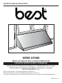
UP26M SERIES
HB0029
INSTALLATION INSTRUCTIONS
INTENDED FOR DOMESTIC COOKING ONLY
INSTALLER: LEAVE THIS MANUAL WITH HOMEOWNER.
HOMEOWNER: USE AND CARE INFORMATION ON PAGES 13 AND 14.
READ AND SAVE THESE INSTRUCTIONS
BEST; Hartford, Wisconsin www.BestRangeHoods.com 800-558-1711
BEST; Drummondville, QC, Canada www.BestRangeHoods.com 866-737-7770
To register your product online or for additional information visit www.BestRangeHoods.com
SV21517 rev. 03
! !

2
TO REDUCE THE RISK OF FIRE, ELECTRIC SHOCK OR
INJURY TO PERSONS, OBSERVE THE FOLLOWING:
1. Use this unit only in the manner intended by the manufacturer.
If you have questions, contact the manufacturer at the address
or telephone number listed in the warranty.
2. Before servicing or cleaning unit, switch power off at service
panel and lock service disconnecting means to prevent
power from being switched on accidentally. When the service
disconnecting means cannot be locked, securely fasten a
prominent warning device, such as a tag, to the service panel.
3. Installation work and electrical wiring must be done by
qualified personnel in accordance with all applicable codes
and standards, including fire-rated construction codes and
standards.
4. Sufficient air is needed for proper combustion and exhausting
of gases through the flue (chimney) of fuel burning equipment
to prevent backdrafting. Follow the heating equipment
manufacturer’s guidelines and safety standards such as
those published by the National Fire Protection Association
(NFPA) and the American Society for Heating, Refrigeration
and Air Conditioning Engineers (ASHRAE) and the local code
authorities.
5. When cutting or drilling into wall or ceiling, do not damage
electrical wiring and other hidden utilities.
6. Ducted fans must always be vented to the outdoors.
7. Do not use this unit with any additional solid-state speed
control device.
8. To reduce the risk of fire, use only metal ductwork.
9. This unit must be grounded.
10. When applicable local regulations comprise more
restrictive installation and/or certification requirements,
the aforementioned requirements prevail on those of this
document and the installer agrees to conform to these at his
own expenses.
TO REDUCE THE RISK OF A RANGE TOP GREASE FIRE:
a) Never leave surface units unattended at high settings. Boilovers
cause smoking and greasy spillovers that may ignite. Heat oils
slowly on low or medium settings.
b) Always turn hood ON when cooking at high heat or when
flambeing food (i.e.: Crêpes Suzette, Cherries Jubilee,
Peppercorn Beef Flambé).
c) Clean ventilating fans frequently. Grease should not be allowed
to accumulate on fan, filters or in exhaust ducts.
d) Use proper pan size. Always use cookware appropriate for the
size of the surface element.
1. For indoor use only.
2. For general ventilating use only. Do not use to exhaust
hazardous or explosive materials and vapors.
3. To avoid motor bearing damage and noisy and/or unbalanced
impeller, keep drywall spray, construction dust, etc. off power
unit.
4. Your hood motor has a thermal overload which will
automatically shut off the motor if it becomes overheated. The
motor will restart when it cools down. If the motor continues to
shut off and restart, have the hood serviced.
5. For best capture of cooking impurities, the bottom of the hood
should be at a minimum of 24” and at a maximum of 36” above
the cooking surface.
6. Two installers are recommended because of the large size and
weight of this unit.
7. To reduce the risk of fire and to properly exhaust air, be sure to
duct air outside — Do not exhaust air into spaces within walls
or ceiling or into attics, crawl space or garage.
8. This product is equipped with a thermostat which may start
blower automatically. To reduce the risk of injury and to prevent
power from being switched on accidentally, switch power off at
service panel and lock or tag service panel.
9. Because of the high exhausting capacity of this unit, you
should make sure enough air is entering the house to replace
exhausted air by opening a window close to or in the kitchen.
10. To reduce the risk of fire and electric shock, the Best UP26M
Series hood must be installed with Best interior blower model
iQ6, P3, P5, P6 or P8; Best exterior models EB6, EB9, EB12
or EB15; Best in-line blowers models ILB3, ILB6, ILB9 or
ILB11. Other blowers cannot be substituted. (Blowers sold
separately.)
11. Please read specification label on product for further
information and requirements.
WARNING
!
CAUTION
TO REDUCE THE RISK OF INJURY TO PERSONS IN THE
EVENT OF A RANGE TOP GREASE FIRE, OBSERVE
THE FOLLOWING*:
1. SMOTHER FLAMES with a close-fitting lid, cookie sheet or
metal tray, then turn off the burner. BE CAREFUL TO PREVENT
BURNS. IF THE FLAMES DO NOT GO OUT IMMEDIATELY,
EVACUATE AND CALL THE FIRE DEPARTMENT.
2. NEVER PICK UP A FLAMING PAN — You may be burned.
3. DO NOT USE WATER, including wet dishcloths or towels —
This could cause a violent steam explosion.
4. Use an extinguisher ONLY if:
A. You own a Class ABC extinguisher and you know how to
operate it.
B. The fire is small and contained in the area where it started.
C. The fire department has been called.
D. You can fight the fire with your back to an exit.
* Based on “Kitchen Fire Safety Tips” published by NFPA.
WARNING
!

3
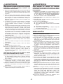
HL0220
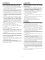
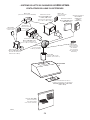
- UP26M SERIES RANGE HOOD SYSTEM -
INTERIOR BLOWERS
MODEL 647
(7” ROUND WALL CAP)
MODEL 634 OR 644
(ROOF CAP)
8” R
OUND
STANDARD
DUCT
MODEL 413
TRANSITION
(3¼” X 10” TO 8”)
M
ODEL 459 TRANSITION
(3¼” X 14” TO 8”)
M
ODEL 643
(8” ROUND WALL CAP)
A
DAPTER/DAMPER
3¼” X 14”
(SUPPLIED WITH P8 BLOWER)
UP26M HOOD
MODEL 412
TRANSITION
(3¼” X 10” TO 7”)
M
ODEL 407
(7” ROUND—
2 FT SECTIONS)
M
ODEL 415
7” ROUND
ADJUSTABLE
ELBOW
(OPTIONAL)
8” ROUND ADJUSTABLE
ELBOW (OPTIONAL)
STANDARD
3¼” X 14” DUCT
FLOW DEVIATOR
(VERTICAL EXHAUST ONLY)
(SUPPLIED WITH P5 AND P8 BLOWERS)
A
DAPTER/DAMPER 3¼” X 10”
(SUPPLIED WITH P5 AND P8
BLOWERS)
R
OUGH-IN KIT
(SUPPLIED WITH P5 AND P8 BLOWERS)
MODEL P5
SINGLE-BLOWER (500 CFM)
BACKSPLASH (RMP SERIES)
(STAINLESS STEEL WALL COVERING
WITH WARMING SHELVES. OPTIONAL)
M
ODEL P8 DUAL-BLOWER (900 CFM)
FOR USE WITH 36” HOODS OR WIDER
NOTE: The dual blower P8 must
be installed with 3¼” x 14”
duct. If it is impossible to
connect the dual blower P8
to a 3¼” x 14” duct, use a
3¼” x 10” duct. In that case,
the blower performance will
be decreased by 25%.
STANDARD
3¼” X 10”
DUCT
MODEL 634 OR 644
(ROOF CAP)
UP26M HOOD
MODEL 438
8” ROUND ADAPTER/DAMPER
(SUPPLIED WITH P3, P6 AND
IQ6 BLOWERS)
ROUGH-IN KIT
(SUPPLIED WITH P3, P6 AND IQ6 BLOWERS)
MODELS P3 (300 CFM), P6 (600 CFM)
OR IQ6 (600 CFM) SINGLE BLOWER
MODEL 643
(8” ROUND WALL CAP)
MODEL 408
8” ROUND
STANDARD DUCT
MODEL 432
8” ROUND ADJUSTABLE
ELBOW (OPTIONAL)

4
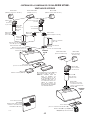
HL0071
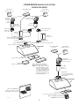
- UP26M SERIES RANGE HOOD SYSTEM -
IN-LINE AND EXTERIOR BLOWERS
MODEL 441
(10” R
OUND WALL CAP)
M
ODEL 437
(H
IGH CAPACITY ROOF CAP)
M
ODEL ILB9 (800 CFM)
OR ILB11 (1100 CFM)
IN-LINE BLOWER
(INCLUDES TWO 8” X 12” TO
10’’
ROUND TRANSITIONS)
M
ODEL 418
(10” ROUND
ADJUSTABLE ELBOW)—
OPTIONAL
MODEL 421
(10” ROUND VERT.
IN-LINE DAMPER)
(RECOMMENDED FOR USE
WITH EXTERIOR BLOWERS)
MODEL EB6 (600 CFM)
OR EB9 (900 CFM)
EXTERIOR BLOWER
MODEL EB12 (1200 CFM)
OR EB15 (1500 CFM)
EXTERIOR BLOWER
MODEL 410
(10” ROUND DUCT
—2FT. SECTIONS)
I
N-LINE AND EXTERIOR BLOWER ROUGH-IN KIT
(INCLUDED WITH EB6, EB9, EB12, EB15,
ILB3, ILB6, ILB9 AND ILB11 BLOWERS).
UP26M
HOOD
MODEL ILB3 (280 CFM)
IN-LINE BLOWER
(INCLUDES ONE 8” TO 10”
ROUND TRANSITION)
MODEL ILB6 (600 CFM)
IN-LINE BLOWER
(INCLUDES TWO 4½” X 18½”
TO 10’’ ROUND TRANSITIONS)
MODEL 643
(8” ROUND
WALL
CAP)
RMP SERIES BACKSPLASH
(STAINLESS STEEL WALL
COVERING WITH WARMING
SHELVES. OPTIONAL)
M
ODEL 441
(10” ROUND
WALL CAP)

5
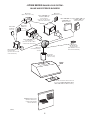
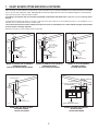
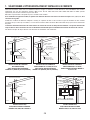
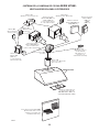
1. SELECT BLOWER OPTION AND INSTALL DUCTWORK
Either an interior or exterior blower or in-line blower may be used with this hood. The Best UP26M must be installed with blower models iQ6,
P3, P5, P6, P8, ILB3, ILB6, ILB9, ILB11, EB6, EB9, EB12 or EB15 only. Other blowers cannot be substituted. (Blowers sold separately).
Plan where and how the ductwork will be installed.
If installing in-line blower, refer to instructions packed with in-line blower and follow steps 1 up to 3, 5, 8, 11, 12, 16 and up of this
manual.
Install proper-sized ductwork, elbow(s) and roof or wall cap for the type of blower you are installing. If using 7” or 8” round ducts, use a
transition. Use 2” metal foil duct tape to seal duct joints.
The minimum hood distance above cooktop must not be less than 24”. A maximum of 36” above cooktop is highly recommended
for best capture of cooking impurities.
Distances over 36” are at the installer and users discretion.
3¼” x 10”
OR 3¼” x 14”
HH0213A
24” TO 36”
ABOVE COOKING SURFACE
ROOF CAP
WALL
CAP
HOOD
7” OR 8”
ROUND DUCT
3¼” X 10” TO 7”
OR 8” TRANSITION
OR 3¼”
X 14” TO 8”
TRANSITION
HH0214A
24” TO 36”
ABOVE COOKING SURFACE
ROOF CAP
WALL
CAP
HOOD
HOOD
10” ROUND DUCT
EXTERIOR BLOWER
HH0217A
EXTERIOR
BLOWER
24” TO 36”
ABOVE COOKING SURFACE
MODEL P5 (SINGLE) OR P8 (DOUBLE)
INTERIOR BLOWER
TYPICAL RECTANGULAR DUCTWORK
MODEL P5 (SINGLE) OR P8 (DOUBLE)
INTERIOR BLOWER
7” OR 8” ROUND DUCTWORK
MODEL EB6, EB9, EB12 OR EB15
EXTERIOR BLOWER
TYPICAL DUCTWORK
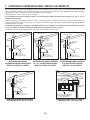
HH0212A
IN-LINE BLOWER
10” ROUND DUCT
(
EXCEPT HLB3, 8’’ ROUND DUCT)
24” TO 36”
ABOVE COOKING SURFACE
ROOF CAP
WALL
CAP
HOOD
MODEL ILB3, ILB6, ILB9 OR ILB11
IN-LINE BLOWER
TYPICAL DUCTWORK
8” ROUND DUCT
HH0215A
24” TO 36”
ABOVE COOKING SURFACE
ROOF CAP
WALL
CAP
HOOD
MODEL P3, P6 or iQ6 (SINGLE)
INTERIOR BLOWER
8” ROUND DUCTWORK

6
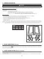
2. PREPARE INSTALLATION
WARNING
!
When performing installation, servicing or cleaning the unit, it is recommended to wear safety glasses and gloves.
NOTE: Before proceeding to the installation, check the contents of the box. If items are missing or damaged, contact the manufacturer.
Make sure that the following items are included:
- Range hood
- Accessories: • Hybrid baffle filters with handles
• Shielded halogen bulbs (120 V, 50 W, MR16 with GU10 base or PAR16 with GU10 base)
• Bag of parts including: 4 lock nuts no. 10-32, 1 wire clamp LP16-AP, 2 no. 6 x 1/2” screws,
2 wire connectors no. 74B, 6 no. 8 x 3/8”, 8 double threaded screws 6-12 x 1/2”
Parts sold separately:
• Interior blower Model P5 or P8 includes blower, rough-in kit, flow deviator and 3¼” x 10” or 3¼” x 14” adapter
• Interior blower Model iQ6, P3 or P6 includes blower, rough-in kit, adapter/damper
• In-line blower assembly ILB3, ILB6, ILB9 or ILB11 (all include transition(s) and rough-in plate)
• Exterior blower assembly EB6, EB9, EB12 or EB15 (all include rough-in plate)
• Backsplash (optional)
• Transitions, duct, elbows, dampers, wall and roof caps. Refer to pages 3 and 4 for a complete list of venting options and model numbers.
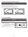
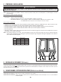
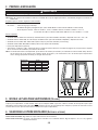
NOTE: For cabinets with recessed bottom, attach wood filler strips (not included) on each sides, as shown below. Use two 2-inch wide
strips for 30” wide hoods, and four 2-inch wide strips for wider hoods, cut to length. See below for wood filler strip locations.
HOOD
WIDTHS
LOCATIONS
ABC
30” 2” N/A N/A
36” 2” 4½” 4½”
42” 2” 7¼” 8¼”
48" 4” 10¼” 11¼”
HD0079
A
A
B C
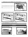
3. INSTALL BACKSPLASH (OPTIONAL)
Backsplash must be installed before the hood shell because the hood shell covers the backsplash top mounting screws. In order to be
able to install the backsplash, ensure to have at least 18” clearance between bottom of hood and range control panel or cooktop. (See
instructions packed with backsplash.)
4. SELECT BLOWER OPTION (EXTERIOR OR INTERIOR)
INTERIOR BLOWER: Follow all subsequent steps of this manual.
EXTERIOR BLOWER: Refer to instructions packed with exterior blower and follow steps 5, 8, 11,12, 16 and up of the present manual.

7
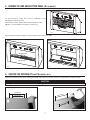
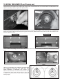
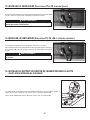
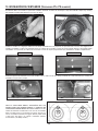
6. CHOOSE THE OPENING (P5 AND P8 BLOWERS ONLY)
Removing horizontal knockout opening on back of hood.
CAUTION
If using P5 blower, remove 10” wide knockout. If using P8 blower, remove either 10” or 14” wide knockout.
Remove the knockout for the chosen opening (horizontal at the back of the hood or vertical on rough-in plate). See pictures below.
14” KNOCKOUT
10” KNOCKOUT
HD0076
14
”
KNOCKOUT
HD0077
10”
KNOCKOUT
Removing vertical knockout opening on rough-in plate.
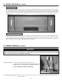
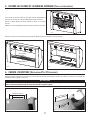
5. REMOVE FILTERS AND BOTTOM PANEL (ALL BLOWERS)
Lay the hood flat on a table. Use a piece of cardboard to avoid
damaging the table or the hood.
Remove tape on filters. Remove filters from hood and set aside.
NOTE: It is recommended to start with the center one(s).
HD0542
HD0541
RETAINING SCREWS
BOTTOM PANEL
Remove bottom panel both retaining screws. Set bottom panel and screws aside.
HD0544
1
3
2

8
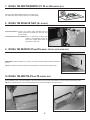
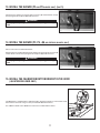
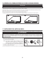
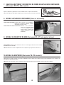
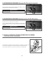
10. INSTALL THE ADAPTER (P5 AND P8 BLOWERS ONLY)
Using provided screws, secure the adapter to the top (or back) of the hood. Seal the adapter to the hood using metal foil duct tape.
NOTE: For vertical exhaust, ensure that the damper pivot is located towards the front of the hood.
HD0005 HD0006
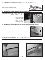
YOU MUST install the deviator if you choose to vent the hood vertically. Install the deviator as
shown.
NOTE: If installed correctly, the deviator will protrude about 1/8” above the rough-in plate.
8. INSTALL THE ROUGH-IN PLATE (ALL BLOWERS)
INTERIOR BLOWER: Secure the rough-in plate (provided with the
blower) inside the hood with four lock nuts. See
picture at right.
EXTERIOR OR IN-LINE BLOWER: Refer to instructions included with
exterior or in-line blower rough-in kit.
Secure the rough-in plate inside the
hood with four lock nuts.
9. INSTALL THE DEVIATOR (P5 AND P8 BLOWERS, VERTICAL INSTALLATION ONLY)
HD0003
Inserting deviator into hood vertical opening.
HD0048
BLOWER PLATE
LOCK NUTS
Attach 8” round adapter/damper to blower rough-in plate.
Use metal duct tape to make all joints secure and air-tight.
7. INSTALL THE ADAPTER/DAMPER (P3, P6 AND IQ6 BLOWERS ONLY)
HO0196

9
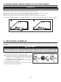
12. CONNECT WIRING (ALL BLOWERS)
WARNING
!
Risk of electric shock. Electrical wiring must be done by qualified personnel in accordance with all applicable
codes and standards. Before connecting wires, switch power off at service panel and lock service disconnecting
means to prevent power to be switched on accidentally.
INTERIOR BLOWER: Connect cable into wiring box using wire connectors.
Connect wires as follow: BLACK to BLACK, WHITE to WHITE and
GREEN or bare wire under ground screw. Reinstall wiring cover.
DO NOT FORGET TO CONNECT THE GROUND.
IN-LINE OR EXTERIOR BLOWER: Remove rough-in plate wiring cover and connect wiring (see instructions included with in-line or
exterior blower).
HE0012
GROUND SCREW
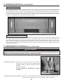
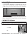
11. INSTALL THE HOOD (ALL BLOWERS)
Run power cable to installation location. Place the hood to its location. Mark the position of the screws (smaller part of the key holes)
with a pen. Remove the hood and install the (8) 1/2” double thread screws leaving a 1/8” gap (4 screws for 30” hood). Remove wiring
cover, place the wire clamp, insert the cable in the hood and tighten the wire clamp to secure the cable. Place the hood under the
cabinet and slide it in position. Make sure the adapter/damper assembly enters the ducting. Secure the hood by tightening the screws
completely.
HD0043
Run power cable to installation location. Place the hood to its location. Mark the position of the screws (smaller part of the key holes)
with a pen. Remove the hood and install the (8) 1/2” double thread screws leaving a 1/8” gap (4 screws for 30” hood). Remove wiring
cover on top of the hood and connect wiring (see instructions included with exterior blower). Place the hood under the cabinet and
slide it in position. Secure the hood by tightening the screws completely.
INTERIOR BLOWER
IN-LINE OR EXTERIOR BLOWER

10
Install screws into the location as shown in the pictures below (P5 or P8 blower). Do not tighten screws down fully, leave a 1/8” gap. Hang
blower unit onto blower plate (screws through the large part of the keyhole). Slide the blower to its position (screws in the small part of the
keyhole). Tighten the screws.
HD0044
Secure the blower by installing 2 more screws into the locations shown in the pictures below (P5 or P8 blower). Reinstall impeller(s) and
cover.
HD0080
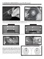
13. INSTALL THE BLOWER (P5 AND P8 BLOWERS ONLY)
The blower must be installed to the rough-in plate using four 3/8” screws. Remove the cover from the blower assembly. Remove the
impeller(s) by pulling it (them) out gently (see pictures below).
HD0021
HD0022
P5 BLOWER
HD0081
P8 BLOWER
HD0045
FOR P8 DUAL BLOWER UNIT, ENSURE THE IMPELLERS
ARE CORRECTLY INSTALLED; THE HOOD WILL NOT
WORK PROPERLY IF REVERSED. Both impellers are
different in the dual blower, one rotates clockwise and the other
counterclockwise. Each wheel and motor have an arrow and
a number on them, you have to match them correctly (see
drawing at right).
21
HD0023
FRONT
1
2
HD0023

11
14. INSTALL THE BLOWER (P3, P6, IQ6 AND EXTERIOR BLOWERS ONLY)
Refer to instructions included with blower.
Once the blower is installed, plug the power supply to the 3-prong male connector (A)
and the blower unit into the 2-prong female receptacle (B) inside the hood.
13. INSTALL THE BLOWER (P5 AND P8 BLOWERS ONLY) (CONT'D)
WARNING
!
Never plug the 2-prong blower cord to the 3-prong power supply
cord.
Plug the power supply to the 3-prong male connector (A) and the blower unit into
the 2-prong female receptacle (B) inside the hood.
HE0003
A
B
HE0003
A
B
WARNING
!
Never plug the 2-prong blower cord to the 3-prong power supply
cord.
15. INSTALL THE CALIBRATION BUTTON BRACKET IN THE HOOD
(iQ6 INTERIOR BLOWER ONLY)
The iQ6 blower is equipped with a calibration button already mounted to its own bracket. Install
this bracket in the hood, using 2 screws provided with iQ6 interior blower.
See additional details in the iQ6 blower instructions included with the blower.
HD0007

12
16. REINSTALL BOTTOM PANEL AND HYBRID BAFFLE FILTERS
Reinstall bottom panel using both retaining screws removed in step 5.
Reinstall filters. It is recommended to install side filters first and finish with center one(s).
Insert the end with filter spring clip of hybrid baffle filter into the upper channel of the hood.
Raise the other end toward the inside and insert in the grease drip rail of the hood.
Replacement filters are available from your dealer. See label inside hood for part number.
CAUTION
Remove protective plastic film covering filters before installing them.
1
HD0543
2
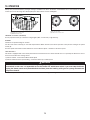
17. LIGHT BULBS REPLACEMENT
This hood requires 120 V, 50 W, MR16 with GU10 base or PAR16 with GU10 base, shielded halogen lamps (included).
1. To remove lamps, gently push upwards and turn counterclockwise to
disengage bulb leads from their grooves.
NOTE: To ease removal of the bulbs, use a rubber dishwashing
glove or use suction cup tool available from Best. Contact
Best Customer Service at 1-800-558-1711 to order suction
cup tool, part no. 99526707.
2. Install the new lamps by placing the bulb leads into their grooves in
the socket.
3. Gently push upwards and turn clockwise until secure.
WARNING
!
Do not touch lamps during or soon after operation. Burns may occur. In order to prevent the risk of personal injury,
only install shielded halogen lamps. Also, never install a cool beam, a dichroïc lamp, a lamp not suitable for use in
recessed luminaires or identified for use in enclosed fixtures.
12 3
HO0089

13
18. USE AND CARE
Hybrid baffle filters and impeller(s)*
The hybrid baffle filters, impeller(s) and grease rail should be cleaned frequently. Use a warm detergent solution. Wash more often if your
cooking style generates greater grease — like frying foods or wok cooking.
Remove filters by pushing filters towards the front of hood and rotating filters downward. Hybrid baffle filters and impeller(s) are dishwasher
safe.
Clean all-metal filters in the dishwasher using a non-phosphate detergent. Discoloration of the filter may occur if using phosphate detergent
or as a result of local water conditions — but this will not affect filter performance. This discoloration is not covered by the warranty.
* Impeller(s) only on P5 and P8 blowers.
Hood cleaning
Stainless steel cleaning:
Avoid when choosing a detergent:
- Any cleaners that contain bleach will attack stainless steel.
- Any products containing: chloride, fluoride, iodide, bromide will deteriorate surfaces rapidly.
- Any combustible products used for cleaning such as acetone, alcohol, ether, benzol, etc., are highly explosive and should never be
used close to a range.
Do:
• Regularly wash with clean cloth or rag soaked with warm water
and mild soap or liquid dish detergent.
• Always clean in the direction of original polish lines.
• Always rinse well with clear water (2 or 3 times) after cleaning.
Wipe dry completely.
• You may also use a specialized household stainless steel
cleaner.
Don’t:
• Use any steel or stainless steel wool or any other scrapers to
remove stubborn dirt.
• Use any harsh or abrasive cleansers.
• Allow dirt to accumulate.
• Let plaster dust or any other construction residues reach the
hood. During construction/renovation, cover the hood to make
sure no dust sticks to stainless steel surface.

14
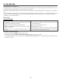
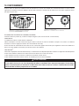
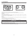
19. OPERATION
HEAT SENTRY™
This hood is equipped with a Heat Sentry™ thermostat. This thermostat is a device that will turn on or speed up the blower if it senses
excessive heat above the cooking surface.
1) If blower is OFF - it turns blower ON to HIGH speed.
2) If blower is ON at a lower speed setting – it turns the blower up to HIGH speed.
When the temperature level drops to normal, the blower will return to its original setting.
WARNING
!
The HEAT SENTRY can start the blower during a range top fire or other excessive heat situations even if the hood
is turned off. In this case, it is impossible to turn the blower OFF with blower switch. If you must stop the blower,
unplug the blower power cord (located behind the filters) from the hood by pulling on its 2-prong connector; do
not pull on the wire.
Always turn your hood on before you begin cooking to establish an air flow in the kitchen. Let the blower run for a few minutes to clear the
air after you turn off the range. This will help keep the whole kitchen cleaner and brighter.
HC0038
1
2
3
HC0039
AB
1) HALOGEN LIGHT KNOB
2) BLOWER SPEED CONTROL KNOB
3) ON/OFF BLOWER SWITCH
1) HALOGEN LIGHT KNOB
2) BLOWER SPEED CONTROL KNOB
COOKTOP LIGHTING (HALOGEN)
A rotary 3-position knob (1) controls the halogen lights (OFF - low intensity - high intensity).
BLOWER
The blower is operated using two controls.
Use the on/off rocker switch (3) to start and stop the blower. When turned on, the blower operates at the previous setting of the speed
control (2).
Turn the speed control knob counterclockwise to increase blower speed – clockwise to decrease speed.

15
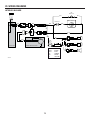
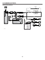
20. WIRING DIAGRAMS
INTERIOR BLOWER
120 VAC
GROUND
LINE
NEUTRAL
BLK
G
W
BLK
W
W
BLK
BLK
W
M
INTERNAL BLOWER ASSEMBLY
ROUGH-IN PLATE
W
BLK
BLK
W
BLK
BLU BLU
HS
T
HERMOSTAT
FAN SWITCH
BLK
S
PEED CONTROL
LAMP
SWITCH
Y
W
Y
LAMP
LAMP
LAMP
W
Y
HE0187A
COLOR CODE
BLK BLACK
BLU BLUE
G GREEN
W WHITE
Y YELLOW

16
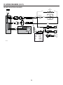
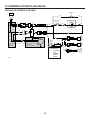
20. WIRING DIAGRAMS (CONT'D)
IN-LINE OR EXTERIOR BLOWER
120 VAC
M
REMOTE BLOWER ASSEMBLY
BLU BLU
HE0188A
G
GROUND
LINE
NEUTRAL
COLOR CODE
BLK BLACK
BLU BLUE
G GREEN
W WHITE
Y YELLOW
BLK
G
W
BLK
W
W
BLK
BLK
W
R
OUGH-IN PLATE
W
BLK
BLK
W
BLK
HS
T
HERMOSTAT
FAN SWITCH
BLK
S
PEED CONTROL
LAMP
SWITCH
Y
W
Y
W
Y
BLK
W
LAMPLAMP
LAMP

17
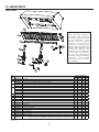
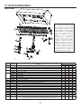
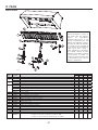
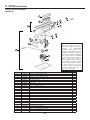
21. SERVICE PARTS
Model UP26M
HL0221
2
10
1
3
4
5
6
7
8
9
11
12
13
14
15
REPLACEMENT PARTS AND REPAIRS
In order to ensure your unit remains in
good working condition, you must use
Broan-NuTone genuine replacement
parts only. Broan-NuTone genuine
replacement parts are specially
designed for each unit and are
manufactured to comply with all the
applicable certification standards and
maintain a high standard of safety.
Any third party replacement part
used may cause serious damage and
drastically reduce the performance
level of your unit, which will result
in premature failing. Broan-NuTone
recommends to contact a certified
service depot for all replacement
parts and repairs.
KEY
NO.
PART NO.DESCRIPTION
QTY. (HOOD WIDTH)
30" 36" 42" 48"
1 SV05869 BEST LOGO 1111
2
SV61639 HYBRID BAFFLE FILTER 8.84" X 8.61" (INCLUDING HANDLE)-31-
SV61640 HYBRID BAFFLE FILTER 11.84" X 8.61" (INCLUDING HANDLE) 2-23
3
SV61691 F
ILTER FILLER 1.6" (PAIR)-11-
SV61679 FILTER FILLER 3" (PAIR) ---1
4
SV61742 GREASE RAIL 30" 1---
SV61743 G
REASE RAIL 36" -1--
SV61744 G
REASE RAIL 42" --1-
SV61745 GREASE RAIL 48" ---1
5 SV05917 S
OCKET GU10 2233
6 SV09435 S
OCKET HOLDER GU10 2233
7 SV09434 LIGHT TRIM, STAINLESS STEEL 2233
8 SV05921 SHIELDED HALOGEN BULBS (50 W, 120 V, PAR16, GU10) 2233
9 SV08578 B
LOWER AND LIGHT KNOBS (2 KNOBS) 1111
10 SV03435 THERMOSTAT 1111
11 SV08338 LIGHT SWITCH 1111
12 SV03501 SPEED CONTROL 1111
13 SV08548 BLOWER ROCKER SWITCH 1111
14 SV13923 FEMALE CONNECTOR 1111
15 SV13924 MALE CONNECTOR 1111
* SV17645 THERMOSTAT BRACKET 1111
* SV21517 INSTALLATION GUIDE 1111
* SV13278
PARTS BAG: 4 LOCK NUTS NO. 10-32, 1 WIRE CLAMP LP16-AP, 2 NO. 6 X 1/2” SCREWS,
2 WIRE CONNECTORS NO. 74B, 6 NO. 8 X 3/8”, 8 DOUBLE THREADED SCREWS 6-12 X 1/2”
1111
* NOT SHOWN.

18
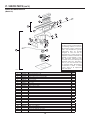
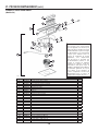
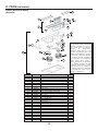
21. SERVICE PARTS (CONT'D)
5
1
2
3
4
5
6
7
8
9
10
11
12
6
13
14
15
16
17
18
19
20
21
22
23
HL0021
REPLACEMENT PARTS AND REPAIRS
In order to ensure your unit remains in
good working condition, you must use
Broan-NuTone genuine replacement
parts only. Broan-NuTone genuine
replacement parts are specially
designed for each unit and are
manufactured to comply with all the
applicable certification standards and
maintain a high standard of safety.
Any third party replacement part
used may cause serious damage and
drastically reduce the performance
level of your unit, which will result
in premature failing. Broan-NuTone
recommends to contact a certified
service depot for all replacement
parts and repairs.
KEY NO.PART NO.DESCRIPTION QTY.
1 SV13296 ADAPTER/DAMPER 3¼” X 10” 1
2 SV03500 AIR DEFLECTOR 1
3 SV12997 SINGLE BLOWER ROUGH-IN PLATE ASSEMBLY 1
4 SV03577 FOAM 1/2” X 1/2” X 12” 1
5 SV02160 CAPACITOR 15 µF 1
6*M
ACHINE SCREW NO. 6-32 X 1/4” 4
7 SV01857 WIRE COVER 1
8*LOCK NUT NO. 6-32 1
9 SV14973 SINGLE BLOWER ASSEMBLY 1
10 SV01810 IMPELLER RING 1
11 SV03400 BLOWER IMPELLER 7.094” X 3.375” CW 1
12 SV01766 MOTOR 165 W CW 1
13 * WASHER 3/16” ID X 3/4” OD 3
14 SV02001 MOTOR GROMMET G-431-1 3
*8” TIE WRAP 2
15 SV11705 M
OTOR MOUNT 1
*W
IRE NO. 18 TEW BROWN X 10” 1
16 SV01927 METRIC SCREW M4 X 6 MM PA N QUADREX 4
17 SV03495 STRAIN RELIEF FOR BLOWER POWER CORD 1
18 SV03494 36” BLOWER POWER CORD 1
19 SV13230 OUTLET BOX COVER 1
20 SV03496 POWER CORD, 120 VOLTS 1
21 SV00660 STRAIN RELIEF FOR POWER CORD 1
22 * SCREW NO. 8 X 3/8”, T/B, NO. 8 HEAD 2
23 * SCREW NO. 10-32 X 3/8”, TF, GREEN 2
* STANDARD HARDWARE—MAY BE PURCHASED LOCALLY.
SINGLE BLOWER/ROUGH-IN
(Model P5)

19
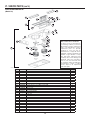
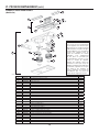
21. SERVICE PARTS (CONT'D)
1
3
4
5
2
6
7
8
9
10
12
11
HL0022
13
14
18
17
15
16
19
20
22
23
24
25
21
REPLACEMENT PARTS AND REPAIRS
In order to ensure your unit remains in
good working condition, you must use
Broan-NuTone genuine replacement
parts only. Broan-NuTone genuine
replacement parts are specially
designed for each unit and are
manufactured to comply with all the
applicable certification standards and
maintain a high standard of safety.
Any third party replacement part
used may cause serious damage and
drastically reduce the performance
level of your unit, which will result
in premature failing. Broan-NuTone
recommends to contact a certified
service depot for all replacement
parts and repairs.
KEY NO.PART NO.DESCRIPTION QTY.
1 SV14971 ADAPTER/DAMPER 3¼” X 14” 1
2 SV13296 A
DAPTER/DAMPER 3¼” X 10” 1
3 SV03500 AIR DEFLECTOR 1
4 SV14975 DUAL BLOWER ROUGH-IN PLATE ASSEMBLY 1
5 SV03577 FOAM 1/2” X 1/2” X 12” 1
6*L
OCK NUT NO. 6-32 1
7 SV02160 C
APACITOR 15 µF 2
8 SV01857 WIRE COVER 2
9 SV01766 MOTOR 165 W CW 1
10 SV03400 BLOWER IMPELLER, HOOD 7.094” X 3.375” CW 1
11 SV14974 DUAL BLOWER ASSEMBLY 1
12 SV01810 I
MPELLER RING 2
13 SV03399 BLOWER IMPELLER, HOOD 7.094” X 3.375” CCW 1
14 SV03457 MOTOR 165 W CCW 1
15 * WASHER 3/16” ID X 3/4” OD 6
*8” T
IE WRAP 4
16 SV11705 M
OTOR MOUNT 2
*WIRE NO. 18 TEW BROWN X 10” 2
17 SV02001 MOTOR GROMMET G-431-1 6
18 SV01927 METRIC SCREW SCREW M4 X 6 MM PA N QUADREX 8
19 SV03495 STRAIN RELIEF FOR BLOWER CORD 1
20 SV03494 36” B
LOWER POWER CORD 1
21 SV14960 OUTLET BOX COVER 1
22 SV03496 POWER CORD, 120 VOLTS 1
23 SV00660 STRAIN RELIEF FOR POWER CORD 1
24 * SCREW NO. 8 X 3/8”, T/B, NO. 8 HEAD 4
25 * SCREW NO. 10-32 X 3/8”, TF, GREEN 2
* STANDARD HARDWARE—MAY BE PURCHASED LOCALLY.
DUAL BLOWER/ROUGH-IN
(Model P8)

20
22. WARRANTY
ONE-YEAR LIMITED WARRANTY
Broan-NuTone LLC (Broan-NuTone) warrants to the original consumer purchaser of Best products that such products will be free
from defects in materials or workmanship for a period of one year from the date of original purchase. THERE ARE NO OTHER
WARRANTIES, EXPRESS OR IMPLIED, INCLUDING, BUT NOT LIMITED TO, IMPLIED WARRANTIES OR MERCHANT ABILITY OR
FITNESS FOR A PARTICULAR PURPOSE.
During this one-year period, Broan-NuTone will, at its option, repair or replace, without charge, any product or part which is found to be
defective under normal use and service.
THIS WARRANTY DOES NOT EXTEND TO FLUORESCENT LAMP STARTERS, TUBES, HALOGEN AND INCANDESCENT BULBS,
FUSES, FILTERS, DUCTS, ROOF CAPS, WALL CAPS AND OTHER ACCESSORIES FOR DUCTING. This warranty does not cover
(a) normal maintenance and service or (b) any products or parts which have been subject to misuse, negligence, accident, improper
maintenance or repair (other than by Broan-NuTone), faulty installation or installation contrary to recommended installation instructions.
The duration of any implied warranty is limited to the one-year period as specified for the express warranty. Some states or provinces
do not allow limitation on how long an implied warranty lasts, so the above limitation may not apply to you.
BROAN-NUTONE’S OBLIGATION TO REPAIR OR REPLACE, AT BROAN-NUTONE’S OPTION, SHALL BE THE PURCHASER’S
SOLE AND EXCLUSIVE REMEDY UNDER THIS WARRANTY. BROAN-NUTONE SHALL NOT BE LIABLE FOR INCIDENTAL,
CONSEQUENTIAL OR SPECIAL DAMAGES ARISING OUT OF OR IN CONNECTION WITH PRODUCT USE OR PERFORMANCE.
Some states or provinces do not allow the exclusion or limitation of incidental or consequential damages, so the above
limitation or exclusion may not apply to you.
This warranty gives you specific legal rights, and you may also have other rights, which vary from state to state or province to another.
This warranty supersedes all prior warranties.
To qualify for warranty service, you must (a) notify Broan-NuTone at the address or telephone number stated below, (b) give the model
number and part identification and (c) describe the nature of any defect in the product or part. At the time of requesting warranty service,
you must present evidence of the original purchase date.
In USA - Best
®
, 926 W. State Street, Hartford, WI 53027 (800-558-1711)
In Canada - Best
®
, 550 Lemire Blvd., Drummondville, QC, Canada, J2C 7W9 (866-737-7770)
www.BestRangeHoods.com
Page is loading ...
Page is loading ...
Page is loading ...
Page is loading ...
Page is loading ...
Page is loading ...
Page is loading ...
Page is loading ...
Page is loading ...
Page is loading ...
Page is loading ...
Page is loading ...
Page is loading ...
Page is loading ...
Page is loading ...
Page is loading ...
Page is loading ...
Page is loading ...
Page is loading ...
Page is loading ...
Page is loading ...
Page is loading ...
Page is loading ...
Page is loading ...
Page is loading ...
Page is loading ...
Page is loading ...
Page is loading ...
Page is loading ...
Page is loading ...
Page is loading ...
Page is loading ...
Page is loading ...
Page is loading ...
Page is loading ...
Page is loading ...
Page is loading ...
Page is loading ...
Page is loading ...
Page is loading ...
-
 1
1
-
 2
2
-
 3
3
-
 4
4
-
 5
5
-
 6
6
-
 7
7
-
 8
8
-
 9
9
-
 10
10
-
 11
11
-
 12
12
-
 13
13
-
 14
14
-
 15
15
-
 16
16
-
 17
17
-
 18
18
-
 19
19
-
 20
20
-
 21
21
-
 22
22
-
 23
23
-
 24
24
-
 25
25
-
 26
26
-
 27
27
-
 28
28
-
 29
29
-
 30
30
-
 31
31
-
 32
32
-
 33
33
-
 34
34
-
 35
35
-
 36
36
-
 37
37
-
 38
38
-
 39
39
-
 40
40
-
 41
41
-
 42
42
-
 43
43
-
 44
44
-
 45
45
-
 46
46
-
 47
47
-
 48
48
-
 49
49
-
 50
50
-
 51
51
-
 52
52
-
 53
53
-
 54
54
-
 55
55
-
 56
56
-
 57
57
-
 58
58
-
 59
59
-
 60
60


Best UP26M30SB UP26M Installation Manual SV21517 rev. 03
- Category
- Cooker hoods
- Type
- UP26M Installation Manual SV21517 rev. 03
Ask a question and I''ll find the answer in the document
Finding information in a document is now easier with AI
in other languages
- français: Best UP26M30SB
- español: Best UP26M30SB
Related papers
-
Best UP26M30SB Installation guide
-
-
Best UP27M30SB Installation guide
-
Best CC34E6SB User manual
-
-
Broan K210A User manual
-
-
-
-
Other documents
-
Wolf 810991 Installation guide
-
-
Forza 1114784 User manual
-
Broan EPD6136SS Installation guide
-
NuTone NSP130 User manual
-
Kenmore 233.5818 Series Installation guide
-
-
 BEST Range Hoods IEX42 User manual
-
Broan ELITE RMIP33 User manual
-
Broan BRRMIP33 Installation guide
