DeWalt DCD460B User manual

Category
Power tools
Type
User manual
English 1
French 12
Spanish 25
B
ENGLISH
1
English
Definitions: Safety Guidelines
The definitions below describe the level of severity for each signal word. Please read the manual and pay attention to
thesesymbols.
DANGER: Indicates an imminently hazardous situation which, if not avoided, will result in death or seriousinjury.
WARNING: Indicates a potentially hazardous situation which, if not avoided, could result in death or seriousinjury.
CAUTION: Indicates a potentially hazardous situation which, if not avoided, may result in minor or moderateinjury.
NOTICE: Indicates a practice not related to personal injury which, if not avoided, may result in propertydamage.
WARNING! Read all safety warnings and all
instructions. Failure to follow the warnings and
instructions may result in electric shock, fire and/or
seriousinjury.
WARNING: To reduce the risk of injury, read the
instructionmanual.
If you have any questions or comments about this or
any
DeWALT
tool, call us toll free at:
1-800-4-
DeWALT
(1-800-433-9258).
1
Bail handle
2
Speed selector lever
3
Forward/reverse button
4
Trigger switch
5
Bail handle bolt
6
1/2" (13 mm) keyed chuck
7
E-Clutch
®
indicator
8
Main handle
9
Worklight
10
Chuck key
FIG. A
1
7
5
6
2
94
10
83
ENGLISH
2
GENERAL POWER TOOL SAFETY WARNINGS
WARNING! Read all safety warnings and all
instructions. Failure to follow the warnings and
instructions may result in electric shock, fire and/or
seriousinjury.
SAVE ALL WARNINGS AND
INSTRUCTIONS FOR FUTURE
REFERENCE
The term “power tool” in the warnings refers to your mains-
operated (corded) power tool or battery-operated (cordless)
powertool.
1) Work Area Safety
a ) Keep work area clean and well lit. Cluttered or dark
areas inviteaccidents.
b ) Do not operate power tools in explosive
atmospheres, such as in the presence of
flammable liquids, gases or dust. Power tools
create sparks which may ignite the dust orfumes.
c ) Keep children and bystanders away while
operating a power tool. Distractions can cause you
to losecontrol.
2) Electrical Safety
a ) Power tool plugs must match the outlet. Never
modify the plug in any way. Do not use any
adapter plugs with earthed (grounded) power
tools. Unmodified plugs and matching outlets will
reduce risk of electricshock.
b ) Avoid body contact with earthed or grounded
surfaces such as pipes, radiators, ranges and
refrigerators. There is an increased risk of electric
shock if your body is earthed orgrounded.
c ) Do not expose power tools to rain or wet
conditions. Water entering a power tool will increase
the risk of electricshock.
d ) Do not abuse the cord. Never use the cord for
carrying, pulling or unplugging the power tool.
Keep cord away from heat, oil, sharp edges or
moving parts. Damaged or entangled cords increase
the risk of electricshock.
e ) When operating a power tool outdoors, use an
extension cord suitable for outdoor use. Use of
a cord suitable for outdoor use reduces the risk of
electricshock.
f ) If operating a power tool in a damp location
is unavoidable, use a ground fault circuit
interrupter (GFCI) protected supply. Use of a GFCI
reduces the risk of electricshock.
3) Personal Safety
a ) Stay alert, watch what you are doing and use
common sense when operating a power tool. Do
not use a power tool while you are tired or under
the influence of drugs, alcohol or medication. A
moment of inattention while operating power tools
may result in serious personalinjury.
b ) Use personal protective equipment. Always wear
eye protection. Protective equipment such as dust
mask, non-skid safety shoes, hard hat, or hearing
protection used for appropriate conditions will reduce
personalinjuries.
c ) Prevent unintentional starting. Ensure the
switch is in the off position before connecting to
power source and/or battery pack, picking up or
carrying the tool. Carrying power tools with your
finger on the switch or energizing power tools that
have the switch on invitesaccidents.
d ) Remove any adjusting key or wrench before
turning the power tool on. A wrench or a key left
attached to a rotating part of the power tool may
result in personalinjury.
e ) Do not overreach. Keep proper footing and
balance at all times. This enables better control of
the power tool in unexpectedsituations.
f ) Dress properly. Do not wear loose clothing or
jewelry. Keep your hair, clothing and gloves
away from moving parts. Loose clothes, jewelry or
long hair can be caught in movingparts.
g ) If devices are provided for the connection of dust
extraction and collection facilities, ensure these
are connected and properly used. Use of dust
collection can reduce dust-relatedhazards.
4) Power Tool Use and Care
a ) Do not force the power tool. Use the correct
power tool for your application. The correct power
tool will do the job better and safer at the rate for
which it wasdesigned.
b ) Do not use the power tool if the switch does not
turn it on and off. Any power tool that cannot be
controlled with the switch is dangerous and must
berepaired.
c ) Disconnect the plug from the power source and/
or the battery pack from the power tool before
making any adjustments, changing accessories,
or storing power tools. Such preventive safety
measures reduce the risk of starting the power
toolaccidentally.
d ) Store idle power tools out of the reach of children
and do not allow persons unfamiliar with the
power tool or these instructions to operate the
power tool. Power tools are dangerous in the hands
of untrainedusers.
e ) Maintain power tools. Check for misalignment or
binding of moving parts, breakage of parts and
any other condition that may affect the power
tool’s operation. If damaged, have the power
tool repaired before use. Many accidents are
caused by poorly maintained powertools.
f ) Keep cutting tools sharp and clean. Properly
maintained cutting tools with sharp cutting edges are
less likely to bind and are easier tocontrol.
g ) Use the power tool, accessories and tool bits, etc.
in accordance with these instructions, taking
into account the working conditions and the
work to be performed. Use of the power tool for
operations different from those intended could result
in a hazardoussituation.
ENGLISH
3
5) Battery Tool Use and Care
a ) Recharge only with the charger specified by the
manufacturer. A charger that is suitable for one type
of battery pack may create a risk of fire when used
with another batterypack.
b ) Use power tools only with specifically designated
battery packs. Use of any other battery packs may
create a risk of injury andfire.
c ) When battery pack is not in use, keep it away
from other metal objects, like paper clips, coins,
keys, nails, screws, or other small metal objects,
that can make a connection from one terminal to
another. Shorting the battery terminals together may
cause burns or afire.
d ) Under abusive conditions, liquid may be ejected
from the battery; avoid contact. If contact
accidentally occurs, flush with water. If liquid
contacts eyes, additionally seek medical help. Liquid
ejected from the battery may cause irritation orburns.
6) Service
a ) Have your power tool serviced by a qualified
repair person using only identical replacement
parts. This will ensure that the safety of the power
tool ismaintained.
Additional Safety Rules for Drills
Use auxiliary handle(s), if supplied with the tool. Loss
of control can cause personal injury.
Hold power tool by insulated gripping surfaces,
when performing an operation where the cutting
accessory may contact hidden wiring. Cutting
accessory contacting a “live” wire may make exposed
metal parts of the power tool “live” and could give the
operator an electric shock.
Use clamps or other practical way to secure and
support the workpiece to a stable platform. Holding
the work by hand or against your body is unstable and
may lead to loss of control.
Wear safety goggles or other eye protection.
Hammering and drilling operations cause chips to fly.
Flying particles can cause permanent eye damage.
Keep handles dry, clean, and free from oil and
grease. This will enable better control of the tool.
Additional Safety Information
WARNING: ALWAYS use safety glasses. Everyday
eyeglasses are NOT safety glasses. Also use face or
dust mask if cutting operation is dusty. ALWAYS WEAR
CERTIFIED SAFETYEQUIPMENT:
ANSI Z87.1 eye protection (CAN/CSA Z94.3),
ANSI S12.6 (S3.19) hearing protection,
NIOSH/OSHA/MSHA respiratoryprotection.
WARNING: Some dust created by power sanding,
sawing, grinding, drilling, and other construction
activities contains chemicals known to the State
of California to cause cancer, birth defects or
other reproductive harm. Some examples of these
chemicalsare:
lead from lead-based paints,
crystalline silica from bricks and cement and other
masonry products, and
arsenic and chromium from chemically-
treatedlumber.
Your risk from these exposures varies, depending on how
often you do this type of work. To reduce your exposure to
these chemicals: work in a well ventilated area, and work with
approved safety equipment, such as those dust masks that are
specially designed to filter out microscopicparticles.
Avoid prolonged contact with dust from power
sanding, sawing, grinding, drilling, and other
construction activities. Wear protective clothing and
wash exposed areas with soap and water. Allowing
dust to get into your mouth, eyes, or lay on the skin may
promote absorption of harmfulchemicals.
WARNING: Use of this tool can generate and/
or disperse dust, which may cause serious and
permanent respiratory or other injury. Always use
NIOSH/OSHA approved respiratory protection
appropriate for the dust exposure. Direct particles
away from face andbody.
WARNING: Always wear proper personal hearing
protection that conforms to ANSI S12.6 (S3.19)
during use. Under some conditions and duration
of use, noise from this product may contribute to
hearingloss.
CAUTION: When not in use, place tool on its side
on a stable surface where it will not cause a
tripping or falling hazard. Some tools with large
battery packs will stand upright on the battery pack
but may be easily knockedover.
Air vents often cover moving parts and should be
avoided. Loose clothes, jewelry or long hair can be
caught in movingparts.
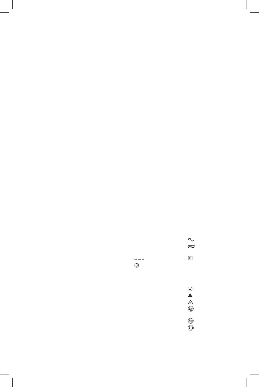
The label on your tool may include the following symbols. The
symbols and their definitions are asfollows:
V ......................... volts
Hz .......................hertz
min ..................... minutes
or DC ......direct current
...................... Class I Construction
(grounded)
…/min ..............per minute
BPM .................... beats per minute
IPM ..................... impacts per minute
RPM .................... revolutions per
minute
sfpm ................... surface feet per
minute
SPM .................... strokes per minute
A ......................... amperes
W ........................watts
or AC ...........alternating current
or AC/DC .... alternating or
direct current
...................... Class II
Construction
(double insulated)
n
o
.......................no load speed
n .........................rated speed
......................earthing terminal
...................... safety alert symbol
..................... visible radiation
..................... respiratory
protection
.....................eye protection
.....................hearing protection
BATTERIES AND CHARGERS
The battery pack is not fully charged out of the carton.
Before using the battery pack and charger, read the
safety instructions below and then follow charging
ENGLISH
4
proceduresoutlined.When ordering replacement battery
packs, be sure to include the catalog number andvoltage.
Your tool uses a
DeWALT
charger. Be sure to read all safety
instructions before using your charger. Consult the chart
at the end of this manual for compatibility of chargers and
batterypacks.
Important Safety Instructions for All
Battery Packs
WARNING: Read all safety warnings and all
instructions for the battery pack, charger and
power tool. Failure to follow the warnings and
instructions may result in electric shock, fire and/
or serious injury.
Do not charge or use the battery pack in explosive
atmospheres, such as in the presence of flammable
liquids, gases or dust. Inserting or removing the battery
pack from the charger may ignite the dust orfumes.
NEVER force the battery pack into the charger. DO
NOT modify the battery pack in any way to fit into
a non-compatible charger as battery pack may
rupture causing serious personal injury. Consult
the chart at the end of this manual for compatibility of
batteries andchargers.
Charge the battery packs only in designated
DeWALT
chargers.
DO NOT splash or immerse in water or otherliquids.
Do not store or use the tool and battery pack in
locations where the temperature may reach or
exceed 104°F (40°C) (such as outside sheds or metal
buildings in summer). For best life store battery packs in
a cool, drylocation.
NOTE: Do not store the battery packs in a tool with
the trigger switch locked on. Never tape the trigger
switch in the ONposition.
WARNING: Fire hazard. Never attempt to open the
battery pack for any reason. If the battery pack case
is cracked or damaged, do not insert into the charger.
Do not crush, drop or damage the battery pack. Do
not use a battery pack or charger that has received a
sharp blow, been dropped, run over or damaged in
any way (e.g., pierced with a nail, hit with a hammer,
stepped on). Damaged battery packs should be
returned to the service center forrecycling.
Transportation
WARNING: Fire hazard. Do not store or carry the
battery pack so that metal objects can contact
exposed battery terminals. For example, do
not place the battery pack in aprons, pockets, tool
boxes, product kit boxes, drawers, etc., with loose
nails, screws, keys, etc. Transporting batteries
can possibly cause fires if the battery terminals
inadvertently come in contact with conductive
materials such as keys, coins, hand tools and the
like. The US Department of Transportation Hazardous
Material Regulations (HMR) actually prohibit
transporting batteries in commerce or on airplanes in
carry-on baggage UNLESS they are properly protected
from short circuits. So when transporting individual
battery packs, make sure that the battery terminals
are protected and well insulated from materials that
could contact them and cause a short circuit.
Shipping the
DeWALT
FLEXVOLT™ Battery
The D
e
WALT FLEXVOLT™ battery has two modes: Use and
Shipping.
Use Mode: When the FLEXVOLT™ battery stands alone or is
in a D
e
WALT 20V Max* product, it will operate as a 20V Max*
battery. When the FLEXVOLT™ battery is in a 60V Max* or a
120V Max* (two 60V Max* batteries) product, it will operate
as a 60V Max* battery.
Shipping Mode: When
the cap is attached to
the FLEXVOLT™ battery,
the battery is in Shipping
Mode. Strings of cells are
electrically disconnected within the pack resulting in three
batteries with a lower Watt hour (Wh) rating as compared
to one battery with a higher Watt hour rating. This increased
quantity of three batteries with the lower Watt hour rating
can exempt the pack from certain shipping regulations that
are imposed upon the higher Watt hour batteries.
The battery label indicates two Watt Hour Ratings (see
example). Depending on how the battery is shipped, the
appropriate Whr rating must be used to determine the
applicable shipping requirements. If utilizing the shipping
cap, the pack will be considered 3 batteries at the Whr
indicated for “Shipping”. If shipping without the cap or in
a tool, the pack will be considered one battery at the Watt
hour rating indicated next to “Use”.
USE: 120 Wh Shipping: 3 x 40 Wh
Example of Use and Shipping Label Marking
Transport Wh rating indicates 3 x 40 Wh, meaning 3
batteries of 40 Watt hours each. The Use Wh rating indicates
120 Watt hour (1 battery implied).
Fuel Gauge Battery Packs (Fig. B)
Some
DeWALT
battery packs include a fuel gauge which
consists of three green LED lights that indicate the level of
charge remaining in the batterypack.
The fuel gauge is an indication of approximate levels of
charge remaining in the battery pack according to the
followingindicators:
75–100% charged
51–74% charged
< 50% charged
Pack needs to be charged
ENGLISH
5
To actuate the fuel gauge, press and hold the fuel gauge
button
11
. A combination of the three green LED lights will
illuminate designating the level of charge left. When the
level of charge in the battery is below the usable limit, the
fuel gauge will not illuminate and the battery will need to
berecharged.
Fig. B
11
NOTE: The fuel gauge is only an indication of the charge left
on the battery pack. It does not indicate tool functionality
and is subject to variation based on product components,
temperature and end-userapplication.
For more information regarding fuel gauge battery packs,
please contact call 1-800-4-
DeWALT
(1-800-433-9258) or
visit our website www.dewalt.com.
The RBRC® Seal
The RBRC® (Rechargeable Battery
Recycling Corporation) Seal on the nickel
cadmium, nickel metal hydride or lithium-
ion batteries (or battery packs) indicates
that the costs to recycle these batteries
(or battery packs) at the end of their useful life have already
been paid by
DeWALT
. In some areas, it is illegal to place
spent nickel cadmium, nickel metal hydride or lithium-ion
batteries in the trash or municipal solid waste stream and
the Call2Recycle® program provides an environmentally
consciousalternative.
Call 2 Recycle, Inc., in cooperation with
DeWALT
and other
battery users, has established the program in the United
States and Canada to facilitate the collection of spent nickel
cadmium, nickel metal hydride or lithium-ion batteries. Help
protect our environment and conserve natural resources by
returning the spent nickel cadmium, nickel metal hydride
or lithium-ion batteries to an authorized
DeWALT
service
center or to your local retailer for recycling. You may also
contact your local recycling center for information on
where to drop off the spent battery. RBRC® is a registered
trademark of Call 2 Recycle,Inc.
Important Safety Instructions for All
Battery Chargers
WARNING: Read all safety warnings and all
instructions for the battery pack, charger and
power tool. Failure to follow the warnings and
instructions may result in electric shock, fire and/
or serious injury.
DO NOT attempt to charge the battery pack with
any chargers other than the ones in this manual.
The charger and battery pack are specifically designed to
worktogether.
These chargers are not intended for any uses other
than charging
DeWALT
rechargeable batteries.
Any other uses may result in risk of fire, electric shock
orelectrocution.
Do not expose the charger to rain orsnow.
Pull by the plug rather than the cord when
disconnecting the charger. This will reduce the risk of
damage to the electric plug andcord.
Make sure that the cord is located so that it will not
be stepped on, tripped over or otherwise subjected
to damage orstress.
Do not use an extension cord unless it is absolutely
necessary. Use of improper extension cord could result in
risk of fire, electric shock orelectrocution.
When operating a charger outdoors, always provide
a dry location and use an extension cord suitable
for outdoor use. Use of a cord suitable for outdoor use
reduces the risk of electricshock.
An extension cord must have adequate wire size
(AWG or American Wire Gauge) for safety. The smaller
the gauge number of the wire, the greater the capacity
of the cable, that is, 16 gauge has more capacity than 18
gauge. An undersized cord will cause a drop in line voltage
resulting in loss of power and overheating. When using
more than one extension to make up the total length,
be sure each individual extension contains at least the
minimum wire size. The following table shows the correct
size to use depending on cord length and nameplate
ampere rating. If in doubt, use the next heavier gauge. The
lower the gauge number, the heavier thecord.
Minimum Gauge for Cord Sets
Volts
Total Length of Cord in Feet
(meters)
120 V 25 (7.6) 50 (15.2) 100 (30.5) 150 (45.7)
240 V 50 (15.2) 100 (30.5) 200 (61.0) 300 (91.4)
Ampere Rating
American Wire Gauge
More
Than
Not
More
Than
0 6 18 16 16 14
6 10 18 16 14 12
10 12 16 16 14 12
12 16 14 12 Not Recommended
Do not place any object on top of the charger or
place the charger on a soft surface that might block
the ventilation slots and result in excessive internal
heat. Place the charger in a position away from any heat
source. The charger is ventilated through slots in the top
and the bottom of thehousing.
Do not operate the charger with a damaged cord
orplug.
Do not operate the charger if it has received a sharp
blow, been dropped or otherwise damaged in any
way. Take it to an authorized servicecenter.
Do not disassemble the charger; take it to an
authorized service center when service or repair
is required. Incorrect reassembly may result in a risk of
electric shock, electrocution orfire.
Disconnect the charger from the outlet before
attempting any cleaning. This will reduce the risk of
ENGLISH
6
electric shock. Removing the battery pack will not reduce
thisrisk.
NEVER attempt to connect 2 chargerstogether.
The charger is designed to operate on standard
120V household electrical power. Do not attempt to
use it on any other voltage. This does not apply to the
vehicularcharger.
WARNING: Shock hazard. Do not allow any liquid to
get inside the charger. Electric shock mayresult.
WARNING: Burn hazard. Do not submerge the
battery pack in any liquid or allow any liquid to
enter the battery pack. Never attempt to open the
battery pack for any reason. If the plastic housing of
the battery pack breaks or cracks, return to a service
center for recycling.
CAUTION: Burn hazard. To reduce the risk of injury,
charge only
DeWALT
rechargeable battery packs.
Other types of batteries may overheat and burst
resulting in personal injury and propertydamage.
NOTICE: Under certain conditions, with the charger
plugged into the power supply, the charger can
be shorted by foreign material. Foreign materials
of a conductive nature, such as, but not limited to,
grinding dust, metal chips, steel wool, aluminum
foil or any buildup of metallic particles should be
kept away from the charger cavities. Always unplug
the charger from the power supply when there is no
battery pack in the cavity. Unplug the charger before
attempting toclean.
Charging a Battery (Fig. C)
1. Plug the charger into an appropriate outlet before
inserting battery pack.
2. Insert the battery pack
12
into the charger, making sure
the battery pack is fully seated in the charger. The red
(charging) light will blink continuously indicating that
the charging process has started.
3. The completion of charge will be indicated by the red
light remaining ON continuously. The battery pack is
fully charged and may be used at this time or left in the
charger. To remove the battery pack from the charger,
push the battery release button
13
on the battery pack.
NOTE: To ensure maximum performance and life of lithium-
ion battery packs, charge the battery pack fully before
firstuse.
Fig. C
12
13
Charger Operation
Refer to the indicators below for the charge status of the
battery pack.
DCB101
Charging
Fully Charged
Hot/Cold Pack Delay
Problem Pack or Charger
DCB107, DCB112, DCB113, DCB115, DCB118
Charging
Fully Charged
Hot/Cold Pack Delay*
* DCB107, DCB112, DCB113, DCB115, DCB118: The red
light will continue to blink, but a yellow indicator light will
be illuminated during this operation. Once the battery
pack has reached an appropriate temperature, the yellow
light will turn off and the charger will resume the charging
procedure.
The compatible charger(s) will not charge a faulty battery
pack. The charger will indicate faulty battery pack by
refusing to light or by displaying a problem pack or charger
blink pattern.
NOTE: This could also mean a problem with a charger.
If the charger indicates a problem, take the charger and
battery pack to be tested at an authorized service center.
Hot/Cold Pack Delay
When the charger detects a battery pack that is too hot
or too cold, it automatically starts a Hot/Cold Pack Delay,
suspending charging until the battery pack has reached an
appropriate temperature. The charger then automatically
switches to the pack charging mode. This feature ensures
maximum battery pack life.
A cold battery pack will charge at a slower rate than a warm
battery pack. The battery pack will charge at that slower rate
throughout the entire charging cycle and will not return to
maximum charge rate even if the battery pack warms.
The DCB118 charger is equipped with an internal fan
designed to cool the battery pack. The fan will turn on
automatically when the battery pack needs to be cooled.
Never operate the charger if the fan does not operate
properly or if ventilation slots are blocked. Do not permit
foreign objects to enter the interior of the charger.
Lithium-Ion Battery Packs Only
Li-Ion tools are designed with an Electronic Protection
System that will protect the battery pack against
overloading, overheating or deep discharge.
The tool will automatically turn off if the Electronic
Protection System engages. If this occurs, place the lithium-
ion battery pack on the charger until it is fully charged.
ENGLISH
7
Wall Mounting
DCB107, DCB112, DCB113, DCB115, DCB118
These chargers are designed to be wall mountable or to
sit upright on a table or work surface. If wall mounting,
locate the charger within reach of an electrical outlet,
and away from a corner or other obstructions which may
impede air flow. Use the back of the charger as a template
for the location of the mounting screws on the wall. Mount
the charger securely using drywall screws (purchased
separately) at least 1" (25.4 mm) long, with a screw head
diameter of 0.28–0.35" (7–9mm), screwed into wood to an
optimal depth leaving approximately 7/32" (5.5 mm) of the
screw exposed. Align the slots on the back of the charger
with the exposed screws and fully engage them in the slots.
Charger Cleaning Instructions
WARNING: Shock hazard. Disconnect the charger
from the AC outlet before cleaning. Dirt and grease
may be removed from the exterior of the charger using
a cloth or soft non-metallic brush. Do not use water or
any cleaning solutions.
Important Charging Notes
1. Longest life and best performance can be obtained if
the battery pack is charged when the air temperature is
between 65°F and 75°F (18° 24°C). DO NOT charge
the battery pack in an air temperature below +40°F
(+4.5°C), or above +104°F (+40°C). This is important
and will prevent serious damage to the battery pack.
2. The charger and battery pack may become warm to the
touch while charging. This is a normal condition, and
does not indicate a problem. To facilitate the cooling of
the battery pack after use, avoid placing the charger or
battery pack in a warm environment such as in a metal
shed or an uninsulated trailer.
3. If the battery pack does not charge properly:
a. Check operation of receptacle by plugging in a lamp
or other appliance;
b. Check to see if receptacle is connected to a light
switch which turns power off when you turn out the
lights;
c. Move the charger and battery pack to a location
where the surrounding air temperature is
approximately 65°F – 75°F (18° – 24°C);
d. If charging problems persist, take the tool, battery
pack and charger to your local service center.
4. The battery pack should be recharged when it fails to
produce sufficient power on jobs which were easily
done previously. DO NOT CONTINUE to use under these
conditions. Follow the charging procedure. You may
also charge a partially used pack whenever you desire
with no adverse effect on the battery pack.
5. Foreign materials of a conductive nature such as, but
not limited to, grinding dust, metal chips, steel wool,
aluminum foil, or any buildup of metallic particles
should be kept away from charger cavities. Always
unplug the charger from the power supply when there
is no battery pack in the cavity. Unplug the charger
before attempting to clean.
6. Do not freeze or immerse the charger in water or any
other liquid.
Storage Recommendations
1. The best storage place is one that is cool and dry, away
from direct sunlight and excess heat or cold.
2. For long storage, it is recommended to store a fully
charged battery pack in a cool dry place out of the
charger for optimal results.
NOTE: Battery packs should not be stored completely
depleted of charge. The battery pack will need to be
recharged before use.
SAVE THESE INSTRUCTIONS FOR
FUTURE USE
COMPONENTS (FIG. A)
WARNING: Never modify the power tool or any part
of it. Damage or personal injury couldresult.
Refer to Figure A at the beginning of this manual for a
complete list ofcomponents.
INTENDED USE
The DCD460 heavy-duty stud and joist drill is designed for
professional drilling at various work sites (i.e., construction
sites). DO NOT use under wet conditions or in presence of
flammable liquids or gases.
These heavy-duty stud and joist drills are professional power
tools. DO NOT let children come into contact with the tool.
Supervision is required when inexperienced operators use
this tool.
ASSEMBLY AND ADJUSTMENTS
WARNING: To reduce the risk of serious personal
injury, turn unit off and remove the battery pack
before making any adjustments or removing/
installing attachments or accessories. An
accidental start-up can causeinjury.
Torque
WARNING: This is a high-torque drill. To reduce the
risk of serious personal injury, ALWAYS hold tool
firmly with both hands in the proper position for
operation as shown.
Torque is the twisting action the drill produces in regards
to the rotating bit. As the drill bit meets resistance in the
material being drilled, the motor responds by adjusting the
output torque to meet the requirement up to the maximum
capacity of the motor and gear system.
Bracing the Tool (Fig. D, J)
WARNING: To reduce the risk of serious personal
injury, ALWAYS hold or brace the tool securely in
anticipation of a sudden reaction.
With hands in the proper hand position (also refer to Fig. J),
brace the tool as shown in FigureD.
ENGLISH
8
The bit rotates clockwise when the tool is in the forward
position and counterclockwise when the tool is in the
reverse position. If the bit binds, the tool will slow to a
manageable level. Using proper hand position, brace the
side handle
14
or tool body against a stud for better
support (Fig.D).
REVERSE
FORWARD
Fig. D
14
14
Clutch
The DCD460 is equipped with a mechanical slip clutch. The
clutch is active when the low speed (1) is selected. When
the bit or cutter bites into the workpiece, the clutch will slip
and a ratcheting sound will be heard. Release the trigger.
Continued clutching of the tool will reduce the life of this
feature.
E-Clutch® System (Fig. 1)
The DCD460 is equipped with the
DeWALT
E-Clutch®
system. This feature senses the motion of the tool and
reduces the motor torque to a manageable level if
necessary. The E-Clutch® indicator
7
will illuminate to
indicate status.
INDICATOR DIAGNOSIS SOLUTION
OFF Tool is
functioning
normally
Follow all warnings and
instructions when operating
the tool.
SOLID E-Clutch®
System has
been activated
(ENGAGED)
With the tool properly
supported, release trigger.
The tool will function
normally when the trigger
is depressed again and the
indicator light will go out
Bail Handle (Fig. E)
A bail handle
1
is provided for carrying the tool and for
use as an additional handle. Assemble the bail handle in
one of the positions shown in FigureE. When changing the
location of the bail handle from one position to the other,
completely remove the two bail handle bolts
5
securing it.
Flip the handle over and reinstall.
Fig. E
1
5
5
Side Handle (Fig. F)
WARNING: To reduce the risk of personal injury,
always operate the tool with the side handle properly
installed and tightened. Failure to do so may result
in the side handle slipping during tool operation and
subsequent loss of control. Hold tool with both hands
to maximize control.
The two position side handle
14
can be assembled into
either side of tool. Thread the side handle
14
into the bail
handle bolt
5
or directly into threaded holes
15
on desired
side. Tighten securely by hand.
Fig. F
5
14
15
Speed Selector (Fig. A)
NOTICE: Risk of tool damage. Do not rotate the speed
selector lever while the drill is running or coasting,
damage may occur to the tool.
Rotate the speed selector lever
2
to the desired speed:
1 = low speed
2 = high speed
NOTE: The first time the tool is run after changing speeds,
you may hear a click on start up. This is normal and does not
indicate a problem.
ENGLISH
9
Variable Speed Trigger Switch (Fig. A)
Depressing the variable speed trigger switch
4
turns the
tool on, releasing the variable speed trigger switch turns
the tool off. The variable speed trigger switch permits speed
control—the farther the trigger is depressed, the higher the
speed of the drill.
Forward/Reverse Button (Fig. A)
A forward/reverse button
3
determines the direction of the
tool. It is located in front of the trigger switch.
To select forward rotation, release the trigger switch
4
and
depress the forward/reverse button on the right side of the
tool.
To select reverse, depress the forward/reverse button on
the left side of the tool. When changing the position of the
button, be sure the trigger is released.
NOTE: The first time the tool is run after changing the
direction of rotation, you may hear a click on start up. This is
normal and does not indicate a problem.
Keyed Chuck
Open the chuck jaws by turning collar by hand and insert
the shank of the bit about 3/4" (19 mm) into chuck. Tighten
the chuck collar by hand. Place chuck key (
10
, Fig.A) in
each of the three holes, and tighten in clockwise direction.
It’s important to tighten chuck with all three holes. To
release the bit, turn the chuck counterclockwise in just one
hole, then loosen the chuck by hand.
NOTE: When using hex shank or three-sided shank bits, be
sure to align the flat sides of the bit with the chuck jaws to
ensure the bit is properly engaged by the jaws.
Removal of Keyed Chuck (Fig. G)
Remove the left-handed chuck screw using a T25 torx
wrench, rotating clockwise to loosen.Tighten the chuck
around the shorter end of a hex wrench (not supplied)
of 3/8" (10 mm) size. With the tool braced securely, use
a soft hammer and strike the hex wrench sharply in the
counterclockwise direction when viewed from the front
of the tool. This will loosen the chuck so that it can be
removed by hand.
Keyed Chuck Installation (Fig. H)
Screw the chuck on by hand as far as it will go. Insert the
shorter end of a hex wrench (not supplied) of 3/8" (10 mm)
size and strike it in the clockwise direction with a soft
hammer. Reinstall the left handed clutch screw.
FIG. H
FIG. G
Worklight (Fig. A)
CAUTION: Do not stare into worklight. Serious eye
injury could result.
The worklight
9
is located on the foot of the tool. The
worklight is activated when the trigger switch is depressed,
and will automatically turn off 20 seconds after the trigger
switch is released. If the trigger switch remains depressed,
the worklight will remain on.
NOTE: The worklight is for lighting the immediate work
surface and is not intended to be used as a flashlight.
OPERATION
WARNING: To reduce the risk of serious personal
injury, turn unit off and remove the battery pack
before making any adjustments or removing/
installing attachments or accessories. An
accidental start-up can causeinjury.
Installing and Removing the Battery Pack
(Fig. I)
NOTE: For best results, make sure your battery pack is
fullycharged.
To install the battery pack
12
into the tool handle, align the
battery pack with the rails inside the tool’s handle and slide
it into the handle until the battery pack is firmly seated in
the tool and ensure that it does notdisengage.
To remove the battery pack from the tool, press the release
button
13
and firmly pull the battery pack out of the tool
handle. Insert it into the charger as described in the charger
section of thismanual.
Squeeze the tool trigger for three seconds to dissipate
the slight electric charge that may still be in the tool. The
worklight may come on for a brief moment.
Fig. I
13
12
Proper Hand Position (Fig. J)
WARNING: To reduce the risk of serious personal injury,
ALWAYS use proper hand position as shown.
WARNING: To reduce the risk of serious personal injury,
ALWAYS hold securely in anticipation of a sudden
reaction.
Always hold tool firmly with both hands in the proper
position for operation as shown.
ENGLISH
10
Fig. J
Drilling
WARNING: TO REDUCE THE RISK OF PERSONAL
INJURY, ALWAYS ensure workpiece is anchored or
clamped firmly. If drilling thin material, use a wood
“back-up” block to prevent damage to the material.
1. Use sharp drill bits only. For WOOD, use twist drill bits,
spade bits, power auger bits, or hole saws. For METAL,
use steel twist drill bits or hole saws.
2. Always apply pressure in a straight line with the bit. Use
enough pressure to keep drill biting, but do not push
hard enough to stall the motor or deflect the bit.
3. Hold tool firmly with both hands to control the twisting
action of the drill.
4. IF DRILL STALLS, it is usually because it is being
overloaded or improperly used. RELEASE TRIGGER
IMMEDIATELY, remove drill bit from work, and
determine cause of stalling. DO NOT CLICK TRIGGER ON
AND OFF IN AN ATTEMPT TO START A STALLED DRILL
— THIS CAN DAMAGE THE DRILL.
5. To minimize stalling or breaking through the material,
reduce pressure on drill and ease the bit through the
last fractional part of the hole.
6. Keep the motor running when pulling the bit back out
of a drilled hole. This will help prevent jamming.
Drilling in Metal
Start drilling with slow speed and increase to full power
while applying firm pressure on the tool. A smooth even
flow of metal chips indicates the proper drilling rate. Use a
cutting lubricant when drilling metals. The exceptions are
cast iron and brass which should be drilled dry.
NOTE: Large [5/16" (8 mm) to 1/2" (13 mm)] holes in steel
can be made easier if a pilot hole [5/32" (4 mm) to 3/16" (5
mm)] is drilled first.
Drilling in Wood
Start drilling with slow speed and increase to full power
while applying firm pressure on the tool. Holes in wood can
be made with the same twist drills used for metal. These
bits may overheat unless pulled out frequently to clear chips
from the flutes. Work that is apt to splinter should be backed
up with a block of wood.
MAINTENANCE
WARNING: To reduce the risk of serious personal
injury, turn unit off and remove the battery pack
before making any adjustments or removing/
installing attachments or accessories. An
accidental start-up can causeinjury.
Lubrication
Your tool was properly lubricated before leaving the factory.
In from two to six months, depending upon use, take or
send your tool to a
DeWALT
Service Center or other qualified
service organization for a complete cleaning, inspection and
relubrication.
Cleaning
WARNING: Blow dirt and dust out of all air vents with
clean, dry air at least once a week. To minimize the risk
of eye injury, always wear ANSI Z87.1 approved eye
protection when performingthis.
WARNING: Never use solvents or other harsh
chemicals for cleaning the non-metallic parts of
the tool. These chemicals may weaken the plastic
materials used in these parts. Use a cloth dampened
only with water and mild soap. Never let any liquid
get inside the tool; never immerse any part of the tool
into aliquid.
Accessories
WARNING: Since accessories, other than those
offered by
DeWALT
, have not been tested with this
product, use of such accessories with this tool could be
hazardous. To reduce the risk of injury, only
DeWALT
recommended accessories should be used with
thisproduct.
Recommended accessories for use with your tool
are available at extra cost from your local dealer or
authorized service center. If you need assistance in
locating any accessory, please contact
DeWALT
Industrial
Tool Co., 701East Joppa Road, Towson, MD 21286, call
1-800-4-
DeWALT
(1-800-433-9258) or visit our website:
www.dewalt.com.
ENGLISH
11
MAXIMUM RECOMMENDED
CAPACITIES
LOW SPEED HIGH SPEED
RPM 0–300 0–1250
WOOD, FLAT BORING
1-1/2"
(38 mm)
HOLE SAWS 6-1/4"
(152.4 mm)
SHIP AUGER
1-1/2"
(38 mm)
SELF-FEED BITS 4-5/8"
(102 mm)
2-9/16"
(65 mm)
CLUTCH OPERATIVE YES NO
E-Clutch® System (DCD460) YES YES
NOTE: For holes in metal larger than 1/2" (13mm) use
hole saws.
Repairs
The charger and battery pack are notserviceable.
WARNING: To assure product SAFETY and
RELIABILITY, repairs, maintenance and adjustment
(including brush inspection and replacement) should
be performed by a
DeWALT
factory service center
or a
DeWALT
authorized service center. Always use
identical replacementparts.
Register Online
Thank you for your purchase. Register your product nowfor:
WARRANTY SERVICE: Registering your product will
help you obtain more efficient warranty service in case
there is a problem with yourproduct.
CONFIRMATION OF OWNERSHIP: In case of
an insurance loss, such as fire, flood or theft, your
registration of ownership will serve as your proof
ofpurchase.
FOR YOUR SAFETY: Registering your product will
allow us to contact you in the unlikely event a safety
notification is required under the Federal Consumer
SafetyAct.
Register online at www.dewalt.com/register.
Three Year Limited Warranty
DeWALT
will repair, without charge, any defects due to
faulty materials or workmanship for three years from the
date of purchase. This warranty does not cover part failure
due to normal wear or tool abuse. For further detail of
warranty coverage and warranty repair information, visit
www.dewalt.com or call 1-800-4-
DeWALT
(1-800-433-9258).
This warranty does not apply to accessories or damage
caused where repairs have been made or attempted by
others. This warranty gives you specific legal rights and
you may have other rights which vary in certain states
orprovinces.
In addition to the warranty,
DeWALT
tools are covered
byour:
1 YEAR FREE SERVICE
DeWALT
will maintain the tool and replace worn parts
caused by normal use, for free, any time during the first year
afterpurchase.
2 YEARS FREE SERVICE ON DEWALT BATTERY PACKS
DC9071, DC9091, DC9096, DC9182, DC9280, DC9360,
DCB120, DCB127, DCB201, DCB203, DCB203BT, DCB207,
DCB361
3 YEARS FREE SERVICE ON DEWALT BATTERY PACKS
DCB200, DCB204, DCB204BT, DCB205, DCB606
NOTE: Battery warranty voided if the battery pack is
tampered with in any way.
DeWALT
is not responsible
for any injury caused by tampering and may prosecute
warranty fraud to the fullest extent permitted bylaw.
90 DAY MONEY BACK GUARANTEE
If you are not completely satisfied with the performance of
your
DeWALT
Power Tool, Laser, or Nailer for any reason, you
can return it within 90 days from the date of purchase with
a receipt for a full refund – no questionsasked.
LATIN AMERICA: This warranty does not apply to products
sold in Latin America. For products sold in Latin America,
see country specific warranty information contained in
the packaging, call the local company or see website for
warrantyinformation.
FREE WARNING LABEL REPLACEMENT: If your warning
labels become illegible or are missing, call 1-800-4-
DeWALT
(1-800-433-9258) for a freereplacement.
D
e
WALT Industrial Tool Co., 701 East Joppa Road, Baltimore, MD 21286
(APR16) Part No. N453109 DCD460 Copyright © 2016 D
e
WALT
The following are trademarks for one or more D
e
WALT power tools: the yellow and black color scheme, the “D” shaped air
intake grill, the array of pyramids on the handgrip, the kit box configuration, and the array of lozenge-shaped humps on the
surface of the tool.
D
e
WALT BATTERY AND CHARGER SYSTEMS
Chargers/Charge Time (Minutes)
Chargeurs/Durée de charge (Minutes)
Cargadores de baterías/Tiempo de carga (Minutos)
Battery
Cat #
Output
Voltage
120 Volts 12 Volts
DC9000
DC9310
DC9320
DCB095
DCB101
DCB102
DCB103
DCB107
DCB112
DCB113
DCB114
DCB115
DCB118
DCB132
DCB119
DW0249
DCB606 60/20 X X X X 100 100 100 272 170 140 X 90 60 90 X X
DCB404 40 X X X X X X X X X X 90 X X X X X
DCB406 40 X X X X X X X X X X 130 X X X X X
DC9360 36 45 X X X X X X X X X X X X X X X
DCB361 36 45 X X X X X X X X X X X X X X X
DC9280 28 60 X X X X X X X X X X X X X X X
DW0242 24 X X X X X X X X X X X X X X X 60
DCB200 20 X X X X 60 60 60 140 90 67 X 45 45/30** 45 90 X
DCB201 20 X X X X 30 30 30 70 45 35 X 22 22 22 45 X
DCB203 20 X X X X 35 35 35 90 60 45 X 30 30 30 60 X
DCB203BT* 20 X X X X 35 35 35 90 60 45 X 30 30 30 60 X
DCB204 20 X X X X 70 70 70 185 120 90 X 60 60/40** 60 120 X
DCB204BT* 20 X X X X 70 70 70 185 120 90 X 60 60 60 120 X
DCB205 20 X X X X 95 95 95 240 150 112 X 75 75/47** 75 150 X
DCB207 20 X X X X 30 30 30 60 40 30 X 22 22 22 X X
DC9182 18 X 40 40 X X X 40 X X X X X X X X 40
DCB120 12 X X X X 30 30 30 60 45 35 X 20 X X 45 X
DCB127 12 X X X X 35 35 35 90 60 50 X 30 X X 60 X
DCB080 8 X X X 60 X X X X X X X X X X X X
*BT - Bluetooth® NOTE: The Bluetooth® word mark and logos are registered trademarks owned by the Bluetooth®,
SIG, Inc. and any use of such marks by
DeWALT
is under license. Other trademarks and trade names are those of their
respective owners.
**Battery Datecode 201536 or later.
“X” Indicates that the battery pack is not compatible with that specific charger. All charge times are
approximate. Actual charge time may vary. Read the instruction manual for more specific information.
“X” indique que le bloc-piles n’est pas compatible avec ce chargeur. Les durées de charge sont approximatives; la durée de
charge rélle peut varier. Lire le manuel d’utilisation pour obtenir des renseignements plus précis.
Una “X” indica que el paquete de baterías no es compatible con ese determinado cargador. El tiempo de duración de
carga es aproximado; la duración de carga real puede variar. Lea el manual de instrucciones para obtener información más
precisa.
* Maximum initial battery voltage (measured without a workload) is 20, 60 or 120 volts. Nominal voltage is 18, 54 and 108.
(The 120V Max* is based on using 2
DeWALT
60V Max* lithium-ion batteries combined.)
* La tension initiale maximum du bloc-piles (mesurée à vide) est de 20, 60 ou 120 volts. La tension nominale est de 18, 54 et 108.
(Le 120V Max* se base sur l’utilisation combinée de 2 blocs-piles au lithium-ion
DeWALT
de 60V Max*).
* El máximo voltaje inicial de la batería (medido sin carga de trabajo) es 20, 60 o 120 voltios. El voltaje nominal es de 18, 54 y
108. (Los 120 V Máx* se basan en el uso de 2 baterías de iones de litio
DeWALT
de 60 V Máx* combinadas).
  • Page 1 1
  • Page 2 2
  • Page 3 3
  • Page 4 4
  • Page 5 5
  • Page 6 6
  • Page 7 7
  • Page 8 8
  • Page 9 9
  • Page 10 10
  • Page 11 11
  • Page 12 12
  • Page 13 13
  • Page 14 14
  • Page 15 15
  • Page 16 16
  • Page 17 17
  • Page 18 18
  • Page 19 19
  • Page 20 20
  • Page 21 21
  • Page 22 22
  • Page 23 23
  • Page 24 24
  • Page 25 25
  • Page 26 26
  • Page 27 27
  • Page 28 28
  • Page 29 29
  • Page 30 30
  • Page 31 31
  • Page 32 32
  • Page 33 33
  • Page 34 34
  • Page 35 35
  • Page 36 36
  • Page 37 37
  • Page 38 38
  • Page 39 39
  • Page 40 40
  • Page 41 41
  • Page 42 42
  • Page 43 43
  • Page 44 44

DeWalt DCD460B User manual

Category
Power tools
Type
User manual

Ask a question and I''ll find the answer in the document

Finding information in a document is now easier with AI