
B&K Components, Ltd.
AVR505 SERIES 2
AVR507 SERIES 2
User Manual
Five or Seven Channel
Surround A/V Processor Receiver
13791 1104

USER MANUAL - AVR505 Series2, AVR507 Series2
© 2004 B&K Components Ltd. All rights reserved.
The information in this manual is copyright protected. No part of this manual may be copied or reproduced in any form without prior
written consent from B&K Components, Ltd.
B&K Components Ltd. SHALL NOT BE LIABLE FOR OPERATIONAL, TECHNICAL OR EDITORIAL ERRORS/OMISSIONS MADE
IN THIS MANUAL. The information in this manual is subject to change without prior notice.
Accessories Included
SIMPLY BETTER! is a registered trademark of B&K Components, Ltd. Manufactured under license from Dolby Laboratories. "Dolby", "Surround EX",
“Pro Logic” and the double-D symbol are trademarks of Dolby Laboratories. Manufactured under license from Digital Theater Systems, Inc. US Pat.
No.5,451,942, 5,956,674, 5,974,380, 5,978,762, 6,487,535 and other U.S and worldwide patents issued and pending. “DTS”, "DTS-ES" and "Neo:6"
trademarks of Digital Theater Systems, Inc. Copyright 1996, 2003 Digital Theater Systems, Inc. All Rights Reserved. Motorola® , * DigitalDNA™,
"Powered by Motorola™, Motorola name and logo are registered trademarks of Motorola, Inc. All Rights Reserved.
Limited Warranty
B&K Components Ltd., referred to herein as B&K, warrants your B&K equipment against all defects in material and workmanship for a period of five
years from the date of purchase. This warranty applies only to the original purchaser and only to equipment in normal residential use and service.
Defective equipment must be returned to B&K, prepaid, accompanied by proof of purchase and sufficient payment to cover the cost of return shipping
and handling, and will be repaired or replaced at the discretion of B&K whose decision as to the method of reparation will be final.
This warranty shall not apply to any equipment which is found to have been improperly installed, incorrectly fused, misused, abused, or subjected to
harmful elements, used in any way not in accordance with instructions supplied with the unit, or to have been modified, repaired or altered in any way
without the expressed, written consent of B&K. This warranty does not apply to the cabinet or appearance items such as the faceplate or control
buttons, nor does it cover any expenses incurred in shipping the unit to and from the manufacturer's service department.
This warranty on B&K Components, Ltd. products is NOT VALID if the products have been purchased from an unauthorized dealer or an E-tailer or if
the original factory serial number has been removed, defaced or replaced in any way. B&K Components, Ltd. sells its products through authorized
dealers in order to ensure that consumers obtain proper dealer service and support. Buying from an authorized B&K Components, Ltd. dealer insures
that you have a FACTORY WARRANTY on your B&K Components, Ltd. product. If you have any questions concerning your Factory Warranty call
B&K Components, Ltd. at 716-656-0026.
Upgradeability: B&K is one of the first manufacturers in the audio/video industry to consistently offer software and hardware upgrades to its
processing of audio signals. Through upgrades B&K delivers exceptional value to its customers. But what is "upgradeability"? Upgradeability is not a
guarantee; we define it as a philosophy of designing and manufacturing products so that as audio technology evolves, B&K can provide enhance-
ments and improvements to its products that are economically viable.
THE EXPRESS FACTORY WARRANTY HEREIN CONTAINED IS IN LIEU OF ANY AND ALL OTHER WARRANTIES, EXPRESSED OR IMPLIED,
INCLUDING ANY WARRANTY OF MERCHANTABILITY, UPGRADEABILITY OR OF FITNESS FOR ANY PARTICULAR PURPOSE. B&K COMPO-
NENTS, LTD. SHALL NOT UNDER ANY CIRCUMSTANCES BE LIABLE FOR DAMAGES, INCLUDING SPECIAL, INCIDENTAL, EXEMPLARY,
PUNITIVE OR CONSEQUENTIAL DAMAGES ARISING OUT OF OR IN CONNECTION WITH THE PURCHASE, USE OR PERFORMANCE OF ANY
B&K PRODUCT.
This warranty gives you specific legal rights. You may also have other rights which vary from State to State. Some States do not allow the exclusion or
limitation of incidental or consequential damages and the foregoing exclusions may not apply to you.
No agent, representative, dealer or employee of B&K has the authority to increase or alter the obligations or terms of this warranty.
Returning Equipment
No equipment may be returned to B&K Components Ltd. without a RETURN AUTHORIZATION (RA). Should you find it necessary to return equip-
ment to B&K, for any reason, a RETURN AUTHORIZATION (RA) number must be issued by B&K in respect to the equipment being returned. You
may request an RA number by calling B&K at the numbers below. We will need the following information to issue your RA number. Please have it
ready before you call.
1. Your name, address, and phone number.
2. The model and serial number of the equipment being returned.
3. A description of the problem being experienced.
4. Your sales receipt.
Your call will be referred to a Technical Service Representative who will work with you to resolve the problem. If it is determined that the unit must be
returned for repair, an RA number will be issued.
ACCESSORIES AND LIMITED WARRANTY
ii
2100 Old Union Road Buffalo, NY 14227 1-800-543-5252 In NY: 716-656-0026 fax: 716-656-1291
e-mail: [email protected] Web Site: www.bkcomp.com
1 - SR10.1 Remote Control
1 - AM Antenna
1 - FM Dipole Antenna
1 - Power Cord
1 - Warranty Card
1 - User Manual
1 - Serial to RJ-45 Adapter
1 - BKcSuite CD-ROM
SBIMPLY ETTER!
BK&

TABLE OF CONTENTS
1
ACCESSORIES AND LIMITED WARRANTY ii
TABLE OF CONTENTS 1
SAFETY PRECAUTIONS 3
FEATURES 4
AUDIO OVERVIEW 5
AUDIO AND SURROUND FORMATS 6
FRONT PANEL DESCRIPTION 10
BACK PANEL DESCRIPTION 11
QUICK START CONSIDERATIONS
12
HARDWARE CONNECTIONS 13
SOURCE CONNECTIONS 13
Source Connection Diagram 13
SACD or DVD-Audio Connection 13
VIDEO MONITOR CONNECTION 14
Component Video Monitor Connection 14
S-Video Monitor Connection 14
Composite Video Monitor Connection 14
SURROUND SPEAKER CONNECTIONS 15
7.1 Speaker Output Connections 15
6.1 / 5.1 Speaker Output Connections 16
RCA Surround Outputs / Subwoofer Connection 17
PASS THROUGH / RECORD LOOP CONNECTIONS 18
CONTROL OUTPUT CONNECTIONS 18
IR Emitter Connection 18
+12VDC Control Connection 19
ZONE B CONNECTIONS 19
Zone B Amplification and Video Connection 19
AVR507 Series2 BACK CHANNEL AMPLIFICATION CONVERSION 20
KEYPAD CONNECTION DESCRIPTION 21
ZONE A & ZONE B IR INPUTS 21
AM / FM ANTENNA CONNECTION 21
SETTING UP THE SYSTEM 22
THE MENU SYSTEM 22
MAIN MENU SELECTIONS 23
SYSTEM SETUP 24
SETUP SPEAKERS 25
1. Speaker Size 25
2. Setup Speaker Location 26
3. Setup Speaker Levels 26
4. Setup Crossover + LFE 26
5. Setup Room Equalization 27
6. Room Resonance (Notch Filters) 27
SETUP INPUTS 29
SETUP PRESETS 30
SETUP DISPLAYS 31
SETUP MUSIC MODES 31
MEMORY BACKUP/RESTORE 31
UNIT INFORMATION 32
ADVANCED MENU 32
Zone ‘1’ Home Theater 33
Control Outputs 34
Power on Titles 34

TABLE OF CONTENTS
2
DSP Usage 35
Security Options 35
RS-232 Control Port 36
Plug and Play Timing Setup 37
Zone 2 ‘B’ Second Zone 38
FACTORY RESET
38
SR10.1 REMOTE CONTROL OPERATION
39
UNIT OPERATION 40
Master Power On / Off 40
On / Standby 40
Adjusting Volume 40
Center, Rear and Subwoofer Volume 40
Source Selection 40
Z1 Operation - Theater (menu) 41
Sleep Timer 41
Z2 Operation - Second Zone (menu) 41
Zone Operation Button 41
Tuner Operation 42
Headphone Operation 42
FRONT PANEL DISPLAY OPERATION 43
Processor Status 43
AUDIO MODES & SPEAKER SELECTIONS 45
Audio Mode Usages 45
Speaker Selections 47
Equalization Settings and Adjustments 48
PRESETS 49
Saving a Preset 49
Recalling a Preset 51
Favorite Presets 51
SR10.1 REMOTE EDITOR SOFTWARE 51
Learning IR Codes 53
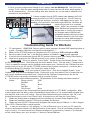
BKcSuite SETUP SOFTWARE 54
Troubleshooting Guide For BKcSuite 55
TROUBLESHOOTING 56
BACK PANEL PICTURE 57
ON SCREEN MENU FLOW CHART 58
SPECIFICATIONS Back
Date of Purchase:
Receiver Model #:
Receiver Serial #:
Purchased From:
Address:
Phone #:
Product Information

SAFETY PRECAUTIONS
WARNING: to prevent fire or shock hazard, do not expose this unit to rain or moisture. Care should
be taken to prevent objects or liquid from entering the enclosure. Never handle the power cord with
wet hands.
• The lightning flash with arrowhead within a triangle is intended to alert the user of the presence of
uninsulated "dangerous voltage" within the product's enclosure that may constitute a risk of electric
shock to you.
• The exclamation point within a triangle is intended to alert the user of the presence of important
operating and maintenance (servicing) instructions in the literature accompanying the unit.
• Caution: To prevent the risk of electric shock, do not remove cover. No user-serviceable parts inside.
Refer servicing to qualified service personnel.
• If an outdoor antenna is installed, be sure it is grounded to provide some protection against voltage
surges and built up static charges. Keep outdoor antennas away from power lines.
• Unplug the receiver from the AC outlet when plugging in or unplugging cables, when left unused for
an extended period of time, when moving the receiver, or when you suspect lightning in your area.
• Prevent damage to the power cord. Replace the power cord if it becomes damaged in any way.
Always grasp the plug on the power cord when plugging or unplugging the receiver from the AC outlet.
• Your system may produce sound levels capable of causing permanent hearing loss. Do not operate
for extended periods of time at high volume levels.
• Protect the receiver from impact and place the receiver on a level surface.
• The receiver is equipped with raised feet to provide ventilation, reduce acoustic feedback, and
protect against scratching the surface the unit is resting on. B&K advises against removing the feet.
• Do not stack anything on top of the receiver (processor, source, etc.) Leave a minimum of 3" clear-
ance from the top of the receiver to the next shelf (or component).
• The receiver should be located away from sources sensitive to heat.
• Do not perform any internal modifications to the receiver.
• Always connect the receiver's power cord to a dedicated AC outlet for normal operation.
• If young children are present, adult supervision should be provided until the children are capable of
following all rules for safe operation.
• Mistaking CONTROL OUTPUT or IR INPUT connectors for audio/video inputs or outputs may
damage your receiver or other components.
•System impedance SHOULD NOT fall below the nominal impedance of the amplifier stage, i.e two
8Ω speakers in parallel = 4Ω (system impedance). Minimum stability refers to the periodic audio
passages that demand large amounts of current at which time the output impedance drops.
The receiver should be serviced by qualified personnel when:
A. The receiver is not functioning properly.
B. Objects have entered the chassis.
C. The receiver was exposed to rain or any other type of moisture.
D. The receiver was dropped, or the chassis is damaged.
SAFETY
3
CAUTION
RISK OF ELECTRIC SHOCK
DO NOT OPEN

FEATURES
Both the AVR505 Series2 and AVR507 Series2 receivers are versatile Audio/Video control centers.
State-of-the-art high current power amplifier section:
• Toroidal transformer and computer-grade electrolytic capacitors allow more dynamic range.
• Discrete Circuitry for more accurate, 3-dimensional reproduction.
• Class A Predriver improves low-level detail for smoother, more musical sound.
• AB MOSFET Output Stage for efficient and linear power delivery.
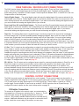
Video Transcoding - Allows composite and S-Video inputs to source the composite, S-Video and component
video outputs. Composite video will transcode to S-Video and S-Video will transcode to composite. Video
transcoding allows a single set of component video cables to be used with a video monitor.
Room Equalization (Notch Filters) - Three sweepable notch filters and variable equalization are available in
the digital domain for use in achieving the best possible room response.
Motorola
371 Processor - The latest in Motorola technology provides outstanding processing power.
Two-zone operation - One main digital & analog A/V zone, (Theater Zone) plus a separate independent
analog A/V zone for use with a second listening/viewing area (2
nd
zone).
CK1.2 Keypad Compatible - B&K’s CK1.2 Keypad easily integrates with the B&K processor/receivers for
control of the main theater zone or the second A/V Zone B.
Sleep Timer - 30 minutes to 4 hours in 30 minute increments.
5 Year Parts and Labor Warranty - For all B&K products sold through authorized dealers.
Gold Plated Connectors - Improved sound with minimum signal loss and degradation.
Internal Digitally Synthesized AM/FM Stereo tuner - Store up to 40 AM or FM stations in A/V presets.
Digital inputs/outputs - Six coaxial and five optical inputs. Two coaxial outputs (Theater zone & Second
zone) and one optical output for the Theater zone.
Analog inputs/outputs - Seven A/V inputs each with stereo audio, composite video and S-video inputs. One
assignable SACD or DVD-Audio input. One set of 7.1 line-level outputs. Three analog (record) loop outputs.
Control Outputs - Four 12 VDC @ 50 mA outputs for turning on (triggering) B&K amplifiers and controlling
external systems such as a projection screen. Up to three control outputs can be configured for IR outputs to
allow integration with a keypad or IR repeater control system.
IR inputs - Two IR inputs for keypads or external IR repeater control systems.
A/V presets - 40 preset memories allow instant recall of user settings and system configuration.
Customized Input and Preset Names - Assign custom names to presets, inputs, and the power on message.
RS-232 Control - Easy control and interface of your B&K product with other system controllers.
96/24 bit A/D and 192/24 bit capable D/A Conversion - Ultra high reproduction resolution of musical details.
96/24 Bit Processing - 96/24 bit digital data and analog source material use 96 kHz, 24 bit DSP processing
during all stereo listening modes.
Selectable Bass Management Crossover Frequency and Slope - Allows system versatility for bass adjust-
ments and management to assure superior performance from your speaker system. Shelving equalization
adjustments can be made to either end of the response frequency spectrum to further enhance the listening
room for optimal playback.
Upgradeable - Modular design allows for future A/D, D/A, DSP, and Digital Receiver upgrades. State of the
art today, state of the art tomorrow.
FEATURES
4

AUDIO / VIDEO OVERVIEW
Definitions
Sources - A source is considered any device that can be connected to the audio/video receiver or processor
and transmit a signal that can be seen or heard. Typical sources include DVD players, satellite boxes, CD
players, etc. Your receiver can provide audio from its built-in AM/FM tuner. Your receiver is designed to
accommodate a wide range of audio and video signals.
Zone - A zone is usually a room or section of the house that has speakers and/or video installed in it. Your
receiver includes a full preamp/processor for Zone A , the main theater zone, plus an additional analog audio
and video preamp for Zone B - the second zone. Two zones allow for watching a Dolby Digital movie in the
main theater while simultaneously using the built-in AM/FM tuner in the second zone.
Amplifier - An amplifier takes the output of a pre-amplifier/processor and increases its levels necessary to
drive a speaker. In a receiver the amplifier is combined into the same box with the processor. B&K employs
high current amplifiers in their receivers. These amplifiers are also available as separate components.
Speakers - A surround sound system typically uses 5 speakers located left front, center front, right front, right
surround, and left surround plus a subwoofer located anywhere in the room. With the new developments in
surround technology from companies such as Dolby Laboratories and DTS, it is now possible to improve
spatial expressions with an additional channel of information for use with a 6
th
or 7
th
surround back
speaker(s). Although best results are achieved using seven large speakers plus a subwoofer, this is not
always practical. Excellent results can be achieved using small and/or fewer speakers, as long as you go
through the setup procedures described later in the manual. Your processor includes the capability of repro-
ducing up to 7.1 channels of surround information.
A/V Preamplifier - An A/V preamplifier has the capability to select from a number of A/V sources, adjust
volume levels and route the audio to an amplifier and video to a video monitor. An A/V preamplifier requires
the use of an external power amplifier.
Surround Processor - A processor typically includes the capability to decode one or more surround formats,
and convert between digital and analog as required. Your A/V receiver includes a high quality Motorola
TM
processor capable of decoding the various audio surround formats.
Composite video vs. S-video vs. Component video - Composite video is the oldest standard for color
video. It combines the luminance (brightness or black-and-white) and chrominance (color) information onto a
single conductor. At the monitor, this composite video signal must be separated again for it’s display which
results in some degradation of the original video quality. S-video is a standard that uses separate conductors
for the luminance (Y) and chrominance (C) information resulting in better video quality. Component video is a
form of video which first became popular with the introduction of the DVD player. Most component video
signals are a variation of the red, green and blue signals that make up a television image. The simplest type,
RGB, consists of the three discrete R, G & B signals sent over three video cables. Another type consists of R-
Y, B-Y and Y (also known as YUV), that is also sent over three video cables. Y is the luminance channel, R-Y
is the red component minus the luminance information, and B-Y is the blue component minus the luminance
information. Your receiver is capable of switching composite, S-video and component video signals, and
converting between signal types. Your A/V receiver is capable of transcoding composite video and S-video to
component YUV video signals.
Transcoding - Video transcoding is the process of converting one video format to another. Video
transcoding is a new technology brought about by the need to integrate these many different video formats.
Video transcoding does not change the resolution of the original video signal and allows different video
formats to be viewed on one video monitor. Video transcoding research is being driven by the need to
integrate video technologies pertaining to computer networks, cell phone, PDAs, television and satellite. Your
A/V receiver is capable of transcoding composite video and S-video to component YUV signals.
AUDIO / VIDEO OVERVIEW
5

Analog vs. Digital Audio - This refers to the method used to place audio information on the source material
and how they are delivered to your receiver from the source. Analog signals exactly represent the sound you
will hear through a continuously varying voltage. Audio cassettes are analog recordings and are normally
delivered to your receiver over a pair of coaxial audio cables.
Digital signals closely approximate the original audio signals with a set of numbers referred to as a bitstream.
CDs and DVDs are sources of digital audio and are normally connected to your receiver through a single
coaxial or optical digital cable. There are several different bitstream formats available. The simplest format is
called Pulse Code Modulation (PCM). In PCM, the bitstream directly represents the original 2-channel audio.
In Dolby Digital and DTS (see "Audio and Surround Formats" below) bitstreams are modified using a process
called compression to squeeze more information into limited space. DTS squeezes 5.1 channels into the
space normally required for two uncompressed channels, while Dolby Digital squeezes 5.1 channels into
about ¼ the space required for two channels. Your receiver automatically detects the bitstream currently
being provided from the source and performs the required decompression and surround processing. If no
digital signal is present your receiver will automatically switch to analog processing. All sounds that you hear
from your speakers are analog. Digital signals are automatically converted to analog by your receiver before
being output to the speakers.
If analog signals exactly represent the audio, while digital signals only approximate it, why would I
want to use digital?
All analog sources add some amount of noise and distortion to the audio signal. Additional noise can be
picked up through the cables from the source to your receiver. It is impossible for the receiver to tell the differ-
ence between the desired signal and the added noise and distortion, so it reproduces both of them. The
result is increased background noise and decreased dynamic range and fidelity. Digital signals are virtually
immune to noise and distortion. The receiver can, therefore, reproduce the signal with the greatest possible
fidelity. We recommend you use digital signals whenever possible. Also Dolby Digital and DTS (see "Audio
and Surround Formats" below) work only with digital signals.
AUDIO AND SURROUND FORMATS
Your source material will be played back on your B&K processor in one of the following possible formats
described below. Each format can be used for various listening conditions.
Monaural (Mono) - Mono is the oldest format available. It contains a single, full range audio channel. Modern
recordings are seldom made in this format, however older movies and music may only be available in this
format. You may get mono from any source - digital or analog. Your receiver can produce mono in one to
seven channels depending on speaker and audio setup. Since all modern sources are stereo, the mono infor-
mation is usually replicated on both the left and right channels.
Stereo - Stereo contains two discrete, full-range front left and right audio channels. This is the most common
format for music and is also used on many movies. You may get stereo from any source - digital or analog.
Sound will normally come from the seven speaker channels, but your receiver can produce stereo in two to
seven channels, depending on speaker and audio setup.
Dolby Digital 5.1 - Dolby Digital 5.1 is a method of transmitting and storing 5.1-channel soundtracks via
digital media such as DVDs, digital cable, digital broadcast TV (DTV), and satellite transmissions. Dolby
Digital 5.1 is transmitted over the optical digital or coax digital connections. Unlike the Dolby Surround
encode/decode Pro Logic process, which sacrifices channel separation to get surround onto any stereo
soundtrack, Dolby Digital 5.1 is a discrete system that keeps the multiple channels fully separated throughout
the encoding and decoding processes. In addition to having full-range front left, center, right, left surround,
and right surround channels, Dolby Digital 5.1 soundtracks carry a sixth (“.1”) channel recorded with low-
frequency effects. For more information on Dolby Laboratories, please visit www
.dolby.com.
AUDIO / VIDEO OVERVIEW
6

Dolby Digital Surround EX - Dolby® Digital Surround EX™ provides a third surround channel on Dolby
Digital movie soundtracks. The third surround channel can be decoded at the cinema's or home viewer's
option for playback over surround speakers located behind the seating area. The left and right surround
channels are reproduced by surround speakers to the sides. To maintain compatibility, the back surround
channel is matrix-encoded onto the left and right surround channels of an otherwise conventional 5.1 mix, so
no information is lost when the film is played in conventional 5.1.
A 5.1-channel soundtrack can be played on a 5.1-speaker system. But it is not always understood that it can
also be played on a 6.1- or a 7.1-speaker system. To do this, the two surround signals on the 5.1 soundtrack
are spread across the three or four surround speakers. This distribution can be accomplished by a Dolby
Digital EX decoder, or other proprietary methods provided in home theater equipment by various manufac-
turers.
Dolby Pro Logic II - Pro Logic II brings exciting features and advanced performance for decoding the many
thousands of existing Dolby Surround programs, making them sound more like a discrete Dolby Digital 5.1-
channel version than ever before. Pro Logic II is able to decode the thousands of existing Dolby Surround
movies and TV shows already on the shelf, compatibly, and with enhanced image stability. The improvements
in decoding techniques mean that the discreteness of the sound field elements are better preserved in the
decoding process than was possible with the standard Pro Logic technology. Pro Logic II offers a music mode
to expand stereo non-matrix recordings into a five-channel layout in a way that does not diminish the subtlety
and integrity of the original stereo recordings.
Dolby Pro Logic IIx - Dolby Pro Logic IIx is a new extension of Dolby Pro Logic II technology. This highly
sophisticated algorithm processes native stereo audio signals and 5.1-channel multi-channel content to
produce 6.1 or 7.1 output channels. Dolby Pro Logic IIx expands the choice in playback system configuration
(allowing 5.1, 6.1, or 7.1 playback channels) and, when incorporated into an A/V receiver or processor such
as B&K, it allows a convenient upgrade path from a traditional 5.1-channel sound system to 7.1 output
channels. The two surround back channels are decoded into stereo.
Center width - The Center Width control allows the user to modify the amount of steering that is
applied to Center signals. As steering is reduced, the Center signal originates increasingly from the Left and
Right speakers, and is concurrently reduced in the Center speaker. The purpose of the Center Width control
is to reduce the “hard Center channel” phenomenon that sometimes results from Center signal steering of
stereo encoded soundtracks.
Panorama - The function of the Panorama mode is to create a more enveloping front surround field. It
is equally useful when applied to Dolby Pro Logic IIx processing.
Movie or Music - Surround programs are primarily movie based. Even TV dramas are essentially
mixed like movies. When programs are mixed in surround, they are monitored through the surround decoder
that will be used for playback in the cinema or home. Movie mode is the reference decoder mode for any
such surround-encoded program.
Music, on the other hand, is commonly mixed for stereo playback, and no surround monitoring is done by the
mixer. When played back through a surround decoder, the results may not always be optimal. This is
because a movie-type decoder is expecting a signal that has been deliberately surround encoded. Music
mode brings the benefits of a highly natural and balanced multichannel surround sound field to content that
was not specifically encoded for surround playback.
AUDIO / VIDEO OVERVIEW
7

DTS 5.1 (Digital Theater Systems) - DTS is a multi-channel digital audio compression format transmitted
over optical digital or coaxial digital connections. DTS is dedicated to delivering the “Ultimate Entertainment
Experience.” DTS has created a media-delivery format that makes audio tracks sound more dynamic, more
realistic and more closely matching the original than other digitally encoded soundtracks and consumer
media. Coupled with the multi-dimensional playback benefit of surround sound technology, DTS audio quality
dramatically improves and enhances content. DTS 5.1 is an ultra realistic home theater environment, it
delivers discrete channel precision plus the all-enveloping realism for which DTS is renown. For more infor-
mation on the various DTS formats, visit www
.DTSonline.com.
DTS NEO:6 - An advanced matrix decoder. It will take any two-channel source and expand it into five or six
channels, depending on the user's speaker layout. Two-channel sources include VHS tapes, broadcast televi-
sion, stereo CDs and DVDs. DTS Neo:6 provides separate, optimized modes for stereo music materials and
matrix surround motion picture soundtracks. DTS Neo:6 also decodes a center-surround channel from
Extended Surround matrix soundtracks. Music and movie filters can be applied to the NEO:6 decoder. The
differences between these two filters apply primarily to the differences in the type of soundtrack being played
back.
DTS-ES 6.1 (Extended Surround) - The Extended Surround (ES) adds a discrete back center-surround
channel to the existing 5.1-channel array. DTS-ES Discrete 6.1 is the only home format that can deliver 6.1
discrete channels. DTS-ES is fully compatible with all types of multi-channel systems. All sounds will be
heard even when played back on a system with less than 6.1 speakers
DTS Neo:6 Movie - Movie steers decoded material toward the center channel while preserving the integrity
of the stereo mix. When listening to movies using the DTS Neo:6 movie decoder with stereo TV shows or
other surround-encoded programs, there is further enhancement to soundfield directionally, which is close to
the quality of discrete 6.1-channel sound. Conventional narrow band monaural surround channel is played as
stereo with a more realistic feel and movement.
DTS Neo:6 Music - Music steers the effects into the soundfield by utilizing the surround channels for a more
spacious, 3-dimensional feeling. When listening to music using the DTS Neo:6 music decoder, stereo music
recordings are able to provide a wide and deep soundfield. DTS Neo:6 music decoder allows you to tailor the
Center Image to your own preference. The Center Image control allows the sound of the center channel to be
placed between its own speaker and the left and right front speakers.
Bass Management - Dolby Digital and DTS-ES formats may contain up to 6 full range channels plus an LFE
(Low Frequency Effects) channel. Only a system with six full-range (large) speakers plus a subwoofer can
directly reproduce these formats. However, almost all commercially available center channel speakers and
bookshelf speakers are considered small and incapable of reproducing the lowest bass frequencies without
distortion or even damage to the speaker. Many people use small speakers in the rear of their system, while
others use small speakers for all channels. Some people may choose not to use a center channel or
surround speakers at all. Use of a subwoofer is mandatory when using small speakers to reproduce low
frequencies. In order to handle any possible combination of large, small, or missing speakers, a home theater
system must contain good bass management. Your B&K receiver contains a complete bass management
system. You can use as few as two large (full range) front left and right speakers or two small front left and
right speakers. Wherever a small speaker is used, the bass management system filters low frequency infor-
mation from going to that speaker ("high pass"). This bass information is re-routed to a speaker that can
handle it, usually a subwoofer. If no subwoofer is present, it can send the low frequency and LFE to large
front or surround speakers. The bass management crossover point can be adjusted by the user according to
the types of speakers being used.
Notch Filters (Parametric Equalization)- Notch filters are used to enhance the frequency response of a
given room. The full range frequency spectrum in an ideal scenario is completely flat. This means that there
is no variation in the decibel level between any of the frequencies as you sweep up or down the frequency
range. This type of response is almost impossible to achieve. Due to the physical geometry of any given
room, the sound waves will bounce off walls, doors or windows within the room. This reflection of sound
AUDIO / VIDEO OVERVIEW
8

waves is a desirable effect to a point. Different locations in the room will have waves that collide with one
another. This collision can cause a superposition (addition or subtraction) of the audible wavelength. In
either case, these locations are referred to as nodes. If a positive node occurs in the primary listening
position, that frequency drowns out all other frequencies at that location, resulting in limited frequency
response for that location in the room. A node can occur at any frequency, however nodes are much more
prevalent in the lower frequency ranges (below 130Hz). In these lower frequencies, the wavelengths are
physically long enough that a superposition can have a more dramatic effect than frequencies at a higher
(shorter) wavelength. A notch filter provides a means by which the receiver can effectively ‘notch’ out
resonant frequencies to achieve a balanced frequency response for a given room. Once the frequency
response has been returned to its reference level, a fuller, more dynamic audio reproduction can be heard.
B&K supports three separate notch filters for the frequency range of 20 Hz to 300Hz.
DVD-Audio (also referred to as MLP) - DVD-Audio (also referred to as MLP
TM
) - Meridian
R
Lossless
Packing. MLP
TM
is a lossless compression system for high-quality linear PCM audio. For DVD-Audio MLP
TM
performs lossless compression of 1 to 6 channels of 14 to 24-bit material sampled at rates between 32kHz
and 192kHz. With lossless compression, the decompressed signal is bit-for-bit identical to the master, just
'packed' into a lower data rate which ultimately results in a reduced size to be stored on the disc. Currently,
DVD-Audio can only be delivered to your receiver via the analog 5.1 inputs. Sound will normally come from
your front left, front right, center, left surround, and right surround speakers, as well as your subwoofer, but
your processor can produce sound in one (mono) to seven channels. Dolby Pro Logic IIx is used to matrix
the surround back left and surround back right channels if a seven channel configuration is used.
SACD (Super Audio CD) - Is a new audio recording format aimed at providing higher fidelity audio reproduc-
tion than the compact disc. It was developed by Sony and Philips. The sound of SACD comes directly
from Direct Stream Digital (DSD) recording technology. SACD disks generally contain a 2-channel stereo mix.
Many also contain a 5.1 surround sound mix. DSD's simplified mechanism for recording and playback results
in a frequency response over 100kHz and a dynamic range over 120dB across the audible frequency range.
DSD increases the resolution of music by more closely following the original wave form of the music, which
results in music reproduction that is remarkably pure and faithful to the original. For additional information
concerning the technology behind SACD, visit Sony Electronics SACD.
Cinema Processing - Cinema is an exclusive set of standards and technologies that can be applied to any
B&K surround mode. In a typical movie theater the front left, right, and center speakers are located behind
the screen. The screen tends to block high frequency information. Therefore, movie soundtracks often have
boosted high frequency content to compensate for the effects of the screen. This boost can cause some
soundtracks to sound overly bright in a home theater where speakers are typically not behind a screen. B&K
cinema mode adjusts the front left, right, and center frequency response to compensate for the boost applied
for the movie theater.
High Current Amplifiers - A high-current amplifier is capable of delivering power into low impedance
speakers without going into protection and/or shutting down. Ideally, an amplifier's output power would double
every time the load presented at its output is halved. In a typical amplifier-speaker circuit, voltage and current
are delivered to a very complex load consisting of speaker drivers, resistors, inductors, and capacitors.
Voltage may be thought of as the potential to do work, and current as what actually flows to do the work.
Although basic power may be calculated by the simple multiplication of voltage and current, it is the delivery
of the power from the amplifier to the complex speaker load that accounts for why two amplifiers may have
the same power rating into identical impedances (speaker loads), but deliver a significantly different sound
quality. Some of these sound quality differences may include perceived loudness, depth, and clarity. High
quality speakers can have nominal impedances from 8 - 2 Ohms. During very loud and dynamic audio
passages, the speaker load may dip below 2 Ohms. These low impedance drops may cause a high voltage
power amplifier with limited power storage capacity to sound harsh and distorted. A high-current amplifier
operates with much less effort and typically does not have any problem with low impedance speakers. B&K
amplifiers and receivers are High Current Power amplifiers.
AUDIO / VIDEO OVERVIEW
9

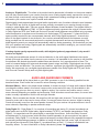
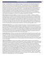
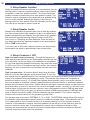
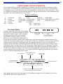
1. Headphone Jack - Headphones having a standard ¼” (6.3mm) stereo plug can be connected to the
headphone output.
2. Source Selector - Turning the selector clockwise or counterclockwise will cycle through the available
inputs. Available inputs are V1, V2, TV, DVD, CD, SAT, TAPE, FM and AM.
3. Front panel buttons -
4. Display - The receiver display contains a 16 character display. It will display current status of the receiver
and any changes being performed.
5. Main power switch - Removes all power to the receiver. Normal operation of the receiver requires the
power switch to remain on. Use the ON/STANDBY button for daily on and off of the receiver. ON/STANDBY
places the unit in standby mode that allows turning back on with the remote control. Only turn the receiver off
with the main power switch when not using the receiver for an extended period of time.
6. Volume control - Turning the volume control clockwise increases the volume level, counterclockwise
decreases the volume level. The volume knob is also used to change other receiver settings.
FRONT PANEL DESCRIPTION
10
AVR507 S2 Receiver
DVD DTS-ES MOV 7
B&K COMPONENTS, LTD.
ON / STANDBY PRESET
ENTER
MODE MENUDOWN UP
MASTER
POWER
AUDIO / VIDEO RECEIVER
AVR507
S
2
1
2
3 4 5 6
ON/STANDBY
Toggles the receiver in and out of standby mode, (ON or OFF).
PRESET
Cycles through audio presets for instant preset recall.
ENTER
Confirm Selection. Presets, menu options, unit status.
DOWN & UP
Steps through audio options or menu selections when in the menu system.
Allows AM/FM tune - (down) or tune + (up).
MODE
Steps through audio modes
MENU
Enters into and out of the menu system.

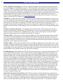
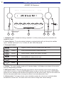
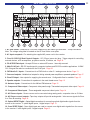
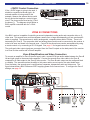
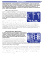
1. AC fuse holder - Holds the AC Line fuse. Replace only with same type and value - 12amp Slow Blow.
Note: The voltage rating label is located on the AC fuse holder cover plate.
2. AC input receptacle - For attaching the supplied AC power cord to the receiver.
3. Four 10-12VDC @ 50mA Control Outputs - 1/8" (3.5mm) mono mini plug. Trigger outputs for controlling
external devices, such as amplifiers, projection screens, IR emitter, etc. Page 18.
4. ZA & ZB IR Data Input - Accepts IR from an external IR source. Internally summed.
5. Main RJ-45 jack - RS-232 input/output for computer interface and RS-232 controller applications. A B&K
CK1.2 keypad can also be connected to the RJ-45 jack. Page 36.
6. DVD-Audio 5.1 inputs - Connections for a DVD-Audio or other 5.1 analog source device. Page 13.
7. Surround outputs - Variable level outputs for driving external power amplifiers or powered speakers. Page 17.
8. Zone B Output - Line outputs for supplying the second zone. Configurable fixed or variable. Page 19.
9. Speaker outputs - Connections for speakers in the main theater zone. Page 15.
10. Antenna inputs - Connections for the AM and FM antennas. Page 21.
11. Component Video output - Component video pass through. Transcoded component video output. Page 14.
12. Component Video inputs - Three assignable component video inputs. Page 14.
13. A/V Source inputs - Seven sources can be connected using analog audio, composite video or S-Video.
14. A/V Source record outputs - Tape loop outputs will provide analog audio / video source signals for Zone
A or Zone B recording. Page 18.
15. Optical SPDIF Digital - Optical digital connections for connecting optical digital audio signals from the
source to the receiver. 5 optical digital inputs, 1 digital output. Page 13.
16. Coax SPDIF Digital - Coax digital inputs are used to connect coax digital audio signals from the source
to the receiver. 6 coax digital inputs, 2 digital outputs. Page 13.
BACK PANEL DESCRIPTION
11
Audio/Video Systems Hand-Made in the U.S.A.
FRONTSURRND
SUB CENTER
+
EXPANSION
SERIAL #
AC LINE
IN 1 IN 2 IN 3V1V2TVDVDCDSATTAPETAPE
V1
ZB/V2
DVD
INPUT
A/V SOURCE OUTPUTS A/V SOURCE INPUTS COMPONENT VIDEO
www.bkcomp.com
AM FM
ANTENNA
ZONE A ZONE B
OUTPUTS
ZONE BFRONTSURRND S BACK
CENTERSUB
SURROUND OUTPUTS
OPTICAL S/PDIF DIGITALCOAX S/PDIF DIGITAL
OUT SAT CD DVD V2 V1
V1V2TVZA OUT
ZB OUT SAT CD DVD
CONTROL OUT IR INPUT
ZONE A
IEEE
1394
12VDC
50 mA
21
34
POSITIVE
NEGATIVE
POSITIVE
NEGATIVE
POSITIVE
NEGATIVE
POSITIVE
NEGATIVE
POSITIVE
NEGATIVE
POSITIVE
NEGATIVE
POSITIVE
NEGATIVE
SURROUND LEFT FRONT LEFTCENTER FRONT RIGHTSURROUND RIGHT SURROUND BACK RIGHTSURROUND BACK LEFT
BK&
SB
IMPLY ETTER!
FUSE
CAUTION: FOR CONTINUED
PROTECTION AGAINST RISK
OF FIRE REPLACE ONLY WITH
SAMETYPEANDVALUEFUSE
OUTPUT
IR INPUT
ZONE B
AUDIO
RS-232
PORT
CAUTION
RISK OF ELECTRIC
SHOCK DO NOT OPEN
5
678
4
21
910
1112
13
14
1516
3

QUICK START CONSIDERATIONS
Your B&K receiver is pre-programmed for ease of operation right out of the box. In general, there is minimal
setup required to start listening to your new receiver. To quickly setup and begin operating your receiver,
follow these quick steps:
11
Start with all AC power cords unplugged from their designated AC outlet.
2 From each source device, connect the A/V cables to the appropriate A/V SOURCE INPUTS on the
receiver’s back panel.
3 Connect the appropriate speakers to the receiver.
4 Connect the appropriate video cables from the receiver’s video OUTPUTS to the video monitor’s
input(s).
5 Plug each AC power cord into its designated AC outlet.
6 Turn on the main power switch on the front of each unit. On the receiver, press the ON/STANDBY
button on the front panel, or the ON button of the remote. Turn on all A/V sources.
7 Select a source with the SR10.1 remote control or front panel source control of the receiver.
8 For use with a component video monitor, please see Setup Inputs page 30, Component Video
Assignment.
The rest of this manual will describe in detail the many aspects of your new receiver. Some additional instal-
lation considerations should be noted as follows:
••
It is important that your electronic equipment has proper ventilation. Failure to ventilate your receiver
could result in erratic operation and possible failure caused by overheating. A minimum of 3” clearance
should be maintained above the receiver. Do not place items directly on top of the receiver.
Do not place flammable items on, around or near the A/V equipment (Curtains, paper, etc.).
••
B&K supports various software programs that are able to aide in the setup process of the
receiver/preamplifier, SR10.1 remote and CK1.2 Keypad. This software is available online at B&K’s
website at www
.bkcomp.com or by request from B&K’s customer service. The setup software is easy
to use and is intended to simplify the setup process of your new B&K products.
••
Configure a system diagram of all components that are to be connected into the system. The receiver
has seven sets of inputs. Even though the back panel is labeled for specific sources, in most cases it
is possible to connect any source to any input. For example, if you have a satellite receiver you can
connect it to the V2 input and it will work the same way as connecting it to the SAT input. Select V2
instead of SAT. The source name that will appear on the receiver’s front panel and on the remote or
keypad can be relabeled to match the source equipment that is being used.
••
Determine the type of cable that is needed. Keep in mind that the quality of the cabling that is used
can make a difference in the overall audio and video quality. Try to keep interconnecting cable runs as
short as possible. When routing cables between equipment, be sure to keep AC cables separate from
audio cables. It is a good idea to bundle like cables together to keep interference (noise) to a
minimum.
••
Decide on what types of audio and video signals are going to be used in the system. Determine the
length of the cable for each component's connection and how it should be routed. It is a good idea to
label each cable with a name or number at both ends when allocating each cable. Have all the cables
you need before you begin the installation because it is inconvenient to run to the store when you are
excited to hear what the system will sound like.
••
Plan enough cable length and space to allow future access to the back panel.
••
For best tuner reception, make sure the antenna is several feet away from the receiver and any other
equipment that may produce high frequency interference such as personal computers, CD players,
halogen lamps, etc.
••
For best performance it is recommended that a dedicated AC power line be used for the best
audio reproduction. If the equipment is installed in a rack, be sure to insulate the equipment from the
rack itself.
QUICK START
12

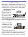
SOURCE CONNECTIONS
Your receiver supports several A/V input and output formats. In most cases only one audio and one video
connection is needed for each source device. Shown below are the available options:
Analog audio (Stereo): left and right. Composite video: coaxial (Yellow RCA).
Digital audio: either coaxial or optical. Super-Video: S-Video.
DVD-Audio & Super Audio CD (SACD): Analog 5.1 Component video: Red, Green & Blue.
Connect an audio / video source to the surround receiver. Use the diagrams that follow as a guide for each of
the seven source inputs. For analog audio connections, use the left and right (white and red) RCA connec-
tions. For composite video, use the yellow RCA connections. For S-video use the S-video connections. For
digital audio, use EITHER the coaxial digital connection (orange RCA) or the optical digital connection per
each source. The order of audio signal precedence per each input is: Optical Digital > Coax Digital > Analog
left and right. For component video, use the red, green and blue RCA component connections. See
Video Monitor Connection page 14 for details on connecting a video monitor.
If the second zone of the surround receiver or the record loop outputs are going to be used, the analog audio
and composite video and/or S-video signals must
be connected to the surround receiver. The receiver will
neither process nor convert digital audio or component video for use in the the second zone.
Source Connection Diagram
Coaxial Digital Connection Optical Digital Connection
SACD or DVD-Audio Connection
DVD-Audio or SACD is a discrete 5.1 channel analog audio mode. If the source gear contains connections
for DVD-Audio or SACD, use the DVD-Audio input connections on the back panel of the surround receiver.
The DVD-Audio input can be assigned to any source input except Tape (see Setup Inputs page 29). Be sure
to maintain the discrete channel connections.
Each channel is labeled appropriately
according to the speaker location in the
room.
Many times, DVD-Audio players have
multiple configuration options. The receiver
does not supply bass or delay management
for the DVD-Audio/SACD input. You should
adjust your player's bass and delay manage-
ment to match that of the receiver.
13
OR
HARDWARE CONNECTIONS

VIDEO MONITOR CONNECTION
There are many types of video monitors that can be used with your B&K system. Some popular video
monitors are televisions, plasma screens, LCD screens and projectors. The B&K A/V receiver has video and
audio switching capability. The system source devices should be connected to the B&K receiver for both
audio and video. One set of video cables may be connected from the B&K receiver's component video OUT
to the video monitor. The B&K video processor features video transcoding. Video transcoding allows multiple
video formats to be combined onto one. Transcoding will not change the resolution of the image. Specifically
composite video is transcoded to S-video (S) and component video. S-video is transcoded to composite video
and component video. Component video is not transcoded. The On Screen Setup Menu is available in all
three video formats. B&K recommends using the component video inputs for High Definition source signals.
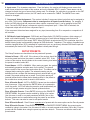
Component Video Monitor Connection
The B&K surround receiver provides three
sets of component video inputs and one
component video output. Since there are seven
A/V inputs and only three component inputs,
the receiver must be configured for which
component input to use with the selected A/V
source. For example, component Input 1 is
assigned to DVD, whenever DVD is selected, the
component output will come from component
Input 1. Composite to S or S to composite
transcoding will continue to function for the
DVD input. Component video is not transcoded to
composite or S. If no component assignment is made to a particular input, the component output will be
transcoded from the appropriate composite or S-video input. The receiver automatically detects the presence
of composite or S-Video. No user assignment is necessary.
IMPORTANT: By factory default, all Component Video inputs are unassigned. For use with component
video sources, HDTV receivers or progressive scan DVD players, each COMPONENT VIDEO must be
assigned for use with an A/V SOURCE INPUT (page 29) to operate correctly.
S-Video Monitor Connection
Each of the seven A/V inputs are provided with
an S-video input. There is an S-video output
for each zone of the surround receiver. Zone A
output will pass through S-Video or transcode
from composite video. Zone B S-video output will
provide output only from S-video inputs - there is
no transcoding for Zone B. The Line Output
section provides S-video outputs for recording
devices in Zone A or Zone B. S-Video record
outputs provide output only from S-video inputs -
there is no video transcoding for the record
outputs.
Composite Video Monitor Connection
Each of the seven A/V inputs are provided with a composite RCA video input (yellow). There is a composite
RCA video output for each of the zones of the surround receiver. Zone A video output will pass composite
video through or transcode from S-video. Zone B composite video output will provide output only from
composite video inputs - there is no transcoding of video in Zone B. The Line Output section provides
composite outputs for recording devices used in Zone A or Zone B. The composite video record outputs
provide output only from composite video inputs - there is no video transcoding with the record outputs.
HARDWARE CONNECTIONS
14

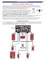
SURROUND SPEAKER CONNECTIONS
Your B&K receiver has two types of surround outputs: speaker outputs and preamplifier RCA outputs.
Speaker outputs connect from the receiver directly to the speakers in the system using a five-way binding
post. The RCA outputs are used to connect external amplifiers and/or the
subwoofer to the system. RCA connections are described on page 17.
Five-way binding posts are provided for direct speaker connection, one pair for
each channel. Up to 4 gauge speaker wire can be terminated directly into the
bottom of the binding post. Additionally each binding post is designed to
accept a banana-type plug or a spade plug connector. They are color coded
for easy identification. OBSERVE POLARITY WHEN CONNECTING
SPEAKERS! The positive (red) post should always be connected to the speaker's positive (red) jack. The
negative (black) post should always be connected to the speaker's negative (black) jack.
For best acoustic results, be sure to set up speakers using the speaker setup menu. To Setup System
Speakers see page 25. Note: The AVR505 Series2 has five surround speaker output channels.
7.1 Speaker Connection
To connect speakers using a 7.1 or 7.0 speaker configuration see the connection diagram below. The point
one (.1) indicates whether or not the system will use a subwoofer. If a subwoofer is used, connect an RCA
type coaxial cable from the Zone A SUB OUT to the subwoofer.
HARDWARE CONNECTIONS
15
Spade Connector
Banana Jack

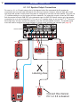
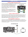
6.1 / 5.1 Speaker Output Connections
For use in a 6.1 or 6.0 audio setup, refer to the diagram below. We recommend the 6th speaker be
connected to the surround back left channel of the surround receiver. However, either the back left or back
right output will operate correctly when the system is configured for use with one back speaker. The point one
(.1) indicates whether or not the system will use a subwoofer. If a subwoofer is used, connect an RCA cable
from the receiver’s Zone A SUB OUT to the subwoofer input. An AVR 505 Series2 receiver only has speaker
connections for up to a five channels (5.1). For use in a 5.1 speaker setup, do not use the 6
th
or 7
th
surround
back channel(s) and only connect five speakers using the surround speaker channels. The speaker setup
menu will used to configure the internal software for proper audio selection and operation (see page 25).
HARDWARE CONNECTIONS
16
Audio/Video Systems Hand-Made in the U.S.A .
FRONTSURRND
SUB CENTER
+
EXPANSION
SERIAL #
AC LINE
IN 1 IN 2 IN 3V1V2TVDVDCDSATTAPETAPE
V1
ZB/V2
DVD
INPUT
A/V SOURCE OUTPUTS A/V SOURCE INPUTS COMPONENT VIDEO
www.bkcomp.com
AM FM
ANTENNA
ZONE A ZONE B
OUTPUTS
ZONE BFRONTSURRND S BACK
CENTERSUB
SURROUND OUTPUTS
OPTICAL S/PDIF DIGITALCOAX S/PDIF DIGITAL
OUT SAT CD DVD V2 V1
V1V2TVZA OUT
ZB OUT SAT CD DVD
CONTROL OUT IR INPUT
ZONE A
IEEE
1394
12VDC
50 mA
21
34
POSITIVE
NEGATIVE
POSITIVE
NEGATIVE
POSITIVE
NEGATIVE
POSITIVE
NEGATIVE
POSITIVE
NEGATIVE
POSITIVE
NEGATIVE
POSITIVE
NEGATIVE
SURROUND LEFT FRONT LEFTCENTER FRONT RIGHTSURROUND RIGHT SURROUND BACK RIGHTSURROUNDBACKLEFT
BK
&
SB
IMPLY ETTER!
FUSE
CAUTION: FOR CONTINUED
PROTECTION AGAINST RISK
OF FIRE REPLACE ONLY WITH
SAMETYPEANDVALUEFUSE
OUTPUT
IR INPUT
ZONE B
AUDIO
RS-232
PORT
CAUTION
RISK OF ELECTRIC
SHOCK DO NOT OPEN
X
Surround Left
Surround Right
Listening Area
Center
NEG (-)
POS (+)
NEG (-)
POS (+)
NEG (-)
POS (+)
NEG (-)
POS (+)
NEG (-)
POS (+)
Front Left
AVR507 Series2
Front Right
Surround
Back L
NEG (-)
POS (+)
AC Line
Subwoofer
IN
OUT
SUBWOOFER I/O
ON
OFF
I
O
P
B
P
B
Connect this channel
if 6.1 or 6.0 is desired

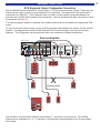
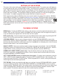
RCA Surround Output / Subwoofer Connection
Both the AVR505 Series2 and AVR507 Series2 supply 7.1 RCA surround processor outputs. These surround
outputs can be used to connect external amplifiers or the subwoofer. The subwoofer for the system will be
connected to the SUB OUT. If the subwoofer does not contain its own amplifier (powered subwoofer) an
external power amplifier will be needed for the subwoofer. Once the subwoofer has been connected, to setup
the subwoofer see page 25.
If an external speaker amplifier is supplied, each speaker channel can be connected to the appropriate RCA
output.
To use the surround outputs, simply connect an RCA type audio cable between the receiver and the external
amplifier. The diagram below shows a B&K Reference 200.2 Series2 amplifying the front left and right
speakers. This configuration can be performed without any hardware or software modifications.
External Amplifier
Note: All B&K receivers contain software for processing 7.1 channels of surround audio. The AVR505
Series2 can be expanded to 6.1 or 7.1 operation by connecting an external amplifier to the Surround Back
RCA outputs
HARDWARE CONNECTIONS
17
X
Surround Left
Surround Right
Listening Area
NEG (-)
POS (+)
NEG (-)
POS (+)
NEG (-)
POS (+)
NEG (-)
POS (+)
NEG (-)
POS (+)
Audio/Video Systems Hand-Made in the U.S.A.
FRONTSURRND
SUB CENTER
+
EXPANSION
SERIAL #
AC LINE
IN 1 IN 2 IN 3V1V2TVDVDCDSATTAPETAPE
V1
ZB/V2
DVD
INPUT
A/V SOURCE OUTPUTS A/V SOURCE INPUTS COMPONENT VIDEO
www.bkcomp.com
AM FM
ANTENNA
ZONE A ZONE B
OUTPUTS
ZONE BFRONTSURRND S BACK
CENTERSUB
SURROUND OUTPUTS
OPTICAL S/PDIF DIGITALCOAX S/PDIF DIGITAL
OUT SAT CD DVD V2 V1
V1V2TVZA OUT
ZB OUT SAT CD DVD
CONTROL OUT IRINPUT
ZONE A
IEEE
1394
12VDC
50mA
21
34
POSITIVE
NEGATIVE
POSITIVE
NEGATIVE
POSITIVE
NEGATIVE
POSITIVE
NEGATIVE
POSITIVE
NEGATIVE
SURROUND LEFT FRONT LEFTCENTER FRONT RIGHTSURROUND RIGHT
BK
&
SB
IMPLY ETTER!
FUSE
CAUTION: FOR CONTINUED
PROTECTION AGAINST RISK
OF FIRE REPLACE ONLY WITH
SAMETYPEANDVALUEFUSE
OUTPUT
IR INPUT
ZONE B
AUDIO
RS-232
PORT
CAUTION
RISKOF ELECTRIC
SHOCKDO NOT OPEN
AVR507 Series2
Reference 200.2 S2
F
U
S
E
F
U
S
E
F
U
S
E
F
U
S
E
F
U
S
E
F
U
S
E
F
U
S
E
F
U
S
E
F
U
S
E
F
U
S
E
F
U
S
E
F
U
S
E
FUSE
CAUTION: FOR CONTINUED
PROTECTION AGAINST RISK
OF FIRE REPLACE ONLY WITH
SAME TYPE AND RATING.
CHANNEL 2 OUTPUTCHANNEL 1 OUTPUT
CHANNEL 1 INPUT CHANNEL 2 INPUT
CTRL
OUT
12VDC
200mA
CONTROL IN ALLOWS AMPLIFIER
OPERATION WHEN A 5-24V SIGNAL
IS APPLIED
W
ITH A 3.5mm
MINI JACK
XLR (BALANCED)
RCA (UNBALANCED)
XLR (BALANCED)
RCA (UNBALANCED)
RCA INPUT
XLR INPUT
RCA INPUT
BK
&
SBIMPLY ETTER!
SERIAL #
CTRL
IN
RISK OF ELECTRICSHOCK
DO NOT OPEN
RISK OF ELECTRICSHOCK
DO
NOT OPEN
AC LINE
POSITIVE
NEGATIVE
POSITIVE
NEGATIVE
CONTROL I/O
www.bkcomp.com
High Performance
Audio/Video Systems
Hand-Made in the U.S.A.
+12VLOW
P
OWER
+12V
LOW
POWER
RING
TIP
GROUND
SLEEVE
+12V
C
TRLENABLE
+12V
CTRL
ENABLE
XLR INPUT
Y
Y
P
B
P
B
Front Left
AC Line
Subwoofer
IN
OUT
SUBWOOFER I/O
ON
OFF
I
O
Front Right
Center
Surround
Back R
Surround
Back L
NEG (-)
POS (+)
NEG (-)
POS (+)
P
B
P
B
POSITIVE
NEGATIVE
POSITIVE
NEGATIVE
SURROUND BACK LEFT SURROUND BACK RIGHT

PASS THROUGH / RECORD LOOP CONNECTIONS
The B&K receiver has a few options for record/pass through outputs. There is a Zone A optical digital
output, a Zone A coaxial digital output and a Zone B coaxial digital output. The B&K receiver provides
three analog audio, composite & S-video outputs. These outputs are labeled TAPE, V1 and Z2/V2 in the Line
Outputs section of the back panel.
Optical Digital Output - The optical digital output will output the digital signal of the source selected in the
main theater zone (Zone A). Coaxial digital inputs are converted to optical. You need only connect one or the
other. Analog inputs are not converted to digital output. If you wish to record both analog and digital sources
you must connect both analog and digital inputs to your recorder.
Zone A and Zone B Coaxial Digital Outputs - The Zone A and Zone B coaxial digital outputs will output the
digital signal of the source selected in the corresponding zone. Optical digital inputs are converted to coaxial.
You need only connect one or the other. Analog inputs are not converted to digital output. If you wish to
record both analog and digital sources you must connect both analog and digital to your recorder.
Tape Out - The analog Tape output is a pass through / record loop output for the source that is selected in
the main theater zone. To prevent possible speaker damaging feedback, tape out will not output the TAPE
source input. Digital audio is not converted to analog audio on the Tape output. You must connect analog
audio to the A/V inputs if you want to make analog recordings from the input device. Only LtRt mode will
downmix a digital bitstream into left and right analog. Video is not transcoded on the Tape output. If you have
a composite recorder you must connect composite from each A/V source you wish to record. If you have a S-
video recorder you must connect S-video from each A/V source you wish to record.
V1 Out - The V1 output can be configured as an output for a second recording device in Zone A or as a Zone
A line output to connect a second video monitor and/or audio amplifier. As a record output, V1 will output the
analog audio and video from the selected input in Zone A except when V1 is selected. This prevents
feedback through the recording device which could damage your speakers. As a line output V1 will output the
analog audio and video from whatever input is selected in Zone A. LtRt mode will downmix a digital bitstream
to left and right. Record/Line settings also apply to the Zone A optical and coaxial digital outputs. Similar to
the Tape output, digital audio is not converted to analog on the V1 output. Video is also not transcoded on the
V1 output. To configure the V1 output see page 33.
ZB / V2 Out - The V2 output can be configured as an output for a second recording device in Zone B or as a
Zone B line output to connect a second video monitor and/or audio amplifier. As a record output, V2 will
output the analog audio and video from the selected input in Zone B except when V2 is selected. This
prevents feedback through the recording device which could damage your speakers. As a line output V2 will
output the analog audio and video from whatever input is selected in Zone B. Record/Line settings also apply
to the Zone B optical and coaxial digital outputs. As with the Tape output, digital audio is not converted to
analog on the V2 output. Nor is video transcoded on the V2 output. To configure the V2 output, see page 38.
CONTROL OUTPUT CONNECTIONS
The B&K surround receiver is supplied with four control outputs. These control outputs can be used for a
variety of applications that require a 12 volt control or an IR output (pass through). The control outputs use a
1/8” (3.5mm) mono mini plug. Each output is 10-12VDC @ 50 mA. Control output 1 is strictly a +12VDC
control trigger. Control outputs 2-4 can be set up as either +12VDC controls or as an IR pass through. To
configure the control outputs, see the control setup section on page 35.
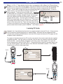
IR Emitter Connection
To connect an IR emitter to the control output, one end should be
terminated into a 3.5mm mono mini plug, tip (+), sleeve (-). The IR
output will pass through IR signals received by the surround
receiver. Only industry standard 38kHz IR can be used with the IR
outputs. Additional resistance may be required in series with the IR
emitter, check the current rating of the emitter you are using.
HARDWARE CONNECTIONS
18
L
Audio/Video Systems Hand-Made in the U.S.A.
FRONTSURRND
SUB CENTER
+
IN 1 IN 2 IN 3V1V2TVDVDCDSATTAPETAPE
V1
ZB/V2
DVD
INPUT
A/V SOURCE OUTPUTS A/V SOURCE INPUTS COMPONENT VIDEO
AM FM
ANTENNA
ZONE A ZONE B
OUTPUTS
ZONE BFRONTSURRND S BACK
CENTERSUB
SURROUND OUTPUTS
OPTICAL S/PDIF DIGITALCOAX S/PDIF DIGITAL
OUT SAT CD DVD V2 V1
V1V2TVZA OUT
ZB OUT SAT CD DVD
CONTROL OUT IR INPUT
ZONE A
IEEE
1394
12VDC
50 mA
21
34
OUTPUT
IR INPUT
ZONE B
AUDIO
RS-232
PORT
PLAY 8:33
PLAY 8:33
Page is loading ...
Page is loading ...
Page is loading ...
Page is loading ...
Page is loading ...
Page is loading ...
Page is loading ...
Page is loading ...
Page is loading ...
Page is loading ...
Page is loading ...
Page is loading ...
Page is loading ...
Page is loading ...
Page is loading ...
Page is loading ...
Page is loading ...
Page is loading ...
Page is loading ...
Page is loading ...
Page is loading ...
Page is loading ...
Page is loading ...
Page is loading ...
Page is loading ...
Page is loading ...
Page is loading ...
Page is loading ...
Page is loading ...
Page is loading ...
Page is loading ...
Page is loading ...
Page is loading ...
Page is loading ...
Page is loading ...
Page is loading ...
Page is loading ...
Page is loading ...
Page is loading ...
Page is loading ...
Page is loading ...
Page is loading ...
Page is loading ...
Page is loading ...
-
 1
1
-
 2
2
-
 3
3
-
 4
4
-
 5
5
-
 6
6
-
 7
7
-
 8
8
-
 9
9
-
 10
10
-
 11
11
-
 12
12
-
 13
13
-
 14
14
-
 15
15
-
 16
16
-
 17
17
-
 18
18
-
 19
19
-
 20
20
-
 21
21
-
 22
22
-
 23
23
-
 24
24
-
 25
25
-
 26
26
-
 27
27
-
 28
28
-
 29
29
-
 30
30
-
 31
31
-
 32
32
-
 33
33
-
 34
34
-
 35
35
-
 36
36
-
 37
37
-
 38
38
-
 39
39
-
 40
40
-
 41
41
-
 42
42
-
 43
43
-
 44
44
-
 45
45
-
 46
46
-
 47
47
-
 48
48
-
 49
49
-
 50
50
-
 51
51
-
 52
52
-
 53
53
-
 54
54
-
 55
55
-
 56
56
-
 57
57
-
 58
58
-
 59
59
-
 60
60
-
 61
61
-
 62
62
-
 63
63
-
 64
64


Ask a question and I''ll find the answer in the document
Finding information in a document is now easier with AI
Related papers
Other documents
-
König SAT-MS512-KN10 Datasheet
-
Bryston 2 Way Owner's manual
-
Antec Rockus 3D 2.1 User manual
-
Cary Audio Design Cinema 11 User manual
-
MTX Audio SW2 User manual
-
JBL AVR 580 User manual
-
 PRO SIGNAL PSG3460 Operating instructions
-
 Legend Audio ATP 7500 User manual
-
DB Drive E5 HLC6 Owner's manual
-
 Accent Acoustics HT-3200BGW User manual


