Instructions
© Danfoss | DCS (CC) | 2018.11 | 5
FRCC.PI.061.A1.02
1 – Introduction
This instruction applies to fan-cooled condensing
units for the refrigerant R290 (or similar
inammable gases).
During service only the refrigerant type stated on
the condensing unit must be used.
2 – Versions
Version N0: for solder connection, has a nitrogen
holding charge and is designed for use in
refrigeration systems with capillary tube.
Version A09: for solder connection, has a
helium/dry air holding charge and is designed
for use in refrigeration systems with tubes for
pressostats and premounted bracket. This version
has premounted wired electrical box and one
schrader port.
Version A10: for solder connection, has a
nitrogen holding charge and is designed for
use in refrigeration systems with premounted
pressostats (HP and LP switch). This version has
premounted wired electrical box, combo lter
drier/receiver and one schrader port.
Version A11: for solder connection, has a
nitrogen holding charge and is designed for use
in refrigeration systems with capillary tube. This
version has premounted wired electrical box and
one schrader port.
3 – Refrigerant charging
With regard to evacuation and charging an
condensing unit is to be treated as a compressor.
Refrigerant charging must take place from
a charging board not contaminated with
refrigerants containing chlorine. No valves or are
connections of any kind must be used.
The condensing unit must be hermetically sealed,
i.e. all connections must be soldered. After
charging all solderings/connections are to be
checked for leaks with a leak detector.
Keep away ammables from the condensing
unit.
4 – Installation
• Install the condensing unit in the foreseen
location.
• Prepare the tube connections from the
evaporator.
• Use a drier with molecular sieves suitable
for R290 (for versions N0, A09, A11).
• Use only dry and clean components and
avoid moisture entering the system.
• The system components must not contain any
chlorine, mineral oil or other oily substances.
5 – Electrical connections
Fig. 1 (relay) / Fig. 2 (relay) / Fig. 3 (PTC):
1A: Main winding
1B: Start winding
1C: Start relay
1D: Winding protector (Internal)
1E: Start capacitor
1F: Bleeder resistor
1G: Run capacitor
1H: Thermostat or Pressure control
1J: Fan
1K: Pressostat (HP/LP)
1L: PTC
Fig. 5. Wiring diagram for the series NB.
Fig. 6. Wiring diagram for the series NL, NB, NX.
Fig. 7. Wiring diagram for the series NS.
Fit the terminal board cover.
Pressure switches (A10 version is premounted
with HP/LP pressostats) and thermostats must
also be mounted in an IP64 or higher classied
box. Keep away ammables from the electrical
equipment.
6 – Safety
• Disconnect the main power supply before
service or repair.
• All connections at installation location must
conrm with standard NFC15-100 in france or
local and national standards/codes enforce in
the country.
• Follow the information stated as per
EN/IEC 6024/60335-2-89.
7 – Declaration of conformity
• All our condensing units are complied with
low voltage directive 2014/35/EU and must be
incorporated during installation.
•
Low Voltage Directive 2014/35/EU
EN 60335-1:2012 + A11:2014- Household and
similar electrical appliances-Safety-Part 1:
General requirements-for all above mentioned
condensing units with compressor platforms NL,
NP, NX, NS, NT, SC, NL and NB.
• Eco-design DIRECTIVE 2009/125/
EC, establishing a framework for the setting
of Eco-design requirements for energy-related
products
• REGULATION (EU) 2015/1095,implementing
Eco-design Directive 2009/125/EC with regard
to Eco-design requirements for professional
refrigerated storage cabinets, blast cabinets,
condensing units and process Chiller.
• Condensing unit measurements are made
according to standard “EN 13771-2:2007”
– Compressor and condensing units for
refrigeration-performance testing and test
methods- part 2: Condensing units
• The following approvals must be obtained
through authorised institutes like Nemko,
Demko, BEAB, LCJE, etc. Among others EN 60
335-2-24, IEC 335-2-89, IEC 79-15.
8 – Maximum refrigerant charges R290
units with and without receiver
• The maximum charging amount must not
exceed 150 g.
• It is recommended to charge only the amount
necessary for the operation of the refrigeration
system.
•
The charging amount must be adapted to suit each
system type.
•
The condensing temperature must not exceed 55°C
(N0 versions), 60°C (A09, A10, A11 versions) for
stationary operation and 65°C for peak load.
9 – Cold start
The compressor must be allowed to assume a
temperature higher than 10°C before it is started
for the rst time. This will prevent possible start
problems caused by too high oil viscosity.
At lower temperatures some tripping of the
winding protector may be expected until the
viscosity of the oil becomes reduced.
10 – Winding protector
The compressors have a built-in winding
protector. If the winding protector cuts out
whilethe compressor is cold it may take approx. 5
minutes for the protector to reset. If the winding
protector cuts out while the compressor is hot
(compressor housing above 80°C) up to 45
minutes may pass before the protector resets.
The winding temperature must never exceed
130°C.
Checking the winding protector
In the event of compressor failure a check must
be made by resistance measurement directly on
the current lead-in to nd out whether the fault
is due to motor damage or simply a winding
protector trip.
Location of the winding protector in the
electrical circuit.
1A: Main winding
1B: Start winding
1D: Winding protector
If resistance measuring or a test lamp shows
that there is a connection through the motor
windings from point M to point S, but a broken
circuit between points M and C or S and C, this
indicates that the winding protector has cut out.
Therefore, wait for the protector to reset.
12 – Service instructions
When emptying a defective system the
refrigerant must be collected without mixing in
other refrigerants.
Evacuation must take place until a vacuum of
1 mbar or lower is reached. Blow through the
refrigeration system with dry nitrogen.
The drier must always be replaced when a system
is opened.
Service on these installations must only be done
by expert installers with thorough knowledge of
inammable gases like e.g. propane.
See also Installation .
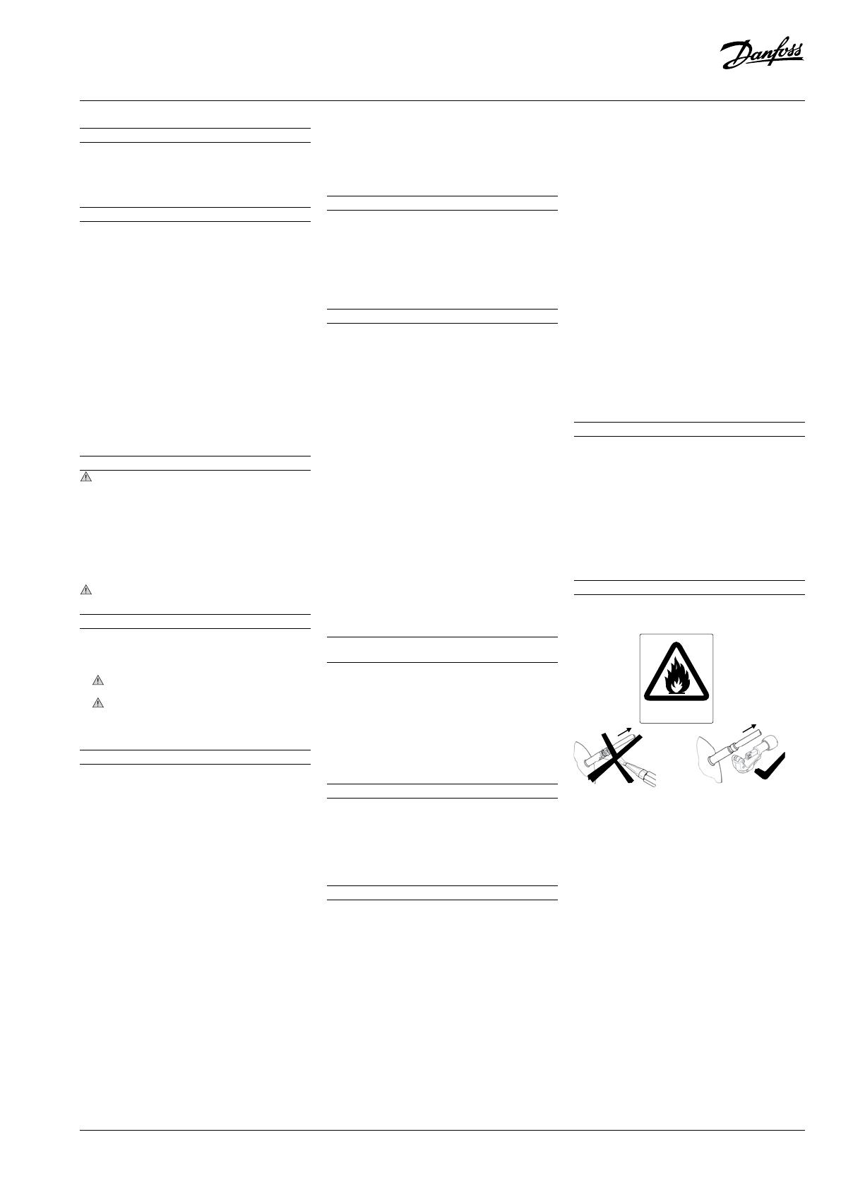
13 – Warnings
For tube connections
!
8545
4-2218
R290


