KitchenAid KRSC700HBS Owner's manual

Category
Fridges
Type
Owner's manual
W11484052A
SIDE-BY-SIDE REFRIGERATOR OWNER’S MANUAL
MANUEL D’UTILISATION DU RÉFRIGÉRATEUR CÔTE
À CÔTE
Table of Contents/Table des matières
REFRIGERATOR SAFETY.................................................2
Refrigerator Safety .........................................................2
MAINTENANCE AND CARE ..............................................3
Cleaning ......................................................................3
Lights ..........................................................................3
Freezer Shelf (number varies by model)..............................5
Vacation and Moving Care ...............................................5
INSTALLATION INSTRUCTIONS ........................................5
Unpack the Refrigerator ..................................................5
Location Requirements ...................................................6
Electrical Requirements ..................................................8
Water Supply Requirements.............................................9
Connect Water Supply ....................................................9
Complete the Installation ............................................... 11
Install Air Filter (on some models).................................... 11
Install Produce Preserver (on some models) ...................... 12
REFRIGERATOR FEATURES........................................... 13
Convertible Drawer Temperature Control (on some
models) ..................................................................... 13
Crisper Humidity Control (on some models) ....................... 13
Dual Evaporator (on some models).................................. 13
Water and Ice Dispensers .............................................. 13
Ice Maker and Storage Bin............................................. 13
Water Filtration System ................................................. 15
DOOR REMOVAL AND LEVELING STYLE 1....................... 17
Door Instructions ......................................................... 17
Install and Remove Door Handles ................................... 17
Remove Doors and Hinges ............................................ 18
Replace Doors and Hinges ............................................ 20
Door Closing and Alignment........................................... 21
DOOR REMOVAL AND LEVELING STYLE 2....................... 22
Door Instructions ......................................................... 22
Install and Remove Door Handles ................................... 22
Remove Doors and Hinges ............................................ 22
Door Closing, Leveling, and Alignment ............................. 24
PERFORMANCE DATA SHEET ........................................ 26
SÉCURITÉ DU RÉFRIGÉRATEUR .................................... 28
Sécurité du réfrigérateur................................................ 28
ENTRETIEN ET RÉPARATION ......................................... 29
Nettoyage .................................................................. 29
Lampes ..................................................................... 30
Tablettes du congélateur (le nombre varie selon le
modèle) ..................................................................... 31
Précautions à prendre avant les vacances ou le
déménagement ........................................................... 32
INSTRUCTIONS D’INSTALLATION ................................... 32
Déballage du réfrigérateur ............................................. 32
Exigences d’emplacement ............................................. 33
Spécifications électriques .............................................. 35
Spécifications de l’alimentation en eau ............................. 36
Raccordement à la canalisation d’eau .............................. 36
Terminer l’installation .................................................... 38
Installer le filtre à air (sur certains modèles) ....................... 39
Installation du conservateur de produits frais (sur certains
modèles).................................................................... 39
CARACTÉRISTIQUES DU RÉFRIGÉRATEUR..................... 40
Commande de température dans le tiroir convertible (sur
certains modèles) ........................................................ 40
Commande d’humidité dans le bac à légumes (sur certains
modèles).................................................................... 41
Évaporateur double (sur certains modèles)........................ 41
Distributeurs d’eau et de glaçons..................................... 41
Machine à glaçons et bac d’entreposage........................... 41
Système de filtration de l’eau.......................................... 43
RETRAIT DE LA PORTE ET AJUSTEMENT DU NIVEAU,
STYLE 1 ....................................................................... 45
Instructions pour la porte ............................................... 45
Installation et retrait des poignées de la porte..................... 46
Démontage des portes et charnières................................ 47
Réinstallation des portes et charnières ............................. 48
Fermeture et alignement des portes................................. 49
RETRAIT DE LA PORTE ET AJUSTEMENT DU NIVEAU,
STYLE 2 ....................................................................... 50
Instructions pour la porte ............................................... 50
Installation et retrait des poignées de la porte..................... 51
Démontage des portes et charnières................................ 51
Fermeture, mise à niveau et alignement des portes ............. 53
FICHE DE DONNÉES RELATIVES AU RENDEMENT ........... 55
2
REFRIGERATOR SAFETY
Your safety and the safety of others are very important.
We have provided many important safety messages in this manual and on your appliance. Always read and obey all safety
messages.
This is the safety alert symbol.
This symbol alerts you to potential hazards that can kill or hurt you and others.
All safety messages will follow the safety alert symbol and either the word “DANGER” or “WARNING.” These
words mean:
DANGER
You can be killed or seriously injured if you don't
immediately follow instructions.
WARNING
You can be killed or seriously injured if you don’t follow
instructions.
All safety messages will tell you what the potential hazard is, tell you how to reduce the chance of injury, and tell you what can
happen if the instructions are not followed.
IMPORTANT SAFETY INSTRUCTIONS
WARNING: To reduce the risk of fire, electric shock, or injury to persons when using your appliance, follow basic precautions,
including the following:
Children should be supervised to ensure that they do not
play with the appliance.
This appliance is not intended for use by persons (including
children) with reduced physical, sensory, or mental
capabilities, or lack of experience and knowledge, unless
they have been given supervision or instruction concerning
use of the appliance by a person responsible for their
safety.
Do not use an extension cord.
If power supply cord is damaged, it must be replaced by the
manufacturer, its service agent, or a similarly qualified
person in order to avoid a hazard.
Connect to potable water supply only.
This appliance is intended to be used in household and
similar applications such as: staff kitchen areas in shops,
offices, and other working environments; farm houses and
by clients in hotels, motels, and other residential-type
environments; bed and breakfast-type environments; and
catering and similar non-retail applications.
Do not store explosive substances such as aerosol cans
with a flammable propellant in this appliance.
Do not use replacement parts that have not been
recommended by the manufacturer (e.g., parts made at
home using a 3D printer).
Keep ventilation openings, in the appliance enclosure or in
the built-in structure, clear of obstruction.
Do not use mechanical devices or other means to
accelerate the defrosting process, other than those
recommended by the manufacturer.
Do not damage the refrigerant circuit.
Do not use electrical appliances inside the food storage
compartments of the appliance, unless they are of the type
recommended by the manufacturer.
SAVE THESE INSTRUCTIONS
Proper Disposal of Your Old Refrigerator
WARNING: Risk of child entrapment. Before you throw
away your old refrigerator or freezer:
Take off the doors.
Leave the shelves in place so that children may not easily
climb inside.
WARNING
Suffocation Hazard
Remove doors or lid from your old appliance.
Failure to do so can result in death or brain damage.
IMPORTANT: Child entrapment and suffocation
are not problems of the past. Junked or
abandoned refrigerators are still dangerous, even
if they will sit for “just a few days.” If you are getting
rid of your old refrigerator, please follow these
instructions to help prevent accidents.
Important information to know about disposal
of refrigerants:
Dispose of refrigerator in accordance with federal
and local regulations. Refrigerants must be
evacuated by a licensed, EPA-certified refrigerant
technician in accordance with established
procedures.
3
MAINTENANCE AND CARE
Cleaning
WARNING
Explosion Hazard
Risk of Fire or Explosion.
Flammable Refrigerant Used.
Do Not Use Mechanical Devices to Defrost Refrigerator.
Do Not Puncture Refrigerant Tubing.
Both the refrigerator and freezer sections defrost automatically.
However, clean both sections about once a month to avoid
buildup of odors. Wipe up spills immediately.
IMPORTANT: Because air circulates between both sections, any
odors formed in one section will transfer to the other. You must
thoroughly clean both sections to eliminate odors. To avoid odor
transfer and drying out of food, wrap or cover foods tightly.
NOTE: Do not use abrasive or harsh cleaners such as window
sprays, scouring cleansers, flammable fluids, cleaning waxes,
concentrated detergents, bleaches or cleansers containing
petroleum products on plastic parts, interior, and door liners or
gaskets. Do not use paper towels, scouring pads, or other harsh
cleaning tools. Stainless steel models have a coating. Do Not use
regular stainless steel cleaning products. Do Not use stainless
steel cleaner or polish and use only mild soap, water, and soft
microfiber cloth to avoid damage to the stainless steel protective
coating. Paper towels scratch and may dull the clear coat of the
painted door. To avoid possible damage, use only clean cloths to
polish and wipe the door.
1. Unplug refrigerator or disconnect power.
2. Hand-wash, rinse, and dry removable parts and interior
surfaces thoroughly. Use a clean sponge or soft cloth and a
mild detergent in warm water.
3. Wash stainless steel and painted metal exteriors with a clean
sponge or soft cloth and a mild detergent in warm water.
WARNING
Explosion Hazard
Risk of Fire or Explosion due to Puncture of Refrigerant
Tubing;
Follow Handling Instructions Carefully.
Flammable Refrigerant Used.
4. There is no need for routine condenser cleaning in normal
home operating environments. If the environment is
particularly greasy or dusty, or there is significant pet traffic in
the home, the condenser should be cleaned every 2 to 3
months to ensure maximum efficiency.
If you need to clean the condenser:
Remove the base grille. See the “Door Removal”
instructions, either in the Owner’s Manual or in the
separate instruction sheet provided with your refrigerator.
Use a vacuum cleaner with a soft brush to clean the grille,
the open areas behind the grille, and the front surface area
of the condenser.
Replace the base grille when finished.
5. Plug in refrigerator or reconnect power.
Lights
Not all bulbs will fit your refrigerator. Be sure to replace the bulb
with one of the same size, shape, and wattage.
IMPORTANT: The light bulbs in both the refrigerator and freezer
compartments of your new refrigerator may use LED technology.
On some models, the LED light bulbs in the refrigerator, freezer,
air tower, and dispenser cannot be changed by yourself. If the
lights do not illuminate when the refrigerator and/or freezer door is
opened, call for assistance or service. In the U.S.A., call
1-800-253-1301. In Canada, call 1-800-807-6777.
Light Styles:
The dispenser lights are LEDs that cannot be changed.
The interior lights vary by model.
Some models have mini LEDs that cannot be changed.
Some models have full-size LED bulbs that can be changed.
To order replacement 2.0 W LED bulbs, use part number
W10574850A, and for 3.6 W, use part number W10565137A,
or call 1-800-253-1301 (U.S.A.) or 1-800-807-6777 (Canada).
2.0 watts 3.6 watts
NOTE: Some LED replacement bulbs are not recommended
for wet/damp environments. The refrigerator and freezer
compartments are considered to be wet/damp environments. If
using a brand of LED bulb other than the recommended
Whirlpool LED bulb, read and follow all instructions on the
replacement bulb’s packaging before installing it.
Some models have interior incandescent 40 W
bulbs that can be changed.
NOTE: Not all replacement bulbs will fit your
refrigerator. Do not use an incandescent bulb in
excess of 40 watts.
To Change a Light Bulb:
1. Unplug refrigerator or disconnect power.
2. Remove the light shield, as explained in the following
sections.
NOTE: To clean the light shield, wash it with warm water and
liquid detergent. Before reinstalling, thoroughly rinse and dry
the shield.
4
3. Replace the burned-out light bulb, as explained in the
following sections.
4. Reinstall the light shield, as explained in the following
sections.
5. Plug in refrigerator or reconnect power.
Refrigerator Compartment Upper Lights
Light Shield Removal:
Slide the light shield toward the rear of the refrigerator and remove
it from the light housing.
Replacement Bulb:
If the burned-out light is a full-size LED bulb, replace it with a
2.0 W LED bulb.
If the burned-out light is an incandescent bulb, replace it with
an incandescent appliance bulb of the same size, shape, and
wattage (40 W maximum).
Light Shield Reinstallation:
Align the light shield in the grooves at the bottom edge of the light
housing; then slide it forward until it snaps into place.
Refrigerator Compartment Lower Lights
Light Shield Removal:
Slide the light shield to the right to remove the left end from the
wall slots; then pull the right end out of its wall slots.
Replacement Bulb:
If the burned-out light is a full-size LED bulb, replace it with a
3.6 W LED bulb.
If the burned-out light is an incandescent bulb, replace it with
an incandescent appliance bulb of the same size, shape, and
wattage (40 W maximum).
Light Shield Reinstallation:
Place the right end of the light shield into the wall slots; then snap
the left end into its wall slots.
Freezer Compartment Upper Light
Light Shield Removal:
Gently squeeze the front and the bottom-rear edge of the light
shield to release the tabs from the wall slots; then pull the light
shield forward.
Replacement Bulb:
If the burned-out light is a full-size LED bulb, replace it with a
3.6 W LED bulb.
If the burned-out light is an incandescent bulb, replace it with
an incandescent appliance bulb of the same size, shape, and
wattage (40 W maximum).
Light Shield Reinstallation:
Align the light shield in its proper position, and snap the tabs into
the wall slots.
Freezer Compartment Lower Light
Light Shield Removal:
Slide the light shield to the left to remove the right end from the
wall slots; then pull the left end out of its wall slots.
Replacement Bulb:
If the burned-out light is a full-size LED bulb, replace it with a
3.6 W LED bulb.
If the burned-out light is an incandescent bulb, replace it with
an incandescent appliance bulb of the same size, shape, and
wattage (40 W maximum).
Light Shield Reinstallation:
Place the left end of the light shield into the wall slots; then snap
the right end into its wall slots.
5
Freezer Shelf (number varies by
model)
To Remove and Replace the Bottom Shelf:
1. Lift up the front and back of the shelf, and remove from the
cabinet. Be sure not to remove the retaining rods.
2. Replace the shelf, aligning the rods with the cabinet ribs.
Apply a little pressure on the shelf to attach the rods to the ribs
of the cabinet.
To Remove and Replace the Mid and Top Shelf:
1. With your hand, push the shelf from bottom to top until it is
released from the holding rod. Pull the shelf until it is released
from the rear rod. Remove from the cabinet.
2. To replace the shelf:
Replace rods into the support holes. Push the rods down
so they click into the holes.
Identify the front and rear trim of the shelf.
Place the rear trim on the rear rod and push the shelf so it
clicks the rod into the rear trim. (Keep the front raised while
pushing.)
Lower the front of the shelf until the front trim is on the rod
and push the shelf down so it clicks the rod into the front
trim.
NOTE: Be sure that both sides of the shelf are positioned evenly
in the shelf support holes and the shelf is secure.
Vacation and Moving Care
Vacations
If You Choose to Leave Refrigerator On While You Are Away:
1. Use up any perishables and freeze other items.
2. If your refrigerator has an automatic ice maker and is
connected to the household water supply, turn off the water
supply to the refrigerator. Property damage can occur if the
water supply is not turned off.
3. If you have an automatic ice maker, turn off the ice maker.
NOTE: Depending on your model, raise the wire shutoff arm
to Off (up) position or press the switch to Off.
4. Empty the ice bin.
If You Choose to Turn Refrigerator Off Before You Leave:
1. Remove all food from the refrigerator.
2. If your refrigerator has an automatic ice maker:
Turn off the water supply to the ice maker at least one day
ahead of time.
When the last load of ice drops, raise the wire shutoff arm
to the Off (up) position or move the switch to the Off
setting.
3. Depending on the model, turn the refrigerator control to Off or
turn cooling off. See “Control Descriptions” in the Quick Start
Guide.
4. Unplug refrigerator or disconnect power.
5. Clean, wipe, and dry thoroughly.
6. Tape rubber or wood blocks to the tops of both doors to prop
them open far enough for air to get in. This stops odor and
mold from building up.
Moving
When you are moving your refrigerator to a new home, follow
these steps to prepare it for the move.
1. If your refrigerator has an automatic ice maker:
Turn off the water supply to the ice maker at least one day
ahead of time.
Disconnect the water line from the back of the refrigerator.
When the last load of ice drops, raise the wire shutoff arm
to the Off (up) position or move the switch to the Off
setting.
2. Remove all food from the refrigerator and pack all frozen food
in dry ice.
3. Empty the ice bin.
4. Depending on the model, turn the refrigerator control to Off or
turn cooling off. See “Control Descriptions” in the Quick Start
Guide.
5. Unplug refrigerator or disconnect power.
6. Clean, wipe, and dry thoroughly.
7. Take out all removable parts, wrap them well, and tape them
together so they don’t shift and rattle during the move.
8. Depending on the model, raise the front of the refrigerator so it
rolls more easily, or screw in the leveling legs so they don't
scrape the floor. See “Adjust the Doors” or “Door Removal,
Leveling and Alignment” in the online Feature Guide.
9. Tape the doors closed and tape the power cord to the back of
the refrigerator.
When you get to your new home, put everything back and refer to
the Installation Instructions for preparation instructions. Also, if
your refrigerator has an automatic ice maker, remember to
reconnect the water supply to the refrigerator.
INSTALLATION INSTRUCTIONS
Unpack the Refrigerator
WARNING
Excessive Weight Hazard
Use two or more people to move and install or uninstall
appliance.
Failure to do so can result in back or other injury.
Remove the Packaging
Dispose of/recycle all packaging materials. Do not use sharp
instruments, rubbing alcohol, flammable fluids, or abrasive
cleaners to remove tape or glue. These products can damage the
surface of your refrigerator. For more information, see
“Refrigerator Safety.”
6
When Moving Your Refrigerator:
Your refrigerator is heavy. When moving the refrigerator for
cleaning or service, be sure to cover the floor with cardboard or
hardboard to avoid floor damage. Always pull the refrigerator
straight out when moving it. Do not wiggle or “walk” the
refrigerator when trying to move it, as floor damage could occur.
IMPORTANT:
For counter-depth models, use 1/2" socket wrench to remove
skids (socket extension is recommended).
All four leveling legs must contact the floor to support and
stabilize the full weight of the refrigerator.
Clean Before Using
After you remove all of the package materials, clean the inside of
your refrigerator before using it. See the “Cleaning” section in this
manual.
Important information to know about glass shelves and
covers:
Do not clean glass shelves or covers with warm water when they
are cold. Shelves and covers may break if exposed to sudden
temperature changes or impact, such as bumping. Tempered
glass is designed to shatter into many small, pebble-size pieces.
This is normal. Glass shelves and covers are heavy. Use both
hands when removing them to avoid dropping.
Location Requirements
WARNING
Explosion Hazard
Keep flammable materials and vapors, such as gasoline,
away from appliance.
Use nonflammable cleaner.
Failure to do so can result in death, explosion, or fire.
IMPORTANT:
This refrigerator is designed for indoor household use only.
Observe all governing codes and ordinances.
Installer: Leave Owner’s Manual with homeowner.
Homeowner: Keep Owner’s Manual for future reference and
for the local electrical inspector’s use.
Keep cardboard shipping piece or plywood under refrigerator
until it is installed in the operating position.
Comply with installation specifications and dimensions.
Remove any moldings or decorative panels from kitchen
cabinets that would not allow access to the refrigerator for
service.
Contact a qualified electrical installer.
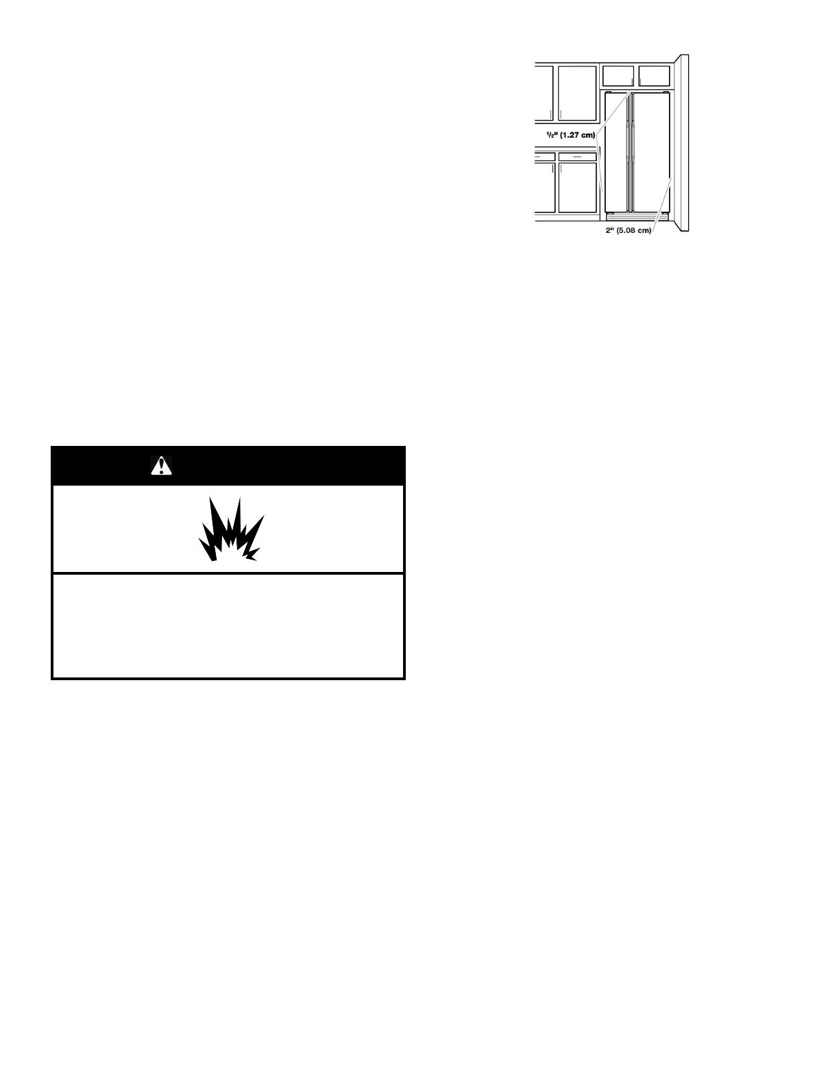
For Standard Side-by-Side Installation:
To ensure proper ventilation for your refrigerator, allow for 1/2"
(1.27 cm) of space on each side and at the top. Allow for 2" (5.08
cm) of space behind the refrigerator. If your refrigerator has an ice
maker, allow extra space at the back for the water line
connections. When installing your refrigerator next to a fixed wall,
leave a 2" (5.08 cm) minimum space on each side (depending on
your model) to allow the doors to swing open.
NOTES:
This refrigerator is intended for use in a location where the
temperature ranges from a minimum of 55°F (13°C) to a
maximum of 110°F (43°C). The preferred room temperature
range for optimum performance, which reduces electricity
usage and provides superior cooling, is between 60°F (15°C)
and 90°F (32°C). It is recommended that you do not install the
refrigerator near a heat source, such as an oven or radiator.
Normal minimum cabinet cut-out width required for product
installation is 36" (91.44 cm). However, if the product is placed
against an extended wall and the ability to remove the crisper
pans is desired, an additional 18" (45.72 cm) of cabinet width
is required, so a total cabinet opening width of 54" (137.16 cm)
is recommended.
For Counter-Depth Side-by-Side Installation:
NOTES:
The refrigerator can be installed into a recessed opening, at
the end of cabinets or as a freestanding refrigerator.
If you are installing the refrigerator to fit flush with the front of
the base cabinets, all shoe moulding and baseboards must be
removed from the rear of the refrigerator opening. Allow for 1"
(2.54 cm) of space behind the refrigerator.
Location should permit doors to open fully. See “Product
Dimensions.”
This refrigerator is intended for use in a location where the
temperature ranges from a minimum of 55°F (13°C) to a
maximum of 110°F (43°C). The preferred room temperature
range for optimum performance, which reduces electricity
usage and provides superior cooling, is between 60°F (15°C)
and 90°F (32°C). It is recommended that you do not install the
refrigerator near a heat source, such as an oven or radiator.
Floor must support refrigerator weight (more than 600 lbs.
[272 kg]) and contents.
Tools Needed:
Gather the required tools and parts before starting installation.
Read and follow the instructions provided with any tools listed
here.
Cordless drill
1/4" nut driver and drill bit
Flat-blade screwdriver
Two adjustable wrenches
5/16" or adjustable wrench
7/16" and 1/2" open-end
wrenches
3/8" and 1/2" socket
wrenches
Parts Needed:
Your refrigerator dealer has a kit available with a 1/4" (6.35
mm) saddle-type shutoff valve, a union, and copper tubing.
Or you can purchase 1/4" (6.35 mm) copper tubing with shutoff
valve and a 1/4" (6.35 mm) compression fitting (coupling).
Depending on water line connections, you may also need a
1/4" (6.35 mm) nut and 1/4" (6.35 mm) ferrule.
7
Product Dimensions Top View
Door
Style
Depth A Depth B Depth C
Flat 27 1/2"
(69.9 cm)
2 5/8" (6.7 cm)
maximum*
30" (76.2 cm)
maximum*
Curved 28 5/8"
(72.7 cm)
2 5/8" (6.7 cm) 31 1/8" (79.1 cm)
*Dimension may vary based on style of door handle.
The depth for the largest available handle is listed.
Product Dimensions Front View
Model Size Height A
69" 65 3/4" (167.0 cm)
72" 68 1/8" (173.0 cm)
Product Dimensions Side View
Height dimensions are shown with the leveling legs extended
to the minimum height of 1/4" (6.35 mm) below the refrigerator.
NOTE: When leveling legs are fully extended to 1" (25 mm)
below the refrigerator, add 3/4" (19 mm) to the height
dimensions.
The power cord is 61 1/4" (155.6 cm) long.
The water line attached to the back of the refrigerator is 78"
(198.1 cm) long.
Model Size Height A Height B Height C
69" 68 7/8"
(174.9 cm)
68 7/8"
(174.9 cm)
68 1/2"
(174.0 cm)
72" 71 1/4"
(181.0 cm)
71 1/4"
(181.0 cm)
71"
(180.3 cm)
8
Opening Dimensions
Height dimensions are shown with the leveling legs extended
to the minimum height of 1/4" (6.35 mm) below the refrigerator.
NOTE: When leveling legs are fully extended to 1" (25 mm)
below the refrigerator, add 3/4" (19 mm) to the height
dimensions.
In the following graphic, “A” represents the opening height
required for standard cabinets. For full-overlay cabinet doors
with a trim kit, add 1/8" (0.3 cm).
In the following graphic, “B” represents the distance needed to
fully open the freezer door and “C” represents the distance
needed to fully open the refrigerator door.
Model Size
and Door
Style
Height A Width B Width C
69" Flat 69"
(175.3 cm)
13 5/8"
(34.6 cm)
maximum*
18 1/8"
(46.0 cm)
maximum*
72" Flat 72"
(182.9 cm)
71 1/4"
(181.0 cm)
maximum*
18 1/8"
(46.0 cm)
maximum*
69" Curved 69"
(175.3 cm)
13 5/8"
(34.6 cm)
18 3/8"
(46.7 cm)
72" Curved 72"
(182.9 cm)
13 3/4"
(34.9 cm)
18 3/8"
(46.7 cm)
*Dimension may vary based on style of door handle.
The width for the largest available handle is listed.
Door Swing Dimensions
Location must permit doors to open to a minimum of 165°.
In the following graphic, “A” represents the distance needed to
fully open the freezer door and “B” represents the distance
needed to fully open the refrigerator door.
Dimension Flat Doors Curved Doors
A 13 5/8" (34.6 cm)
maximum*
13 3/4" (34.9 cm)
B 18 1/8" (46.0 cm)
maximum*
18 3/8" (46.7 cm)
C 2 3/4" (7.0 cm)
maximum*
3 3/4" (9.5 cm)
D 1/8" (0.3 cm) 1 1/4" (3.2 cm)
*Dimension may vary based on style of door handle.
The width for the largest available handle is listed.
Electrical Requirements
WARNING
Electrical Shock Hazard
Plug into a grounded 3 prong outlet.
Do not remove ground prong.
Do not use an adapter.
Do not use an extension cord.
Failure to follow these instructions can result in death,
fire, or electrical shock.
Before you move your refrigerator into its final location, it is
important to make sure you have the proper electrical connection.
Recommended Grounding Method
A 115 V, 60 Hz, AC-only, 15 A or 20 A fused, grounded electrical
supply is required. It is recommended that a separate circuit
serving only your refrigerator be provided. Use an outlet that
cannot be turned off by a switch. Do not use an extension cord.
9
NOTE: Before performing any type of installation, cleaning, or
removing a light bulb, turn cooling off or turn the control
(thermostat, refrigerator, or freezer control depending on the
model) to Off. Then disconnect the refrigerator from the electrical
source. When you are finished, reconnect the refrigerator to the
electrical source. Turn cooling on or reset the control (thermostat,
refrigerator, or freezer control depending on the model) to the
desired setting. See “Control Descriptions” in the Quick Start
Guide.
Water Supply Requirements
Gather the required tools and parts before starting installation.
Read and follow the instructions provided with any tools listed
here.
Tools Needed:
Flat-blade screwdriver
7/16" and 1/2" open-end or two
adjustable wrenches
1/4" nut driver
1/4" drill bit
Cordless drill
NOTE: Your refrigerator dealer has a kit available with a 1/4"
(6.35 mm) saddle-type shutoff valve, a union, and copper or PEX
tubing. Before purchasing, make sure a saddle-type valve
complies with your local plumbing codes. Do not use a piercing-
type or 3/16" (4.76 mm) saddle valve, which reduces water flow
and clogs more easily.
IMPORTANT:
All installations must meet local plumbing code requirements.
Use copper or PEX tubing and check for leaks. Install copper
or PEX tubing only in areas where the household temperatures
will remain above freezing.
Water Pressure
A cold water supply with water pressure of between 30 and 120
psi (207 and 827 kPa) is required to operate the water dispenser
and ice maker. If you have questions about your water pressure,
call a licensed, qualified plumber.
If your refrigerator has a water dispenser: After installation is
complete, use the water dispenser to check the water pressure.
With the water filter removed, dispense 1 cup (237 mL) of
water. If 1 cup of water is dispensed in 8 seconds or less, the
water pressure to the refrigerator meets the minimum
requirement.
If it takes longer than 8 seconds to dispense 1 cup of water, the
water pressure to the refrigerator is lower than recommended.
See online “Troubleshooting” for suggestions.
Reverse Osmosis Water Supply
IMPORTANT: The pressure of the water supply coming out of a
reverse osmosis system going to the water inlet valve of the
refrigerator needs to be between 30 and 120 psi (207 and 827
kPa).
If a reverse osmosis water filtration system is connected to your
cold water supply, the water pressure to the reverse osmosis
system needs to be a minimum of 40 to 60 psi (276 to 414 kPa).
If the water pressure to the reverse osmosis system is less than
40 to 60 psi (276 to 414 kPa):
Check to see whether the sediment filter in the reverse
osmosis system is blocked. Replace the filter if necessary.
Allow the storage tank on the reverse osmosis system to refill
after heavy usage.
If your refrigerator has a water filter, it may further reduce the
water pressure when used in conjunction with a reverse
osmosis system. Remove the water filter. See “Water Filtration
System”.
If you have questions about your water pressure, call a licensed,
qualified plumber.
Connect Water Supply
Read all directions before you begin.
IMPORTANT:
Connect to potable water supply only.
Plumbing shall be installed in accordance with the
International Plumbing Code and any local codes and
ordinances.
The gray water tubing on the back of the refrigerator (which is
used to connect to the household water line) is a PEX (cross-
linked polyethylene) tube. Copper or PEX tubing connections
from the household water line to the refrigerator are
acceptable, and will help avoid off-taste or odor in your ice or
water. Check for leaks. For recommended parts if PEX tubing
is used instead of copper:
W10505928RP (7 ft. [2.14 m] jacketed PEX),
8212547RP (5 ft. [1.52 m] PEX), or
W10267701RP (25 ft. [7.62 m] PEX).
Install tubing only in areas where temperatures will remain
above freezing.
Tools Needed:
Gather the required tools and parts before starting installation.
Read and follow the instructions provided with any tools listed
here.
Flat-blade screwdriver
7/16" and 1/2" open-end wrenches or two adjustable wrenches
1/4" nut driver
Connect to Water Line
IMPORTANT: If you turn on the refrigerator before the water line is
connected, turn off the ice maker.
Style 1 (Recommended)
1. Unplug refrigerator or disconnect power.
2. Turn off main water supply. Turn on nearest faucet long
enough to clear line of water.
3. Use a quarter-turn shutoff valve or the equivalent, served by a
1/2" copper or PEX household supply line.
NOTE: To allow sufficient water flow to the refrigerator, a
minimum 1/2" size copper or PEX household supply line is
recommended.
A. Bulb
B. Nut
C. Copper or PEX tubing (to refrigerator)
D. Household supply line (½" minimum)
10
4. Now you are ready to connect the copper or PEX tubing to the
shutoff valve. Use 1/4" (6.35 mm) O.D. (outside diameter) soft
copper or PEX tubing to connect the shutoff valve and the
refrigerator.
Ensure that you have the proper length needed for the job.
Be sure both ends of the copper tubing are cut square.
Slip compression sleeve and compression nut onto copper
tubing as shown. (PEX tubing has compression sleeves
and compression nuts preinstalled.) Insert end of tubing
into outlet end squarely as far as it will go. Screw
compression nut onto outlet end with adjustable wrench.
Do not overtighten.
A. Compression sleeve
B. Compression nut
C. Copper or PEX tubing
5. Place the free end of the tubing into a container or sink, and
turn on main water supply to flush out tubing until water is
clear. Turn off shutoff valve on the water pipe.
NOTE: Always drain the water line before making the final
connection to the inlet of the water valve, to avoid possible
water valve malfunction.
6. Bend the copper or PEX tubing to meet the water line inlet,
which is located on the back of the refrigerator cabinet. Leave
a coil of copper or PEX tubing to allow the refrigerator to be
pulled out of the cabinet or away from the wall for service.
Style 2
1. Unplug refrigerator or disconnect power.
2. Turn off main water supply. Turn on nearest faucet long
enough to clear line of water.
3. Locate a 1/2" (1.27 cm) to 1 1/4" (3.18 cm) vertical cold water
pipe near the refrigerator.
IMPORTANT:
Make sure it is a cold water pipe.
Horizontal pipe will work, but drill on the top side of the
pipe, not the bottom. This will help keep water away from
the drill and normal sediment from collecting in the valve.
4. Determine the length of copper or PEX tubing you need.
Measure from the connection on the lower rear corner of
refrigerator to the water pipe. Add 7 ft. (2.1 m) to allow for
cleaning. Use 1/4" (6.35 mm) O.D. (outside diameter) copper
or PEX tubing. Be sure both ends of copper or PEX tubing are
cut square.
5. Using a cordless drill, drill a 1/4" (6.35 mm) hole in the cold
water pipe you have selected.
A. Cold water pipe
B. Pipe clamp
C. Copper or PEX tubing
D. Compression nut
E. Compression sleeve
F. Shutoff valve
G. Packing nut
6. Fasten the shutoff valve to the cold water pipe with the pipe
clamp. Be sure the outlet end is solidly in the 1/4" (6.35 mm)
drilled hole in the water pipe and that the washer is under the
pipe clamp. Tighten the packing nut. Tighten the pipe clamp
screws slowly and evenly so the washer makes a watertight
seal. Do not overtighten, or you may crush the copper or PEX
tubing.
7. Slip compression sleeve and compression nut onto copper
tubing as shown. (PEX tubing has compression sleeves and
compression nuts preinstalled.) Insert end of tubing into outlet
end squarely as far as it will go. Screw compression nut onto
outlet end with adjustable wrench. Do not overtighten.
8. Place the free end of the tubing in a container or sink, and turn
on the main water supply. Flush the tubing until water is clear.
Turn off the shutoff valve on the water pipe. Coil the tubing.
Connect to Refrigerator
Style 1
1. Unplug refrigerator or disconnect power.
2. Remove and discard the short, black plastic part from the end
of the water line inlet.
3. Thread the nut onto the end of the tubing. Tighten the nut by
hand. Then tighten it with a wrench two more turns. Do not
overtighten.
NOTE: To avoid rattling, be sure the copper tubing does not
touch the cabinet’s side wall or other parts inside the cabinet.
A. Household water line
B. Nut (purchased)
C. Ferrule (purchased)
D. Refrigerator water tubing
4. Install the water supply tube clamp around the water supply
line to reduce strain on the coupling.
5. Turn shutoff valve on.
6. Check for leaks. Tighten any connections (including
connections at the valve) or nuts that leak.
Style 2
1. Unplug refrigerator or disconnect power.
2. Remove and discard the plastic part that is attached to the
inlet of the water valve.
3. Attach the copper or PEX tube to the valve inlet using a
compression nut and sleeve as shown. Tighten the
compression nut. Do not overtighten.
A. Tube clamp
B. Tube clamp screw
C. Copper tubing
D. Compression nut
E. Valve inlet
11
4. Use the tube clamp on the back of the refrigerator to secure
the tubing to the refrigerator as shown. This will help avoid
damage to the tubing when the refrigerator is pushed back
against the wall.
5. Turn shutoff valve on.
6. Check for leaks. Tighten any connections (including
connections at the valve) or nuts that leak.
7. On some models, the ice maker is equipped with a built-in
water strainer. If your water conditions require a second water
strainer, install it in the 1/4" (6.35 mm) water line at either tube
connection. Obtain a water strainer from your nearest
appliance dealer.
Style 3
1. Unplug refrigerator or disconnect power.
2. Remove and discard the black nylon plug from the gray water
tube on the rear of the refrigerator.
3. If the gray water tube supplied with the refrigerator is not long
enough, a 1/4" x 1/4" (6.35 mm x 6.35 mm) coupling is needed
in order to connect the water tubing to an existing household
water line. Thread the provided nut onto the coupling on the
end of the copper or PEX tubing.
NOTE: Tighten the nut by hand. Then tighten it with a wrench
two more turns. Do not overtighten.
A. Refrigerator water
tubing
B. Nut (provided)
C. Bulb
D. Coupling (purchased)
E. Ferrule (purchased)
F. Nut (purchased)
G. Household water line
4. Turn shutoff valve on.
5. Check for leaks. Tighten any connections (including
connections at the valve) or nuts that leak.
Complete the Installation
WARNING
Electrical Shock Hazard
Plug into a grounded 3 prong outlet.
Do not remove ground prong.
Do not use an adapter.
Do not use an extension cord.
Failure to follow these instructions can result in death,
fire, or electrical shock.
1. Plug into a grounded 3–prong outlet.
2. Wait a few minutes. Check that the compressor is operating
properly and that all lights are working.
NOTE: If the refrigerator does not operate, check that the
circuit breaker is not tripped or that the household fuse has not
blown.
3. Flush the water system. See “Water and Ice Dispensers.”
NOTE: Allow 24 hours to produce the first batch of ice. Allow
72 hours to completely fill ice container.
IMPORTANT: If construction will continue after refrigerator has
been installed, unplug refrigerator or disconnect power.
Install Air Filter (on some models)
On some models, your refrigerator's accessory packet includes an
air filter, which must be installed prior to use. On some models,
the air filter is already installed at the factory. To order a
replacement air filter, use part number W10311524.
The air filter reduces the buildup of odors. This helps to maintain a
cleaner environment inside the refrigerator.
Installing the Air Filter
The filter should be installed behind the vented door, which is
located (depending on your model) along either the rear or left
interior wall near the top of the refrigerator compartment.
1. Remove the air filter from its packaging.
2. Lift open the vented door.
3. Snap the filter into place.
4. Close the vented door.
Installing the Filter Status Indicator (on some
models)
The filter comes with a status indicator, which should be activated
and installed at the same time the air filter is installed.
12
1. Place the indicator facedown on a firm, flat surface.
2. Apply pressure to the bubble on the back of the indicator, until
the bubble pops to activate the indicator.
3. Lift open the vented air filter door. On some models, there are
notches behind the door.
4. On models with notches:
Slide the indicator down into the notches, facing outward.
NOTE: The indicator will not easily slide into the notches if
the rear bubble has not been popped.
Close the air filter door, and check that the indicator is
visible through the rectangular hole in the door.
On models without notches:
Place the indicator in a visible place you will easily
remember—either inside the refrigerator or elsewhere in
your kitchen or home.
Replacing the Air Filter
The disposable air filter should be replaced every 6 months, when
the status indicator has completely changed from white to red.
To order a replacement air filter, see ordering information in the
Quick Start Guide.
1. Remove the old air filter by squeezing in on the side tabs.
2. Remove the old status indicator.
3. Install the new air filter and status indicator using the
instructions in the previous sections.
Install Produce Preserver (on some
models)
Your refrigerator's accessory packet includes a Produce
Preserver, which should be installed prior to use. On some
models, the Produce Preserver is already installed at the factory.
To order a replacement produce preserver, use part number
W10346771.
The Produce Preserver absorbs ethylene, allowing the ripening
process of many produce items to slow down. As a result, certain
produce items will stay fresh longer.
Ethylene production and sensitivity varies depending on the type
of fruit or vegetable. To preserve freshness, it is best to separate
produce with sensitivity to ethylene from fruits that produce
moderate to high amounts of ethylene.
Sensitivity to
Ethylene
Ethylene
Production
Apples High Very High
Asparagus Medium Very Low
Berries Low Low
Broccoli High Very Low
Cantaloupe Medium High
Carrots Low Very Low
Citrus Fruit Medium Very Low
Grapes Low Very Low
Lettuce High Very Low
Pears High Very High
Spinach High Very Low
Installing the Produce Preserver
CAUTION: IRRITANT. MAY IRRITATE EYES AND SKIN.
DANGEROUS FUMES FORM WHEN MIXED WITH OTHER
PRODUCTS.
MAY IRRITATE EYES AND SKIN. DANGEROUS FUMES FORM
WHEN MIXED WITH OTHER PRODUCTS.
Do not mix with cleaning products containing ammonia, bleach, or
acids. Do not get in eyes, on skin or clothing. Do not breathe dust.
Keep out of reach of children.
FIRST AID TREATMENT: Contains potassium permanganate. If
swallowed, call a Poison Control Center or doctor immediately. Do
not induce vomiting. If in eyes, rinse with water for 15 minutes. If
on skin, rinse with water.
The Produce Preserver pouches should be installed in their
housing, which is located along an interior side wall of the crisper
or convertible drawer.
NOTE: For best performance, always use two pouches.
1. Remove the Produce Preserver pouches from their
packaging.
2. Lift up on the housing in order to remove it from its mounting
tab along the wall.
3. Open the housing by pulling up and out on the back of the top
of the housing.
4. Place both pouches inside the housing; then snap the housing
back together.
5. Place the housing back on the mounting tab along the wall.
Installing the Status Indicator
The Produce Preserver comes with a status indicator, which
should be activated and installed at the same time the pouch is
installed.
1. Place the indicator facedown on a firm, flat surface.
2. Apply pressure to the bubble on the back of the indicator, until
the bubble pops to activate the indicator.
3. Slide open the cap on the Produce Preserver housing.
4. Place the indicator in the top of the housing, facing outward.
5. Slide the cap closed, and check that the indicator is visible
through the rectangular hole in the cap.
NOTE: The cap will not close easily if the indicator’s rear
bubble has not been popped.
13
Replacing the Produce Preserver Pouches
The disposable pouches should be replaced every 6 months,
when the status indicator has completely changed from white to
red.
To order replacements, see the contact information in the Quick
Start Guide. Order part number W10346771A or FRESH1.
1. Remove the used pouches from the produce preserver
housing.
2. Remove the old status indicator.
3. Install the new pouches and status indicator using the
instructions in the previous sections.
REFRIGERATOR FEATURES
Convertible Drawer Temperature
Control (on some models)
The control can be adjusted to properly chill meats or vegetables.
The air inside the pan is cooled to avoid “spot” freezing and can
be set to keep meats at the National Livestock and Meat Board
recommended storage temperatures of 28° to 32°F (–2° to 0°C).
To store meat:
Set the control to one of the three Meat settings to store meat at
its optimal storage temperature.
To store vegetables:
Set the control to Veg to store vegetables at their optimal storage
temperatures.
NOTE: If food starts to freeze, move the control to the right (less
cold), toward the Veg setting. Remember to wait 24 hours
between adjustments.
Crisper Humidity Control (on some
models)
You can control the amount of humidity in the moisture-sealed
crisper. Adjust the control to any setting between Low and High.
LOW (open) for best storage of fruits and vegetables with skins.
HIGH (closed) for best storage of fresh, leafy vegetables.
Dual Evaporator (on some models)
Some models come equipped with a dual sequential evaporation
system which includes two separate evaporators for the
refrigerator and freezer compartments.
Dual evaporation results in higher humidity, which helps keep
foods in the refrigerator from spoiling as quickly and improves
food quality and freshness in the freezer due to decreased freezer
burn. In addition, the dual evaporation system helps keep food
smells in the refrigerator from transferring to ice in the freezer.
NOTE: The dual evaporation system is always activated when
your refrigerator is operating. You do not need to press any
buttons to turn it on.
Water and Ice Dispensers
On how to use your water and ice dispensers, see the online
“Side-by-Side Refrigerator Dispensers” Feature Guide.
NOTES:
Connect to potable water supply only.
The dispensing system will not operate when either door
(refrigerator or freezer) is open.
Allow 24 hours for the refrigerator to cool down and chill water.
Allow 24 hours to produce the first batch of ice. Discard the
first three batches of ice produced. Wait 72 hours for full ice
production.
On some models, the display screen on the dispenser control
panel will turn off automatically and enter “sleep” mode when
the control buttons and dispenser pads have not been used for
2 minutes or more. While in “sleep” mode, the first press of a
control button will only reactivate the display screen, without
changing any settings.
Flush the Water System
Air in the water dispensing system can cause the water dispenser
to drip. After connecting the refrigerator to a water source or
replacing the water filter, flush the water system. Flushing the
water dispensing system forces air from the water line and filter
and prepares the water filter for use.
NOTE: As air is cleared from the system, water may spurt out of
the dispenser.
1. Using a sturdy container, depress and hold the water
dispenser pad for 5 seconds; then release it for 5 seconds.
2. Repeat step 1 until water begins to flow.
3. Once water begins to flow, continue depressing and releasing
the dispenser pad (5 seconds on, 5 seconds off) until a total of
3 gal. (12 L) has been dispensed.
Additional flushing may be required in some households.
The Water Dispenser
IMPORTANT:
Dispense at least 1 qt. (1 L) of water every week to maintain a
fresh supply.
If the flow of water from the dispenser decreases, it could be
caused by low water pressure.
With the water filter removed, dispense 1 cup (237 mL) of
water. If 1 cup of water is dispensed in 8 seconds or less, the
water pressure to the refrigerator meets the minimum
requirement.
If it takes longer than 8 seconds to dispense 1 cup of water, the
water pressure to the refrigerator is lower than recommended.
See “Water Supply Requirements” or online “Troubleshooting”
for suggestions.
Ice Maker and Storage Bin
Allow 24 hours to produce the first batch of ice. Discard the
first three batches of ice produced.
The quality of your ice will be only as good as the quality of the
water supplied to your ice maker. Avoid connecting the ice
maker to a softened water supply. Water softener chemicals
(such as salt) can damage parts of the ice maker and lead to
poor quality ice. If a softened water supply cannot be avoided,
make sure the water softener is operating properly and is well
maintained.
Do not use anything sharp to break up the ice in the storage
bin. This can cause damage to the ice container and the
dispenser mechanism.
Do not store anything on top of or in the ice maker or storage
bin.
14
Style 1
Turning the Ice Maker On/Off:
The On/Off switch, located on the left wall of the freezer door, can
only be accessed when the ice storage bin has been removed.
See the following section for bin removal instructions.
To turn on the ice maker, flip the switch to the On (up) position.
To manually turn off the ice maker, flip the switch to the Off
(down) position.
NOTE: The ice maker has an automatic shutoff to keep the
storage bin from overfilling during normal operation. As ice is
made, the ice cubes will fill the ice storage bin, and the ice cubes
will raise the shutoff arm to the Off (arm up) position. When the
storage bin is at full capacity, the ice maker will automatically stop
ice production, but the ice maker On/Off switch will remain in the
On (up) position.
Ice production Off
(Shutoff arm up)
Ice production On
(Shutoff arm down)
Removing and Replacing the Ice Storage Bin:
1. Press down the release lever and tilt the bucket outward. Use
both hands to hold the base of the storage bin, and then lift it
up and out.
A. Release lever
NOTE: It is not necessary to flip the ice maker On/Off switch
to the Off (down) position when removing the storage bin. The
storage bin sensor, located on the left wall (right wall on some
models) of the freezer door, stops the ice maker from
producing ice if the door is open or the storage bin is removed.
A. On/Off switch B. Storage bin sensor
2. Replace the bin by sliding it onto the door, and then tilting it
back into an upright position. The release lever will click when
the bin is securely in place.
Style 2
Turning the Ice Maker On/Off:
To turn on the ice maker, lower the wire shutoff arm to the On
position.
To manually turn off the ice maker, lift the wire shutoff arm to
the Off (arm up) position and listen for the click. Ice can still be
dispensed, but no more can be made.
NOTE: The ice maker has an automatic shutoff to keep the
storage bin from overfilling during normal operation. As ice is
made, the ice cubes will fill the ice storage bin, and the ice cubes
will raise the wire shutoff arm to the Off (arm up) position. Do not
force the wire shutoff arm up or down.
Removing and Replacing the Ice Storage Bin:
1. Pull the covering panel up from the bottom.
2. Lift the wire shutoff arm so it clicks into the Off (up) position.
3. Lift up the front of the storage bin and pull it out.
4. Replace the bin by pushing it in all the way or the dispenser
will not work.
5. To restart ice production, lower the wire shutoff arm to the On
(down) position. Make sure the door is closed tightly.
Style 3
Turning the Ice Maker On/Off:
To turn on the ice maker, lift open the ice maker door and lower
the wire shutoff arm to the On position.
To manually turn off the ice maker, lift the wire shutoff arm to
the Off (arm up) position and listen for the click. Ice can still be
dispensed, but no more can be made.
15
NOTE: The ice maker has an automatic shutoff to keep the
storage bin from overfilling during normal operation. As ice is
made, the ice cubes will fill the ice storage bin, and the ice cubes
will raise the wire shutoff arm to the Off (arm up) position. Do not
force the wire shutoff arm up or down.
Removing and Replacing the Ice Storage Bin:
1. Lift and hold open the ice maker door.
2. Lift the wire shutoff arm so it clicks into the Off (up) position.
Release the ice maker door.
3. Lift up the front of the storage bin and pull it out.
4. Replace the bin by pushing it in all the way or the dispenser
will not work.
5. To restart ice production, lift open the ice maker door and push
the wire shutoff arm down to the On position.
Style 4
Turning the Ice Maker On/Off:
The On/Off switch is located on the bottom of the ice maker, which
can be accessed by lifting and opening the ice maker door.
To turn on the ice maker, lift open the ice maker door, and flip
the switch to the On (right) position.
To manually turn off the ice maker, lift open the ice maker door,
and flip the switch to the Off (left) position. Ice can still be
dispensed, but no more can be made.
NOTE: Your ice maker has an automatic shutoff to keep the
storage bin from overfilling during normal operation. As ice is
made, the ice cubes will fill the ice storage bin, and the ice cubes
will raise the shutoff arm to the Off (arm up) position. When the
storage bin is at full capacity, the ice maker will automatically stop
ice production, but the ice maker On/Off switch will remain in the
On (up) position.
Removing and Replacing the Ice Storage Bin:
1. Pull the covering panel up from the bottom.
2. Lift the plastic shutoff arm so it clicks into the Off (up) position.
3. Lift up the front of the storage bin and pull it out.
4. Replace the bin by pushing it in all the way or the dispenser
will not work.
5. To restart ice production, lower the plastic shutoff arm to the
On (down) position. Make sure the door is closed tightly.
Water Filtration System
Do not use with water that is microbiologically unsafe or of
unknown quality without adequate disinfection before or after the
system. Systems certified for cyst reduction may be used on
disinfected waters that may contain filterable cysts.
Water Filter Status Light
The water filter status light will help you know when to change
your water filter. This is located on the refrigerator control panel.
To order a replacement water filter use part number W10295370A
(P4RFWB).
Style 1 Order and Replace status:
When the dispenser control panel’s water filter status display
changes to “Order,” this tells you that it is almost time to
change the water filter cartridge.
Replace the water filter cartridge when the water filter status
display changes to “Replace.”
NOTE: If water flow to your water dispenser or ice maker
decreases noticeably, change the filter sooner. The filter
should be replaced at least every 6 months, depending on
your water quality and usage.
Style 2 Red light status:
When the light turns red on the control panel, this tells you that
it is time to change the water filter cartridge.
It is recommended that you replace the filter when the status
light turns red or water flow to your water dispenser or ice
maker decreases noticeably.
NOTE: The filter should be replaced at least every 6 months,
depending on your water quality and usage.
Resetting the Filter Status
After changing the water filter, reset the status light.
For models with the Options button:
Press the Options button to enter Options mode, press Lock to
initiate the reset, and then press Measured Fill to confirm that
you want to reset the status light. When the system is reset,
the “Order” and “Replace” icons will disappear from the display
screen.
For models with the Filter button:
Press and hold the Filter button for 3 seconds to reset the
status light. When the system is reset, the “Order” and
“Replace” icons will disappear from the display screen.
For models with the Temp Setting button:
The reset button is located on the control panel in the
refrigerator compartment. To reset the status light after
changing the filter, press Temp Setting within 3 seconds. The
status light will change from red to off when the system is
reset.
For models with the Light and Ice Type buttons:
Reset the filter status light by pressing and hold Light and Ice
Type buttons for 3 seconds. The status light will turn off when
the system is reset.
16
Changing the Water Filter
Style 1 Top-right corner location:
1. Locate the water filter in the top-right corner of the refrigerator
compartment.
2. Lift open the filter cover door. The filter will be released and
then be ejected as the door is opened.
3. When the door is completely open, pull the filter straight out.
NOTE: There may be some water in the filter. Some spilling
may occur. Use a towel to wipe up any spills.
4. Take the new filter out of its packaging and remove the cap.
Be sure the O-rings are still in place after the cap is removed.
A. Cap B. O-rings
5. With the arrow pointing up, align the new filter with the filter
housing and slide it into place. The filter cover door will
automatically begin to close as the new filter is inserted.
6. Close the filter cover door completely in order to snap the filter
into place. You may need to press hard.
7. After changing the filter, reset the filter status light.
8. Flush the water system. See “Water and Ice Dispensers” for
details.
Style 2 Base grille location (automatic ejection):
A. Water filter cover door
1. Locate the water filter cover door in the base grille, and pull
open the filter door. The filter will be released and then be
ejected as the door is opened.
2. When the door is completely open, pull the filter straight out.
NOTE: There may be some water in the filter. Some spilling
may occur. Use a towel to wipe up any spills.
3. Take the new filter out of its packaging and remove the covers
from the O-rings. Be sure the O-rings are still in place after the
covers are removed.
4. With the arrow pointing to the left (toward the filter cover
doors hinge), align the new filter with the filter housing and
slide into place. The filter cover door will automatically begin to
close as the new filter is inserted.
5. Close the filter cover door completely in order to snap the filter
into place. You may need to press hard.
6. Flush the water system. See “Water and Ice Dispensers” for
details.
Style 3 Base grille location (manual turn):
A. Water filter cover door
1. Locate the water filter cover door in the base grille, and pull
open the filter door.
2. Twist the water filter and turn 90° counterclockwise to unlock.
3. Pull the filter out of the housing.
17
4. Remove the water filter cap from the water filter.
5. Install the water filter cap onto the new filter. Be sure to align
the arrows so the grooves in the filter align with ribs in the filter
cap.
6. Insert the filter into the housing.
7. Twist the water filter and turn 90° clockwise until it locks into
place and the arrows are aligned.
8. Push the water filter door closed.
DOOR REMOVAL AND LEVELING
STYLE 1
Door Instructions
Gather the required tools and parts and read all instructions
before starting installation. Save these instructions for future
reference.
WARNING
Electrical Shock Hazard
Disconnect power before removing doors.
Failure to do so could result in death or electrical shock.
NOTE: Before moving your refrigerator into your home, measure
the doorway of your home to see whether you need to remove the
refrigerator and freezer doors. If door removal is necessary, see
the instructions below.
TOOLS NEEDED Depending on your model, you may need the
following: Bubble level, flat-blade screwdriver, Phillips screwdriver
tip #2 with 4” long as minimum, 3/16" hex key, 1/4", 3/8”, and 5/16”
hex-head socket wrench, 1/4" and 5/16" open-ended wrenches or
adjustable wrench, internal star drive or 3/8" hex-head socket
wrench, TORX T30 screwdriver.
Install and Remove Door Handles
Refrigerator Door Handle Style 1
PARTS INCLUDED: Door handles (2).
To Install the Handles:
1. Remove the handles, which are packed inside the refrigerator.
NOTE: To avoid scratching the finish, place the handles on a
towel or other soft surface.
2. Open the freezer door. On the refrigerator door, place the
handle on the shoulder screws.
A. Shoulder screws
3. Firmly push the handle toward the door until the handle base
is flush against the door.
4. While holding the handle, push downward until the handle is
released from the shoulder screw.
5. Open the refrigerator door and close the freezer door. Repeat
steps 2 through 4 to install the other handle onto the freezer
door
18
To Remove the Handles:
1. While holding the handle, push upward until the handle is
released from the shoulder screw.
2. Gently pull the handle away from the door.
3. If necessary, use a Phillips screwdriver to remove the shoulder
screws from the door.
Refrigerator Door Handle Style 2
PARTS INCLUDED: Door handles(2), 1/8” hex key, spare
setscrew(s)
NOTE: The handle mounting setscrews are pre-installed in the
handle.
1. Remove the handles, which are packed inside the refrigerator.
NOTE: To avoid scratching the finish, place the handles on a
towel or other soft surface.
2. Open the freezer door. On the refrigerator door, place the
handle on the shoulder screws with the setscrews facing the
freezer.
A. Shoulder screws B. Setscrews inside the
handle
3. Firmly push the handle toward the door until the handle base
is flush against the door.
4. While holding the handle, insert the short end of the hex key
into the upper hole and slightly rotate the hex key until it is
engaged in the setscrew.
5. Using a clockwise motion, tighten the setscrew until it begins
to contact the shoulder screw.
6. Repeat steps 4 and 5 to begin fastening the lower setscrew.
7. Once both setscrews have been partially tightened as outlined
in the previous steps, fully tighten both the upper and lower
setscrews.
IMPORTANT: When the screws feel tight, tighten them an
additional quarter-turn. The handle is not properly installed
without this extra tightening.
8. Open the refrigerator door and close the freezer door. Repeat
steps 2 through 7 to install the other handle onto the freezer
door with the setscrews facing the refrigerator.
9. Save the hex key and all instructions.
To Remove the Handles:
1. While holding the handle, insert the short end of the hex key
into the upper hole and slightly rotate the hex key until it is
engaged in the setscrew.
2. Using a counterclockwise motion, loosen the setscrew a
quarter-turn at a time.
3. Repeat steps 1 and 2 for the upper setscrew. Gently pull the
handle away from the door.
4. If necessary, use a Phillips screwdriver to remove the shoulder
screws from the door.
Remove Doors and Hinges
If your refrigerator does not fit through the doorway or you are
getting rid of your old refrigerator, follow the steps below for door
removal.
WARNING
Electrical Shock Hazard
Disconnect power before removing doors.
Failure to do so could result in death or electrical shock.
1. Unplug refrigerator or disconnect power.
2. Fully open both doors.
3. If your model has water dispensing, please open the water
filter door by pulling it toward you as shown below. It is not
necessary to remove the water filter itself.
4. Pull the base grille toward you from the sides and then from
the center until it dislodges.
5. To remove the base grille, twist and pull the right side until this
side passes underneath the refrigerator door. Then pull the left
side of the base grille for complete removal.
19
6. If your model has water dispensing in the door, disconnect the
water dispenser tubing located below the freezer door.
Press the blue outer ring against the face of fitting and pull
the dispenser tubing free as shown below.
NOTE: Keep the water tubing connector attached to the
tube that runs underneath the freezer. The door cannot be
removed if the connector is still attached to the tube that
runs through the door hinge.
A. Face of fitting
7. If your model has water dispensing in the door, disconnect the
wiring located below the freezer door as shown below.
Remove the wiring clip and the bracket wire using a 1/4"
hexagonal-head socket wrench.
Disconnect the wiring plugs from the bracket wire.
A. Wiring plugs C. Grommets
B. Wiring clip
8. Close the freezer door and use a TORX T30 screwdriver to
remove the top hinge completely as shown below.
A. Do Not Remove Screws
IMPORTANT: Do not remove either screw A. Hold the door
while hinge is being removed.
9. Lift the freezer door straight up off from the bottom hinge as
shown below. The water dispenser tubing and wiring will
remain attached to the freezer door.
WARNING
Excessive Weight Hazard
Use two or more people to lift the appliance door.
Failure to do so can result in back or other injury.
NOTE: This may require two people, one to lift the door and
the other to feed the water tubing and wiring into the bottom
hinge pin.
IMPORTANT: Rest the door on its side on a soft, clean
surface, such as a towel, blanket, or piece of cardboard. This
will help to avoid scratching or damaging the door, water
tubing, and wiring.
10. Close the freezer door and use a TORX T30 screwdriver to
remove the top hinge completely as shown below.
A. Do not remove screws.
IMPORTANT: Do not remove either screw A. Hold the door
while hinge is being removed.
11. .Lift the refrigerator door straight up off from the bottom hinge
as shown below.
IMPORTANT: Rest the door on its side on a soft, clean
surface, such as a towel, blanket, or piece of cardboard. This
will help to avoid scratching or damaging the door.
20
12. If your refrigerator without doors does not pass through the
doorway, you may remove both bottom hinges. Use a 5/16"
nut driver to remove these as shown below..
B. Do not remove B screws
IMPORTANT: Do not remove either screw B.
Replace Doors and Hinges
If your doors and bottom hinges have been removed, please
follow the next instructions for reinstallation:
1. Reinstall both bottom hinges using a 5/16" nut driver to tighten
screws as shown below.
B. Do not remove B screws
2. If your model has water dispensing in the door:
Lift the freezer door enough to feed the water dispenser
tubing and wiring through the bottom hinge pin as shown
below.
NOTE: This may require two people, one to lift the door
and the other to feed the water tubing and wiring into the
bottom hinge pin.
IMPORTANT: Hold the door while hinge is being installed.
3. Close the freezer door to align and reinstall the top hinge. Use
a TORX T30 screwdriver to tighten the screws as shown
below.
A. Do not remove A screws
IMPORTANT: Provide additional support for the door while top
hinge is being reinstalled. Do not depend on the door magnets
to secure the door to the cabinet.
4. If your model has water dispensing in the door, connect the
water dispenser tubing. For the connection, push the tubing
into the dispenser tubing until black mark touches the face of
fitting as shown below.
A. Face of fitting
5. Connect the wiring as shown below.
A. Wiring plugs C. Grommets
B. Wiring clip
6. Reinstall the wiring clip & the bracket wire using a 1/4"
hexagonal head socket wrench.
7. Connect the wiring plugs from the bracket wire.
8. Lift the refrigerator door enough to insert the door onto the
bottom hinge pin as shown below.
IMPORTANT: Hold the door while hinge is being installed.
  • Page 1 1
  • Page 2 2
  • Page 3 3
  • Page 4 4
  • Page 5 5
  • Page 6 6
  • Page 7 7
  • Page 8 8
  • Page 9 9
  • Page 10 10
  • Page 11 11
  • Page 12 12
  • Page 13 13
  • Page 14 14
  • Page 15 15
  • Page 16 16
  • Page 17 17
  • Page 18 18
  • Page 19 19
  • Page 20 20
  • Page 21 21
  • Page 22 22
  • Page 23 23
  • Page 24 24
  • Page 25 25
  • Page 26 26
  • Page 27 27
  • Page 28 28
  • Page 29 29
  • Page 30 30
  • Page 31 31
  • Page 32 32
  • Page 33 33
  • Page 34 34
  • Page 35 35
  • Page 36 36
  • Page 37 37
  • Page 38 38
  • Page 39 39
  • Page 40 40
  • Page 41 41
  • Page 42 42
  • Page 43 43
  • Page 44 44
  • Page 45 45
  • Page 46 46
  • Page 47 47
  • Page 48 48
  • Page 49 49
  • Page 50 50
  • Page 51 51
  • Page 52 52
  • Page 53 53
  • Page 54 54
  • Page 55 55
  • Page 56 56

KitchenAid KRSC700HBS Owner's manual

Category
Fridges
Type
Owner's manual

Ask a question and I''ll find the answer in the document

Finding information in a document is now easier with AI

in other languages