

LIST OF ABBREVIATIONS
A
ampere(s)
lb
pound(s)
ABDC after bottom dead center
m
meter(s)
AC alternating current
min
minute(s)
ATDC
after top dead center
N
newton(s)
BBDC
before bottom dead center
P a
pascal (s)
BDC bottom dead center
P S
horsepower
BTDC before top dead center
psi pound(s) per square inch
°C degree(s) Celsius
r
revolution
DC
direct current rpm revolution(s) per minute
F farad (s) TDC top dead center
° F
degree(s) Fahrenheit
TIR
total indicator reading
ft foot, feet
V volt(s)
g
gram(s)
W watt(s)
h hour(s)
Q ohm(s)
L liter(s)
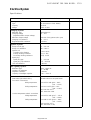
This warning may apply to any of the following
components or any assembly containing one or
more of these components:-
Brake Shoes or Pads
Clutch Friction Material
Gaskets
Insulators
SAFETY INSTRUCTIONS
• Operate if possible out of doors or in a well
ventilated place.
• Preferably use hand tools or low speed tools
equipped, if necessary, with an appropriate dust
extraction facility. If high speed tools are used,
they should always be so equipped.
• If possible, dampen before cutting or drilling.
• Dampen dust and place it in properly closed
receptacle and dispose of it safely.
Read OWNER'S MANUAL before operating.
http://mototh.com

Foreword
This manual is designed primarily for use by
trained mechanics in a properly equipped shop.
However, it contains enough detail and basic
information to make it useful to the owner who
desires to perform his own basic maintenance and
repair work. A basic knowledge of mechanics, the
proper use of tools, and workshop procedures must
be understood in order to carry out maintenance and
repair satisfactorily. Whenever the owner has
insufficient experience or doubts his ability to do the
work, all adjustments, maintenance, and repair
should be carried out only by qualified mechanics.
In order to perform the work efficiently and to
avoid costly mistakes, read the text, thoroughly
familiarize yourself with the procedures before
starting work, and then do the work carefully in a
clean area. Whenever special tools or equipment are
specified, do not use makeshift tools or equipment.
Precision measurements can only be made if the
proper instruments are used, and the use of substi-
tute tools may adversely affect safe operation.
For the duration of the warranty period,
we recommend that all repairs and scheduled
maintenance be performed in accordance with this
service manual. Any owner maintenance or repair
procedure not performed in accordance with this
manual may void the warranty.
To get the longest life out of your "JET SKI"
watercraft:
• Follow the Periodic Maintenance Chart in the
Service Manual.
• Be alert for problems and non-scheduled mainte-
nance.
• Use proper tools and genuine Kawasaki "JET SKI"
watercraft parts. Special tools, gauges, and testers
that are necessary when servicing Kawasaki "JET
SKI" watercraft are introduced by the Special Tool
Manual. Genuine part provided as spare parts are
listed in the Parts Catalog.
• Follow the procedures in this manual carefully.
Don't take shortcuts.
• Remember to keep complete records of mainte-
nance and repair with dates and any new parts
installed.
How to Use this Manual
In preparing this manual, we divided the product
into its major systems. These systems became the
manual's chapters. All information for a particular
system from adjustment through disassembly and
inspection is located in a single chapter.
The Quick Reference Guide shows you all of the
product's system and assists in locating their
chapters. Each chapter in turn has its own compre-
hensive Table of Contents.
The Periodic Maintenance Chart is located in the
General Information chapter. The chart gives a time
schedule for required maintenance operations.
If you want spark plug information, for example,
go to the Periodic Maintenance Chart first. The chart
tells you how frequently to clean and gap the plug.
Next, use the Quick Reference Guide to locate the
Electrical System chapter. Then, use the Table of
Contents on the first page of the chapter to find the
Spark Plug section.
Whenever you see these WARNING and
CAUTION symbols, heed their instructions! Always
follow safe operating and maintenance practices.
This warning symbol identifies special
instructions or procedures which, if not
correctly followed, could result in personal
injury, or loss of life.
This caution symbol identifies special
instructions or procedures which, if not
strictly observed, could result in damage to
or destruction of equipment.
http://mototh.com

This manual contains four more symbols (in
addition to WARNING and CAUTION) which will
help you distinguish different types of information.
NOTE
o This note symbol indicates points of partic-
ular interest for more efficient and convenient
operation.
• Indicates a procedural step or work to be done.
o Indicates a procedural sub-step or how to do the
work of the procedural step it follows. It also
precedes the text of a NOTE.
* Indicates a conditional step or what action to take
based on the results of the test or inspection in the
procedural step or sub-step it follows.
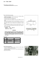
In most chapters an exploded view illustration of
the system components follows the Table of
Contents. In these illustrations you will find the
instructions indicating which parts require specified
tightening torque, oil, grease or a locking agent
during assembly.
http://mototh.com

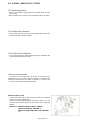
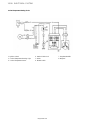
EMISSION CONTROL ll\lFORMATION
To protect the environment in which we all live, Kawasaki has incorporated crankcase emission
(1) and exhaust emission (2) control systems in compliance with applicable regulations of the
United States Environmental Protection Agency and California Air Resources Board. Additionally,
Kawasaki has incorporated an evaporative emission control system (3) in compliance with
applicable regulations of the California Air Resources Board on vehicles sold in California only.
1. Crankcase Emission Control System
This system eliminates the release of crankcase vapors into the atmosphere. Instead, the
vapors are routed through an oil separator to the intake side of the engine. While the engine
is operating, the vapors are drawn into combustion chamber, where they are burned along
with the fuel and air supplied by the carburetion system.
2. Exhaust Emission Control System
This system reduces the amount of pollutants discharged into the atmosphere by the exhaust
of this motorcycle. The fuel and ignition systems of this motorcycle have been carefully
designed and constructed to ensure an efficient engine with low exhaust pollutant levels.
3. Evaporative Emission Control System
Vapors caused by fuel evaporation in the fuel system are not vented into the atmosphere.
Instead, fuel vapors are routed into the running engine to be burned, or stored in a canister
when the engine is stopped. Liquid fuel is caught by a vapor separator and returned to the
fuel tank.
The Clean Air Act, which is the Federal law covering motor vehicle pollution, contains what is
commonly referred to as the Act's "tampering provisions."
"Sec. 203(a) The following acts and the causing thereof are prohibited...
(3) (A) for any person to remove or render inoperative any device or element of design installed
on or in a motor vehicle or motor vehicle engine in compliance with regulations under
this title prior to its sale and delivery to the ultimate purchaser, or for any manufacturer
or dealer knowingly to remove or render inoperative any such device or element of
design after such sale and delivery to the ultimate purchaser.
(3)(B) for any person engaged in the business of repairing, servicing, selling, leasing, or trading
motor vehicles or motor vehicle engines, or who operates a fleet of motor vehicles
knowingly to remove or render inoperative any device or element of design installed on
or in a motor vehicle or motor vehicle engine in compliance with regulations under this
title following its sale and delivery to the ultimate purchaser..."
(Continued on next page.)
http://mototh.com

NOTE
o The phrase "remove or render inoperative any device or element of design" has been
generally interpreted as follows:
1. Tampering does not include the temporary removal or rendering inoperative of
devices or elements of design in order to perform maintenance.
2. Tampering could include:
a. Maladjustment of vehicle components such that the emission standards are
exceeded.
b. Use of replacement parts or accessories which adversely affect the performance
or durability of the motorcycle.
c. Addition of components or accessories that result in the vehicle exceeding the
standards.
d. Permanently removing, disconnecting, or rendering inoperative any component
or element of design of the emission control systems.
WE RECOMMEND THAT ALL DEALERS OBSERVE THESE PROVISIONS OF FEDERAL
LAW, THE VIOLATION OF WHICH IS PUNISHABLE BY CIVIL PENALTIES NOT
EXCEEDING $10,000 PER VIOLATION.
TAMPERING WITH NOISE CONTROL SYSTEM PROHIBITED
Federal law prohibits the following acts or the causing thereof: (1) The removal or rendering
inoperative by any person other than for purposes of maintenance, repair, or replacement, of any
device or element of design incorporated into any new vehicle for the purpose of noise control prior
to its sale or delivery to the ultimate purchaser or while it is in use, or (2) the use of the vehicle after
such device or element of design has been removed or rendered inoperative by any person.
Among those acts presumed to constitute tampering are the acts listed below:
• Replacement of the original exhaust system or muffler with a component not in compliance with
Federal regulations.
• Removal of the muffler(s) or any internal portion of the muffler(s).
• Removal of the air box or air box cover.
• Modifications to the muffler(s) or air intake system by cutting, drilling, or other means if such
modifications result in increased noise levels.
http://mototh.com

Quick Reference Guide
This quick reference guide will assist you in
locating a desired topic or procedure.
• Bend the pages back to match the black tab
of the desired chapter number with the black
tab on the edge at each table of contents
page.
• Refer to the sectional table of contents for
the exact pages to locate the specific topic
required.
General Information
Fuel System
Cooling System
Engine Top End
Engine Right Side/Left Side
Engine Lubrication System
Engine Removal/Installation
Crankshaft/Transmission
Wheels/Tires
Final Drive
Brakes
Suspension
Steering
Frame
Electrical System
Appendix
Supplement -1994 Models
http://mototh.com

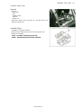
GENERAL INFORMATION 1-1
General Information
Table of Contents
Before Servicing 1-1
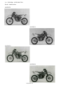
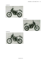
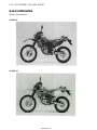
Model Identification 1 -4
General Specifications 1 -6
Periodic Maintenance Chart - KLX250D 1-10
Periodic Maintenance Chart - KLX250E 1 -12
Torque and Locking Agent 1 -14
Special Tools and Sealant 1-17
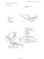
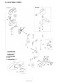
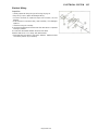
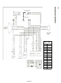
Cable, Wire and Hose Routing 1 -23
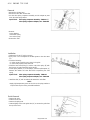
http://mototh.com

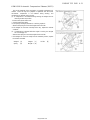
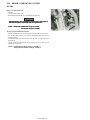
1-2 GENERAL INFORMATION
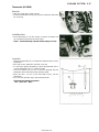
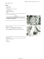
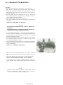
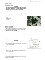
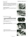
Before Servicing
Before starting to service a motorcycle, careful reading of the applicable section is recommended to eliminate
unnecessary work. Photographs, diagrams, notes, cautions, warnings, and detailed descriptions have been
included wherever necessary. Nevertheless, even a detailed account has limitations, a certain amount of basic
knowledge is also required for successful work.
Especially note the following:
(1) Dirt
Before removal and disassembly, clean the motorcycle. Any dirt entering the engine or other parts will
work as an abrasive and shorten the life of the motorcycle. For the same reason, before installing a new
part, clean off any dust or metal filings.
(2) Battery Ground
Remove the ground (-) lead from the battery before performing any disassembly operations on the
motorcycle. This prevents:
(a) the possibility of accidentally turning the engine over while partially disassembled.
(b) sparks at electrical connections which will occur when they are disconnected.
(c) damage to electrical parts.
(3) Tightening Sequence
Generally, when installing a part with several bolts, nuts, or screws, start them all in their holes and
tighten them to a snug fit. Then tighten them evenly in a cross pattern. This is to avoid distortion of the
part and/or causing gas or oil leakage. Conversely when loosening the bolts, nuts, or screws, first loosen
all of them by about a quarter turn and then remove them. Where there is a tightening sequence indication
in this Service Manual, the bolts, nuts, or screws must be tightened in the order and method indicated.
(4) Torque
When torque values are given in this Service Manual, use them. Either too little or too much torque may
lead to serious damage. Use a good quality, reliable torque wrench.
(5) Force
Common sense should dictate how much force is necessary in assembly and disassembly. If a part seems
especially difficult to remove or install, stop and examine what may be causing the problem. Whenever
tapping is necessary, tap lightly using a wooden or plastic-faced mallet. Use an impact driver for screws
(particularly for the removal of screws held by a locking agent) in order to avoid damaging the screw heads.
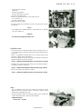
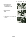
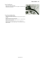
(6) Edges
Watch for sharp edges, especially during major engine disassembly and assembly. Protect your hands
with gloves or a piece of thick cloth when lifting the engine or turning it over.
(7) High-Flash Point Solvent
A high-flash point solvent is recommended to reduce fire danger. A commercial solvent commonly
available in North America is Stoddard solvent (generic name). Always follow manufacturer and container
directions regarding the use of any solvent.
(8) Gasket, 0-Ring
Do not reuse a gasket or O-ring once it has been in service. The mating surfaces around the gasket
should be free of foreign matter and perfectly smooth to avoid oil or compression leaks.
(9) Liquid Gasket, Non-Permanent Locking Agent
Follow manufacturer's directions for cleaning and preparing surfaces where these compounds will be
used Apply sparingly. Excessive amounts may block engine oil passages and cause serious damage. An
example of a non-permanent locking agent commonly available in North America is Loctite Lock'n Seal
(Blue).
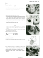
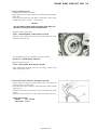
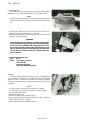
(10) Press .
A part installed using a press or driver, such as a wheel bearing, should first be coated with oil on its outer
or inner circumference so that it will go into place smoothly.
(11) Ball Bearing and Needle Bearing
Do not remove any ball or needle bearings that are pressed in unless it is necessary. If they are removed,
replace them with new ones.
When installing a bearing, press it in with the marked side facing out using a suitable driver until it is
bottomed. Bearings should be pressed into place by pushing evenly the bearing race which is affected by
friction.
http://mototh.com

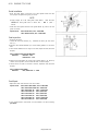
GENERAL INFORMATION 1-3
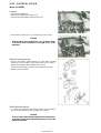
(12) Oil Seal and Grease Seal
Replace any oil or grease seals that were removed with new ones, as removal generally damages seals.
When pressing in a seal which has manufacturer's marks, press it in with the marks facing out. Seals
should be pressed into place using a suitable driver, which contacts evenly with the side of seal, until the
face of the seal is even with the end of the hole.
(13) Seal Guide
A seal guide is required for certain oil or grease seals during installation to avoid damage to the seal lips.
Before a shaft passes through a seal, apply a little high temperature grease on the lips to reduce rubber to
metal friction.
(14) Circlip, Retaining Ring
Replace any circlips and retaining rings that were removed with new ones, as removal weakens and
deforms them. When installing circlips and retaining rings, take care to compress or expand them only
enough to install them and no more.
(15) Cotter Pin
Replace any cotter pins that were removed with new ones, as removal deforms and breaks them.
(16) Lubrication
Engine wear is generally at its maximum while the engine is warming up and before all the rubbing
surfaces have an adequate lubricative film. During assembly, oil or grease (whichever is more suitable)
should be applied to any rubbing surface which has lost its lubricative film. Old grease and dirty oil should
be cleaned off. Deteriorated grease has lost its lubricative quality and may contain abrasive foreign particles.
Don't use just any oil or grease. Some oils and greases in particular should be used only in certain
applications and may be harmful if used in an application for which they are not intended. This manual
makes reference to molybdenum disulfide grease (M0S2 ) in the assembly of certain engine and chassis
parts. Always check manufacturer recommendations before using such special lubricants.
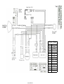
(17) Electrical Wires
All the electrical wires are either single-color or two-color and, with only a few exceptions, must be
connected to wires of the same color. On any of the two-color wires there is a greater amount of one color
and a lesser amount of a second color, so a two-color wire is identified by first the primary color and then
the secondary color. For example, a yellow wire with thin red stripes is referred to as a "yellow/red" wire;
it would be a "red/yellow" wire if the colors were reversed to make red the main color.
(18) Replacement Parts
When there is a replacement instruction, replace these parts with new ones every time they are removed.
These replacement parts will be damaged or lose their original function once removed.
(19) Inspection
When parts have been disassembled, visually inspect these parts for the following conditions or other
damage. If there is any doubt as to the condition of them, replace them with new ones.
Abrasion Crack Hardening Warp
Bent Dent Scratch Wear
Color change Deterioration Seizure
(20) Specifications
Specification terms are defined as follows:
"Standards" show dimensions or performances which brand-new parts or systems have.
"Service Limits" indicate the usable limits. If the measurement shows excessive wear or deteriorated
performance, replace the damaged parts.
http://mototh.com


1-6 GENERAL INFORMATION
General Specifications
Items
KLX250-D1, D2, D3, D4
Dimensions:
Overall length
2115 mm
Overall width 910 mm
Overall height
1220 mm
Wheelbase
1435 mm
Road clearance 320 mm
Seat height
925 mm
Dry weight 104 kg
Curb weight: Front
53 kg
Rear
59 kg
Fuel tank capacity
8 L
Engine:
Type 4-stroke, DOHC, 1-cylinder
Cooling system Liquid - cooled
Bore and stroke 72.0 x 61.2 mm
Displacement
249 mL
Compression ratio
11.0:1.
Maximum horsepower
23.5 KW(32 PS) @8500 r/min(rpm),
(US) 22.4 KW (30.5 PS) @8500 r/min (rpm)
Maximum torque
26.5 N-m(2.7 kg-m, 19.5 ft-lb) @7500 r/min(rpm),
(US) 25.3 N-m (2.6 kg-m, 19.0 ft-lb) @7500 r/min (rpm)
Carburetion system
Carburetor, KEIHIN CVK32
Starting system Primary kick
Ignition system
CDI
Timing advance Electronically advanced
Ignition timing
From 5° BTDC @1700 r/min (rpm) to
40° BTDC @3000 r/min (rpm)
Spark plug
NGKCR8E, NDU24ESR-N
Cylinder numbering method
-
Firing order
-
Valve timing:
Inlet
Open 22° BTDC
Close 62° ABDC
Duration 264°
Exhaust
Open 61°BBDC
Close 19° ATDC
Duration
260°
Lubrication system
Forced lubrication (wet sump)
Engine oil:
Grade
SE, SF or SG class
Viscosity SAE10W-40, 10W-50, 20W-40, or 20W-50
Capacity 1.5 L
http://mototh.com

GENERAL INFORMATION 1-7
Items
KLX250-D1, D2, D3, D4
Drive Train:
Primary reduction system:
Type
Reduction ratio
Clutch type
Transmission:
Type
Gear ratios: 1 st
2nd
3rd
4th
5th
6th
Final drive system:
Type
Reduction ratio
Overall drive ratio
Gear
2.863 (63/22)
Wet multi disc
6-speed, constant mesh, return shift
3.000 (30/10)
2.000(30/15)
1.500 (27/18)
1.250 (25/20)
1.050 (21 /20)
0.904 (19/21)
Chain drive
3.571 (50/14)
9.253 @Top gear
Frame:
Type
Caster (rake angle)
Trail
Front tire: Type
Size
Rear tire: Type
Size
Front suspension: Type
Wheel travel
Rear suspension: Type
Wheel travel
Brake type: Front
Rear
Tubular, semi double cradle
26.5°
107 mm
Tube, D752F(AS)(US) K490
80/100-21 51 M
Tube, D752(AS)(US) K695
100/100-18 59M
Telescopic fork (AS) (US) Telescopic fork (upside down)
290 mm (AS)(US) 285 mm
Swingarm (uni-trak)
280 mm
Single disc
Single disc
Electrical Equipment:
Headlight: Type
Bulb
Taillight
Alternator: Type
Rated output
Semi-sealed beam
12 V 30 W
12 V10W
Three-phase AC
Specification subject to change without notice, and may not apply to every country.
(AS): Australia Model
(US): U.S Model
http://mototh.com

1-8 GENERAL INFORMATION
Items
KLX250-E1, E2, E3
Dimensions:
Overall length
2135 mm, (FG)(NR) 2220 mm
(IT) 2170 mm
Overall width
870 mm
Overall height
1210 mm
Wheel base
1440 mm
Road clearance 300 mm
Seat height
890 mm
Dry weight 115 kg
Curb weight:
Front 60 kg
Rear
69 kg
Fuel tank capacity 8L
Performance:
Minimum turning radius 2.4 m
Engine:
Type 4-stroke, DOHC, 1-cylinder
Cooling system Liquid - cooled
Bore and stroke
72.0 x 61.2 mm
Displacement
249 mL
Compression ratio 11.0 : 1
Maximum horsepower 18.4 kW (25 PS) @8000 r/min (rpm),
(AR)9.5 kW (13 PS) @5000 r/min (rpm)
Maximum torque 22.5 N-m (2.3 kg-m, 16.6 ft-lb) @7500 r/min (rpm)
(AR)18.5 N-m (1.9 kg-m, 13.7 ft-lb) @4000 r/min (rpm)
Carburetion system
Carburetor, KEIHIN CVK34
Starting system
Primary kick
Ignition system CDI
Timing advance Electronically advanced
Ignition timing
5° BTDC @1300 r/min (rpm) to
35° BTDC @5000 r/min (rpm)
Spark plug
NGKCR8E, NDU24ESR-N
Cylinder numbering method
-
Firing order
-
Valve timing:
Inlet
Open 22° BTDC
Close
62°ABDC
Duration 264°
Exhaust
Open
61° BBDC
Close
19° ATDC
Duration 260°
Lubrication system
Forced lubrication (wet sump)
Engine oil:
Grade
SE or SF class
Viscosity
SAE10W-40,10W-50, 20W-40, or 20W-50
Capacity
1.5 L
http://mototh.com

GENERAL INFORMATION 1-9
Items
KLX250-E1, E2, E3
Drive Train:
Primary reduction system:
Type
Gear
Reduction ratio
2.863 (63/22)
Clutch type Wet multi disc
Transmission:
Type 6-speed, constant mesh, return shift
Gear ratios: 1st 3.000(30/10)
2nd
2.000 (30/15)
3rd 1.500(27/18)
4th 1.250 (25/20)
5th 1.050 (21 /20)
6th
0.904(19/21)
Final drive system:
Type Chain drive
Reduction ratio 3.000 (42/14)
Overall drive ratio
7.772 @Top gear
Frame:
Type Tubular, semi double cradle
Caster (rake angle)
26.5°
Trail 109 mm, (AS) 107 mm
Front tire: Type
Tube, DUN LOP D603
Size
3.00-21 51 P
Rear tire: Type
Tube, DUNLOP D603
Size 4.60-18 63P
Front suspension: Type
Telescopic fork (AS)Telescopic fork(upside down)
Wheel travel 290 mm (AS)285 mm
Rear suspension: Type
Swingarm (uni-trak)
Wheel travel
280 mm
Brake type:
Front Single disc
Rear
Single disc
Electrical Equipment:
Headlight: Type Semi-sealed beam
Bulb 12 V 60/55 W (quartz-halogen)
Tail/brake light 12 V 5/21 W
Alternator:
Type Three-phase AC
Rated output
14.5 A/14 V @7000 r/min (rpm)
Specifications subject to change without notice, and may not apply to every country.
(AR) : Austria Model (IT) : Italy Model
(AS) : Australia Model (NR) : Norway Model
(FG) : Germany Model
http://mototh.com

1-10 GENERAL INFORMATION
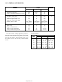
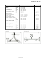
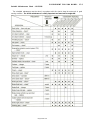
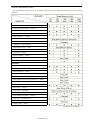
Periodic Maintenance Chart - KLX250D
The maintenance must be done in accordance with this chart to keep the motorcycle in good running
condition.
ENGINE
Clutch -- adjust
Clutch and friction plates -- check*
Throttle cables -- adjust
Spark plug -- clean, gap*
Valve clearance -- check*
Air cleaner element -- clean
Air cleaner element -- replace
Carburetor -- inspect/adjust
Spark arrester (US) -- clean
Oil filter -- replace
Engine oil -- change
Engine sprocket -- check*
Coolant -- change
Radiator hoses, connections -- check*
CHASSIS
Brake adjustment -- check*
Brake pad wear -- check*
Brake fluid level -- check*
Brake fluid -- change
Brake master cylinder cup and dust seal -- replace
Brake caliper piston seal and dust seal -- replace
Brake hose -- replace
Spoke tightness and rim runout -- check*
Drive chain -- adjust
Drive chain -- lubricate
Drive chain wear -- check*
Chain slipper and guide -- check*
Front fork -- inspect/clean
Front fork oil -- change
Steering play -- check*
Steering stem bearing -- grease
(Continued on next page.)
http://mototh.com

GENERAL INFORMATION 1-11
FFFRRREEEQQQUUUEEENNNCCCYYY
OOOPPPEEERRRAAATTTIIIOOONNN
Traveled Distance km (mi)
100
(60)
500
(300)
1000
(600)
1500
(900)
2000
(1200)
Rear sprocket -- check*
•
•
•
•
Wheel bearing -- check*
•
Swingarm and uni-trak linkage pivots -- grease •
•
•
•
Swingarm and uni-trak linkage pivots -- check*
•
•
•
•
Rear shock oil -- change Every year
ENGINE and CHASSIS
Fuel system -- clean • •
•
•
•
Fuel hose -- replace Every 4 years
Nuts, bolts, fasteners -- check*
•
•
•
General lubrication -- perform •
•
•
•
•
(*) : Replace, add, adjust, clean, or torque if necessary.
R : Replace
• : Service more frequently when operated in a race.
(US) : U.S. model
http://mototh.com

1-12 GENERAL INFORMATION
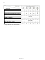
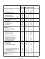
Periodic Maintenance Chart - KLX250E
The scheduled maintenance must be done in accordance with this chart to keep the motorcycle in good
running condition. The initial maintenance is vitally important and must not be neglected.
Spark plug -- clean and gap*
Valve clearance -- check*
Air cleaner element -- clean
Air cleaner element -- replace
Throttle grip play -- check*
Idle speed -- check*
Fuel system -- check*
Evaporative emission control system (CA)
-- check*
Spark arrester (US) -- clean
Engine oil -- change
Oil filter -- replace
Radiator hoses, connections-- check
Coolant -- change
Fuel hose -- replace
Clutch -- adjust
Drive chain wear - check*
Drive chain -- lubricate
Drive chain slack -- check*
Brake pad wear -- check*
Brake fluid level -- check*
Brake fluid -- change
Brake hose and pipe -- replace
Brake master cylinder cup and dust
seal -- replace
Caliper piston seal and dust seal
-- replace
Brake light switch --check*
Steering play -- check*
http://mototh.com

GENERAL INFORMATION 1-13
(t): For higher odometer readings, repeat at the frequency interval established here.
(*): Replace, add, adjust, clean, or torque if necessary.
(CA) : California Model
(US) : U.S. Model
Steering stem bearing -- lubricate
Front fork oil -- change
Tire wear -- check*
Spoke tightness and rim runout --
check*
Swingarm pivot, uni-trak linkage
-- lubricate
General lubrication -- perform
Nut, bolt, and fastener tightness -- check*
http://mototh.com
Page is loading ...
Page is loading ...
Page is loading ...
Page is loading ...
Page is loading ...
Page is loading ...
Page is loading ...
Page is loading ...
Page is loading ...
Page is loading ...
Page is loading ...
Page is loading ...
Page is loading ...
Page is loading ...
Page is loading ...
Page is loading ...
Page is loading ...
Page is loading ...
Page is loading ...
Page is loading ...
Page is loading ...
Page is loading ...
Page is loading ...
Page is loading ...
Page is loading ...
Page is loading ...
Page is loading ...
Page is loading ...
Page is loading ...
Page is loading ...
Page is loading ...
Page is loading ...
Page is loading ...
Page is loading ...
Page is loading ...
Page is loading ...
Page is loading ...
Page is loading ...
Page is loading ...
Page is loading ...
Page is loading ...
Page is loading ...
Page is loading ...
Page is loading ...
Page is loading ...
Page is loading ...
Page is loading ...
Page is loading ...
Page is loading ...
Page is loading ...
Page is loading ...
Page is loading ...
Page is loading ...
Page is loading ...
Page is loading ...
Page is loading ...
Page is loading ...
Page is loading ...
Page is loading ...
Page is loading ...
Page is loading ...
Page is loading ...
Page is loading ...
Page is loading ...
Page is loading ...
Page is loading ...
Page is loading ...
Page is loading ...
Page is loading ...
Page is loading ...
Page is loading ...
Page is loading ...
Page is loading ...
Page is loading ...
Page is loading ...
Page is loading ...
Page is loading ...
Page is loading ...
Page is loading ...
Page is loading ...
Page is loading ...
Page is loading ...
Page is loading ...
Page is loading ...
Page is loading ...
Page is loading ...
Page is loading ...
Page is loading ...
Page is loading ...
Page is loading ...
Page is loading ...
Page is loading ...
Page is loading ...
Page is loading ...
Page is loading ...
Page is loading ...
Page is loading ...
Page is loading ...
Page is loading ...
Page is loading ...
Page is loading ...
Page is loading ...
Page is loading ...
Page is loading ...
Page is loading ...
Page is loading ...
Page is loading ...
Page is loading ...
Page is loading ...
Page is loading ...
Page is loading ...
Page is loading ...
Page is loading ...
Page is loading ...
Page is loading ...
Page is loading ...
Page is loading ...
Page is loading ...
Page is loading ...
Page is loading ...
Page is loading ...
Page is loading ...
Page is loading ...
Page is loading ...
Page is loading ...
Page is loading ...
Page is loading ...
Page is loading ...
Page is loading ...
Page is loading ...
Page is loading ...
Page is loading ...
Page is loading ...
Page is loading ...
Page is loading ...
Page is loading ...
Page is loading ...
Page is loading ...
Page is loading ...
Page is loading ...
Page is loading ...
Page is loading ...
Page is loading ...
Page is loading ...
Page is loading ...
Page is loading ...
Page is loading ...
Page is loading ...
Page is loading ...
Page is loading ...
Page is loading ...
Page is loading ...
Page is loading ...
Page is loading ...
Page is loading ...
Page is loading ...
Page is loading ...
Page is loading ...
Page is loading ...
Page is loading ...
Page is loading ...
Page is loading ...
Page is loading ...
Page is loading ...
Page is loading ...
Page is loading ...
Page is loading ...
Page is loading ...
Page is loading ...
Page is loading ...
Page is loading ...
Page is loading ...
Page is loading ...
Page is loading ...
Page is loading ...
Page is loading ...
Page is loading ...
Page is loading ...
Page is loading ...
Page is loading ...
Page is loading ...
Page is loading ...
Page is loading ...
Page is loading ...
Page is loading ...
Page is loading ...
Page is loading ...
Page is loading ...
Page is loading ...
Page is loading ...
Page is loading ...
Page is loading ...
Page is loading ...
Page is loading ...
Page is loading ...
Page is loading ...
Page is loading ...
Page is loading ...
Page is loading ...
Page is loading ...
Page is loading ...
Page is loading ...
Page is loading ...
Page is loading ...
Page is loading ...
Page is loading ...
Page is loading ...
Page is loading ...
Page is loading ...
Page is loading ...
Page is loading ...
Page is loading ...
Page is loading ...
Page is loading ...
Page is loading ...
Page is loading ...
Page is loading ...
Page is loading ...
Page is loading ...
Page is loading ...
Page is loading ...
Page is loading ...
Page is loading ...
Page is loading ...
Page is loading ...
Page is loading ...
Page is loading ...
Page is loading ...
Page is loading ...
Page is loading ...
Page is loading ...
Page is loading ...
Page is loading ...
Page is loading ...
Page is loading ...
Page is loading ...
Page is loading ...
Page is loading ...
Page is loading ...
Page is loading ...
Page is loading ...
Page is loading ...
Page is loading ...
Page is loading ...
Page is loading ...
Page is loading ...
Page is loading ...
Page is loading ...
Page is loading ...
Page is loading ...
Page is loading ...
Page is loading ...
Page is loading ...
Page is loading ...
Page is loading ...
Page is loading ...
Page is loading ...
Page is loading ...
Page is loading ...
Page is loading ...
Page is loading ...
Page is loading ...
Page is loading ...
Page is loading ...
Page is loading ...
Page is loading ...
Page is loading ...
Page is loading ...
Page is loading ...
Page is loading ...
Page is loading ...
Page is loading ...
Page is loading ...
Page is loading ...
Page is loading ...
Page is loading ...
Page is loading ...
Page is loading ...
Page is loading ...
-
 1
1
-
 2
2
-
 3
3
-
 4
4
-
 5
5
-
 6
6
-
 7
7
-
 8
8
-
 9
9
-
 10
10
-
 11
11
-
 12
12
-
 13
13
-
 14
14
-
 15
15
-
 16
16
-
 17
17
-
 18
18
-
 19
19
-
 20
20
-
 21
21
-
 22
22
-
 23
23
-
 24
24
-
 25
25
-
 26
26
-
 27
27
-
 28
28
-
 29
29
-
 30
30
-
 31
31
-
 32
32
-
 33
33
-
 34
34
-
 35
35
-
 36
36
-
 37
37
-
 38
38
-
 39
39
-
 40
40
-
 41
41
-
 42
42
-
 43
43
-
 44
44
-
 45
45
-
 46
46
-
 47
47
-
 48
48
-
 49
49
-
 50
50
-
 51
51
-
 52
52
-
 53
53
-
 54
54
-
 55
55
-
 56
56
-
 57
57
-
 58
58
-
 59
59
-
 60
60
-
 61
61
-
 62
62
-
 63
63
-
 64
64
-
 65
65
-
 66
66
-
 67
67
-
 68
68
-
 69
69
-
 70
70
-
 71
71
-
 72
72
-
 73
73
-
 74
74
-
 75
75
-
 76
76
-
 77
77
-
 78
78
-
 79
79
-
 80
80
-
 81
81
-
 82
82
-
 83
83
-
 84
84
-
 85
85
-
 86
86
-
 87
87
-
 88
88
-
 89
89
-
 90
90
-
 91
91
-
 92
92
-
 93
93
-
 94
94
-
 95
95
-
 96
96
-
 97
97
-
 98
98
-
 99
99
-
 100
100
-
 101
101
-
 102
102
-
 103
103
-
 104
104
-
 105
105
-
 106
106
-
 107
107
-
 108
108
-
 109
109
-
 110
110
-
 111
111
-
 112
112
-
 113
113
-
 114
114
-
 115
115
-
 116
116
-
 117
117
-
 118
118
-
 119
119
-
 120
120
-
 121
121
-
 122
122
-
 123
123
-
 124
124
-
 125
125
-
 126
126
-
 127
127
-
 128
128
-
 129
129
-
 130
130
-
 131
131
-
 132
132
-
 133
133
-
 134
134
-
 135
135
-
 136
136
-
 137
137
-
 138
138
-
 139
139
-
 140
140
-
 141
141
-
 142
142
-
 143
143
-
 144
144
-
 145
145
-
 146
146
-
 147
147
-
 148
148
-
 149
149
-
 150
150
-
 151
151
-
 152
152
-
 153
153
-
 154
154
-
 155
155
-
 156
156
-
 157
157
-
 158
158
-
 159
159
-
 160
160
-
 161
161
-
 162
162
-
 163
163
-
 164
164
-
 165
165
-
 166
166
-
 167
167
-
 168
168
-
 169
169
-
 170
170
-
 171
171
-
 172
172
-
 173
173
-
 174
174
-
 175
175
-
 176
176
-
 177
177
-
 178
178
-
 179
179
-
 180
180
-
 181
181
-
 182
182
-
 183
183
-
 184
184
-
 185
185
-
 186
186
-
 187
187
-
 188
188
-
 189
189
-
 190
190
-
 191
191
-
 192
192
-
 193
193
-
 194
194
-
 195
195
-
 196
196
-
 197
197
-
 198
198
-
 199
199
-
 200
200
-
 201
201
-
 202
202
-
 203
203
-
 204
204
-
 205
205
-
 206
206
-
 207
207
-
 208
208
-
 209
209
-
 210
210
-
 211
211
-
 212
212
-
 213
213
-
 214
214
-
 215
215
-
 216
216
-
 217
217
-
 218
218
-
 219
219
-
 220
220
-
 221
221
-
 222
222
-
 223
223
-
 224
224
-
 225
225
-
 226
226
-
 227
227
-
 228
228
-
 229
229
-
 230
230
-
 231
231
-
 232
232
-
 233
233
-
 234
234
-
 235
235
-
 236
236
-
 237
237
-
 238
238
-
 239
239
-
 240
240
-
 241
241
-
 242
242
-
 243
243
-
 244
244
-
 245
245
-
 246
246
-
 247
247
-
 248
248
-
 249
249
-
 250
250
-
 251
251
-
 252
252
-
 253
253
-
 254
254
-
 255
255
-
 256
256
-
 257
257
-
 258
258
-
 259
259
-
 260
260
-
 261
261
-
 262
262
-
 263
263
-
 264
264
-
 265
265
-
 266
266
-
 267
267
-
 268
268
-
 269
269
-
 270
270
-
 271
271
-
 272
272
-
 273
273
-
 274
274
-
 275
275
-
 276
276
-
 277
277
-
 278
278
-
 279
279
-
 280
280
-
 281
281
-
 282
282
-
 283
283
-
 284
284
-
 285
285
-
 286
286
-
 287
287
-
 288
288
-
 289
289
-
 290
290
-
 291
291
-
 292
292
-
 293
293
-
 294
294
-
 295
295
-
 296
296
-
 297
297
-
 298
298
-
 299
299


Kawasaki KLX250-D3 User manual
- Category
- Motorcycles
- Type
- User manual
Ask a question and I''ll find the answer in the document
Finding information in a document is now easier with AI
Related papers
-
Kawasaki KLX250 D-Tracker X User manual
-
-
-
-
-
-
-
-
Kawasaki Ninja ZX-6R 2005 User manual
-
Other documents
-
 LT Sport 769553135125 for Toyota 14" (R14) Rim Skin Hubcap ABS 4pcs Wheel Cover User guide
-
DANCO 10763 Operating instructions
-
Pittsburgh Automotive Item 35555 Owner's manual
-
 BETTERCLOUD TR-600HP Snap-in High Pressure Tire Wheel Valve Stems (100 Pack) Installation guide
-
Baotian BT49QT-3 User manual
-
 Eco Flo SUP55 Operating instructions
-
 Eco Flo SUP58 Operating instructions
-
 Eco Flo EPC50 Installation guide
-
MasterCool GM A6/R4/DA6/V5 Seal Tool Kit 91269 Operating instructions
-
Everbilt 22111 Installation guide


