NEC NP1250 Owner's manual

Category
Data projectors
Type
Owner's manual

NEC NP1250 is a stacking correction tool software designed to assist in the alignment and calibration of multiple projectors for stacked projection applications. It allows users to easily create geometric correction data for stacked images, resulting in seamless and cohesive projections. By utilizing the [GEOMETRIC CORRECTION] function of NEC projectors, the NP1250 simplifies the process of aligning and adjusting projected images for events, conferences, and other large-scale presentations.

NEC NP1250 is a stacking correction tool software designed to assist in the alignment and calibration of multiple projectors for stacked projection applications. It allows users to easily create geometric correction data for stacked images, resulting in seamless and cohesive projections. By utilizing the [GEOMETRIC CORRECTION] function of NEC projectors, the NP1250 simplifies the process of aligning and adjusting projected images for events, conferences, and other large-scale presentations.

Stacking Correction Tool
User’s Manual
NEC Projector User Supportware
2
Terminology
In this manual, the term stacking correction is used to describe the following processes performed by the Stacking Correction
Tool.
1. Photographing the projected images of multiple projectors with a digital camera or a web camera
2. Perform comparisons and calculations so that the content of the projected images is superimposed, and create the
GEOMETRIC CORRECTION data
3. Send the [GEOMETRIC CORRECTION] data to each projector
NOTE
(1) Unauthorized reproduction of a part of or all of the content of this manual is prohibited.
(2) The content of this manual is subject to change without notice.
(3) Great care has been given to the creation of the content of this manual; however, should you notice any questionable
points, errors, or omissions, please contact us.
(4) Notwithstanding section (3), NEC will not bear any responsibility for claims due to loss, lost prot, or other matters for
reason of the use of this software.
Introduction
Thank you for using the Stacking Correction Tool.
Please read this User's Manual carefully to aid in the proper use of this product before using the Stacking Correction Tool.
• TheStackingCorrectionToolissoftwarethatusesthe[GEOMETRICCORRECTION]functionoftheNECprojectortoeasily
perform stacked projection.
3
Precautions in Projector Installation
• Pleasepayattentiontotheinstallationsothatthepositioningoftheventilationoutletandtheventilationinletofadjacent
projectors is not too close.
A projector taking in the exhaust of an adjacent projector will result in overheating or other faults.
• Donotphysicallystackprojectorsoneabovetheother.
Projectors that are physically stacked could fall causing damage and breakdown of the projectors.
Please read the projector User's Manual for other installation precautions.
Installation Example Using 2 Projectors
In consideration of using this software, we recommend an installation like the following when the installation combines 2 pro-
jectors.
Installation Examples
Left side
Front
Exhaust Intake
Ventilation inletVentilation outlet
Cabinet Cabinet Cabinet
Right side
Warning
• Pleaserequestceilingmountandotherspecialinstallationatyourstoreofpurchase.In-
stallationshouldneverbeundertakenbythecustomer.Doingsocouldresultintheprojec-
tors falling or in injury. A strong cabinet that will support the weight of the projectors should
beusedinthisinstallation.Donotstacktheprojectorsdirectlyoneupontheother.
• Pleaseseetheuser'smanualoftheprojectorforinformationabouttherangeofprojectiondistance.
• Leavesufficientspacetotheleftandrightoftheprojectorssothatthereisnoobstructionofprojectorairintake
and exhaust. Obstruction of air intake and exhaust will result in a rise of the internal temperature of the projector
and will cause breakdown.
Note
4
Restrictions on Projectors that Are to Be Installed
• Installallprojectorsonthesamenetwork.
• Setallprojectorstothesameresolution.
• Usethesamemodeltotheextentpossible.
* When there is a difference in the brightness of the projectors, the digital camera or web camera might not accurately
read the projection image at the time of calibration.
* Therewillalsobeadifferenceinbrightnessdependingonthesettingofthe[LAMPMODE];therefore,setthe[LAMP
MODE]toauniformsettingofeither[NORMAL]or[ECO]fortheprojectorsthatarebeinginstalled.
• Pleasenotethattheuseofthissoftwarefor[DESKTOPREAR]and[CEILINGREAR]projectorprojectionmethodsisnot
supported.
Application Environment of the Stacking Correction Tool
The following personal computer environment is recommended to provide convenient use of digital cameras or web cameras
when calibrating.
Windows Vista Windows XP
Pentium 4, 2.4 GHz (A processor of 2.8 GHz or higher is rec-
ommended)
512 MB RAM (1 GB or greater is recommended)
1 GB or more of free hard disk space
Pentium4,1.4GHz,orAMDAthlon1GHz(APentium4,2.4
GHZ processor or higher is recommended)
128 MB RAM (256 MB or greater is recommended)
1 GB or more of free hard disk space
Use of the Stacking Correction Tool should be performed by an "Administrator" for Windows Vista, and a "Computer
Administrator" for Windows XP.
Required Components
.NET Framework 3.5
DirectX9
Java (Version 6, update 7 or later)
Supported Equipment
Projector NP3250/NP2250/NP1250/NP3250W*
Digitalcamera
Canon EOS Rebel XSi (in North America)
CanonEOS450D(inGermany)
Web camera
LogitechQuickCam®Pro9000
Logitech QuickCam® Pro for Notebooks
* ThenumberofpixelsoftheLCDpanelofmodelNP3250Wdiffersfromthatoftheother3models;therefore,pleaseuse
model NP3250W projectors with others NP3250W projectors.
Supported Screens
Only at screens are supported. Curved screens are not supported.
Note also that proper calibration might not be possible for rear projection screens and other screens in which there is a large
difference in brightness between the center and peripheral areas.
Note
5
Steps up to Stacking Correction
Install the Stacking Correction Tool Page 7
Install and connect the computer, projector, digital camera, or web camera
Page 11
Install the Stacking Correction Tool
Page 14
Make adjustments to the projector, digital camera, or web camera
Projector preparation Page 18
Digitalcameraorwebcamerapreparation Page 19
Perform the Stacking Correction
Page 20
6
Table of Contents
Precautions in Projector Installation ................................................................ 3
Restrictions on Projectors that Are to Be Installed ......................................... 3
Application Environment of the Stacking Correction Tool .............................. 4
Steps up to Stacking Correction
......................................................................... 5
1. Installation of the Stacking Correction Tool ................................................. 7
Installing the Stacking Correction Tool ......................................................................
7
Uninstalling the Stacking Correction Tool ................................................................
10
2. Installation and Connection of Equipment ................................................. 11
Connections for Stacking Correction .......................................................................
11
Connections for Projecting an Image
................................................................
12
3. Stacking Correction Tool Settings .............................................................. 14
Starting the Stacking Correction Tool
...........................................................
14
Names of the Stacking Correction Tool Screen
............................................
14
Stacking Correction Tool Menu
....................................................................
15
Names of the Calibration Screen
..................................................................
16
4. Preparation of the Projectors...................................................................... 18
5. Preparation of the Digital Camera or Web Camera ................................... 19
6. Performing Stacking Correction ................................................................. 20
7. Calibration .................................................................................................... 23
8. List of Error Messages ................................................................................ 25
7
1. Installation of the Stacking Correction Tool
Preparation: Save the downloaded Stacking Correction Tool le to the desired location
* The same installation procedure is used for Windows Vista and Windows XP.
1. Double click SCTxxx.exe
The installation screen will be displayed.
Note
Java (version 6, update 7 or later) and .NET Framework 3.5 are required in
the use of the Stacking Correction Tool. If these terms have not been sat-
ised, the screen to the right will be displayed when starting SCTxxx.exe.
When [Install] is selected, a connection will be made with the Internet and
downloading of the required component les from the distribution source
site will begin.
When the download is completed, the setup program will start automati-
cally. Follow the instructions on the screen and complete the setup.
* When making a new installation of .NET Framework 3.5 on Windows
XP (i.e., an older version of .NET Framework has not been installed),
the required component files will have a size of about 63 MB (and
about 20 MB when using Windows Vista). It could take a considerable
time from the start of downloading to the completion of installation.
Also, if requested to restart Windows after installing .NET Framework
3.5, please follow the instructions and restart Windows. The installa-
tion of the Stacking Correction Tool will continue after restarting Win-
dows.
* If connection cannot be made with the Internet, use another computer
that can connect with the Internet and access the URL listed below,
then download the required component les and use them.
[Java]
http://www.java.com/en/
[.NET Framework 3.5]
http://msdn.microsoft.com/en-us/netframework/default.aspx
.NET Framework 3.5 Installation
Screen
Java Installation Screen
Installing the Stacking Correction Tool
8
1. Installation of the Stacking Correction Tool
2. Select "I accept the terms in the license agree-
ment" and click [Next].
Please read the content of the END USER LICENSE
AGREEMENT carefully.
A screen for verifying the installation location will be displayed.
3. Click [Next]
To change the installation location, click [Change] and specify
the installation location.
A screen notifying that the installation preparation has been
completed will be displayed.
4. Click [Install]
The installation will begin.
As the installation proceeds, installation will start for applica-
tions required in the operation of the Stacking Correction Tool.
5. Click [OK]
A screen for verifying the installation location will be displayed.
If a language selection screen is displayed, select the lan-
guageandclick[OK].
Note
9
1. Installation of the Stacking Correction Tool
DirectX9orlaterisrequiredintheuseofthisapplication.
If these terms have not been satised, the screen to the right will
be displayed.
Follow the instructions on the screen and complete the setup of
DirectX9.
6. Click [Install]
The installation will start.
To change the installation location, click [Browse] and specify
the installation location.
Note
DirectXInstallationScreen
7. Click [Close]
This completes the installation of the Stacking Correction Tool.
Click [Finish] on the screen and close the setup program.
10
Uninstallation of the Stacking Correction Tool
Windows Vista
Select the Stacking Correction Tool from [Uninstall a program] under [Control Panel] and uninstall it.
Windows XP
Select the Stacking Correction Tool from [Add/Remove Programs] under [Control Panel] and uninstall it.
1. Installation of the Stacking Correction Tool
11
2. Installation and Connection of Equipment
Connections for Stacking Correction
•Installthedigitalcameraorwebcamerafacingtheprojectionimage.
•Thephotographiccoverageofthedigitalcameraorwebcamerais3.
Note
•Connecteachoftheprojectorstothesamenetwork.
•UseLANcablethatsupportsCategory5orhigherfortheconnectiontothenetwork.
•Plugeachprojectorintoapoweroutlet.
WIRELESS
WIRELESS
WIRELESS
WIRELESS
COMPUTER1 IN
COMPUTER1 IN
To digital
connector
Computer (for stacking correction)
Projector
Projector
Projector
To USB port
To LAN port
LAN
Digital camera
Web camera
or
LAN LAN
12
2. Installation and Connection of Equipment
Connections for Projecting an Image
• Whentheprojectorsareconnectedwithadaisychainconnection,theRGBvideosignalwillbeattenuated
and its projection might not be possible. Use an RGB signal divider as illustrated in the above connection
diagram.
Note
MONITOR OUT
COMPUTER1 IN
MONITOR OUT
COMPUTER1 IN
To Computer 1 input
of the next projector
RGB output
connector of PC
DaisyChainConnection
WIRELESS
WIRELESS
WIRELESS
WIRELESS
WIRELESS
WIRELESS
COMPUTER1 IN
COMPUTER1 IN
VGA signal cable
VGA signal cable
VGA signal cable
Computer
Projector
Projector
Analog RGB signal divider
(Mini D-Sub 15 pin)
To displayed output
connector (Mini D-Sub 15 pin)
COMPUTER1 IN
Projector
Analog RGB output
Analog RGB input
12 3
RGB Signal
Reference
• ConnectionscanalsobemadeusingcommerciallyavailableBNCcable.
13
2. Installation and Connection of Equipment
Component output
Audio output
L
R
YCbCr
Projector
Component video cable
Projector Projector
DVD player
COMPONENT IN
DVD component
signal divider
COMPONENT IN COMPONENT IN
YCbCr YCbCr
YCbCr
YCbCr
Output1 Output2 Output3
Input
Makeconnectionsasillustratedinthediagramsbelowwhenconnectingvideoequipmentotherthanthecomputer(e.g.,DVD
players, S-video, etc.).
Audio output Video output
L
R
VIDEO S-VIDEO
Projector Projector Projector
DVD player / Video deck
S-video signal
divider
S-video cable S-video cable
S-video cable
S-video cable
S-VIDEO IN S-VIDEO IN S-VIDEO IN
1
S-video output
S-video input
23
Component Signal
S-video signal
Reference
• ConnectionscanalsobemadevianetworkusingImageExpressUtility2.0.
14
3. Stacking Correction Tool Settings
Starting the Stacking Correction Tool
The same Stacking Correction Tool starting method is used for Windows Vista and Windows XP.
Select the Stacking Correction Tool from [Start] [All Programs] [NEC Projector User Supportware] and start it.
Names of the Stacking Correction Tool Screen
Stacking Correction Tool Main Screen
List of Connected Projectors
Displaystheconnectionorder,IPaddress,projectorname,andresolutionforthecurrently
connectedprojectors.
DestinationofGeometricCor-
rectionData
Select settings 1 to 3 of the projector's [GEOMETRIC CORRECTION] onscreen menu
as the [GEOMETRIC CORRECTION] data storage location after stacking correction.
Calibration Mode
Master Projector:
Theprojectorthatwillserveasthemasterisdetermined,andthe projectionimageof
anotherprojectorundergoesstackingcorrectionsothatitisinagreementwiththepro-
jectionimageofthemasterprojector.
In this instance, the [GEOMETRIC CORRECTION] ofthemaster projector doesnot
change.
Auto:
Whenthereisascreenframe,theprojectionimageiscorrectedsoastotinsidethat
frame.
Whenthereisnoframe,correctionisappliedsothattheareaoftherectangleismaxi-
mizedwithinthesuperimposedportionoftheprojectionarea.
Theaspectratiooftheinputsignalisnotmaintainedatthistime.
[Next] Displaythecalibrationscreen.
( Page16)
[Exit]
ClosestheStackingCorrectionTool.
15
3. Stacking Correction Tool Settings
File
Open
Thisopens theGCXSle(with.gcxsextension)thatwas savedwith[Saveas]
andsendsthe[GEOMETRICCORRECTION]datatoeachoftheconnectedpro-
jectors.WhenusingaGCXSletoreproduceaprojectionthathasundergone
stackingcorrection,theinstallationandconnectionconditionofeachprojector
mustbethesameaswhentheGCXSlewassaved.
Whentherehasbeenachangeoftheprojectorconnectionorder,installationpo-
sition,projectionangle(includingtiltfootadjustment),projectionposition(including
lensshiftadjustment),orothersettings,projectionthathasundergonestacking
correctioncannotbereproduced.
Save as
*can be selected
whe n s tacking
c o r r e c t i o n i s
completed
Thisgathersthe[GEOMETRICCORRECTION]data,andtheconnectionorderof
eachprojectorandsavesitasstackingcorrectiondata(inaGCXSle).
Exit
ClosestheStackingCorrectionTool.
Options
Communication
Settings
The projectorsthat will beused in stacking correctionareselected with this
screen.Selectthetypeofnetwork(typeofNIC:networkinterfacecard)withthe
topmostpull-downmenu.
Connect
Detectsaprojectorthatisconnectedtothenetworkanddis-
playsitonalist.
Update
Updatesthelistdisplaywhentherehasbeenanincreaseor
decreaseof thenumberofnetwork projectors,when there
has beena changeinthetype of projector,or some other
change.
Input Address
SpeciesandsearchestheIPaddressoftheprojector.
Thesearchmethodcan beselectedfromthefollowingtwo
types.
• DirectinputandsearchingoftheprojectorIPaddress
• Specicationandsearchingofarange with startaddress
andendaddress
Edit List
Specifiesan address andregisterson a list theprojectors
thathavebeensearched.Thisalsopermitspostregistration
editinganddeletion,andadditionsandsearchesbyaddress
specication.
Camera Setting
Selectsthetypeofcamera.
Geometric Cor-
rection
Changes the geometric correction settings of the projector.
Help
Help
ThisdisplaysthehelpleoftheStackingCorrectionTool.
About
DisplaystheversionoftheStackingCorrectionTool.
Stacking Correction Tool Menu
16
3. Stacking Correction Tool Settings
Calibration Screen
Names of the Calibration Screen
Start Calibration
Startsthestackingcorrection
*
When using a web camera, clicking [Start Calibration] will start the utility software of
the web camera.
Camera Setup Performs the angle of view check and other camera checks.
Quit
DiscontinuesthecorrectionandreturnstotheStackingCorrectionTool.
Calibration Progress
Displaystheprogressofthecalibrationasapercentage.
17
3. Stacking Correction Tool Settings
Camera Setup Screen
Dependingonthecamera,itemsmarkedwith
C
might not function.
Take Another Picture
Takesaphotograph.
Gain
C
Adjuststhegainofthedigitalcamera.
Curent ISO Speed
C
Changes the ISO speed of the digital camera.
Curent Resolution
C
Adjuststheresolutionofthedigitalcamera.
Show Focus Pattern on Projector
Sendsa(15x15dot)testpatterntotheprojectorofthespeciednumber.
Thenumberofconnectedprojectorsisdisplayed.(Maximumof4.)
Zoom Out/Zoom In
C
Adjuststhezoomofthedigitalcamera.
Preview Screen
Thephotographsthathavebeentakenwillbedisplayed.
Either when using a digital camera or a web camera, set up so that
the projection image ts this preview screen.
Even though the projection image ts the preview screen of the utility
software supplied with the web camera, the projection image might
extend beyond the photographic range in the [Camera Setup] preview
screen.
If this occurs, adjust the position or angle of the web camera, take a
photograph with [Take Another Picture], and perform the setup while
checking.
When using a digital camera, the results of adjusting the gain, shutter speed, resolu-
tion, and zoom will be photographed automatically, and will be displayed on the pre-
view screen.
Finish
ClosestheCameraSetup.
Note
18
Note
4. Preparation of the Projectors
The projectors used in the stacking correction will now be prepared. Please refer to the user's manual of the projector in con-
junction with the description given in this manual.
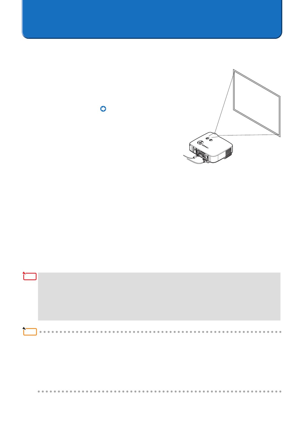
1. Install and connect the projectors that will be used,
and project them onto the screen (The portion of
projectors that will be used)
Connection of the Equipment Page 11
2. Adjust the Projectors
Refer to the projector user's manual and perform the following ad-
justments.
• Adjust sothattheprojectionimage ofeachprojectorentersthe
screen.
• Set[LAMPMODE]tothesamesettingforeachoftheprojectors.
• Makeimage qualityadjustments,projection position adjustments,andzoomandfocusadjustmentsas re-
quired.
• Whenperforming thestackingcorrection inconjunction with theprojectionscreenofthemaster projector,
performthe[CORNERSTONE]adjustmentfortheprojectorthatwillbethemaster.Iftheprojectionimageof
themasterprojectorisdistorted,stackingcorrectionwillbealsoperformedfortheotherprojectorsinconjunc-
tionwiththedistortedprojectionimage.
* Whentherehasbeenaselectionof[Bydetectingthemostextremecorners](i.e.,stackingcorrectionatthe
maximumallowablesize),the[CORNERSTONE]settingofalloftheprojectorswillberesetandtherewillbe
noneedtomakethesetting.
Reference
• Whenmakingsettingsonanumberofprojectors,itwillbeconvenienttousetheoptionalremotecontrol(NP02RC).Us-
ingtheprojector[CONTROLID]function,oneoptionalremotecontrolwillpermittheoperationofindividualprojectors,
ortheoperationofallprojectorsatonce.Pleaseseetheprojectoruser'smanualforinformationaboutthe[CONTROL
ID]setting.
• Settinga[PROJECTORNAME]toaprojectorinadvancewillaidinrecognitioneveninthelistdisplayedintheStacking
CorrectionTool[CommunicationSettings],andwillbeconvenientatthetimeofinstallation.
Pleaseseetheprojectoruser'smanualforinformationaboutthe[PROJECTORNAME]setting.
• The[CORNERSTONE]screenwillnotbedisplayedwhenmakingadjustmentswiththe[KEYSTONE]screen,or
whensetting[GEOMETRICCORRECTION].Toperformthe[CORNERSTONE]adjustment,holddownthe3DRE-
FORMbuttonfor2secondsorlonger,andclearthe[KEYSTONE]adjustmentvalues.
 Likewise,the[KEYSTONE]screenwillnotbedisplayedwhenmakingadjustmentswiththe[CORNERSTONE]
screen,orwhensetting[GEOMETRICCORRECTION].Toperformthe[KEYSTONE]adjustment,holddownthe
3DREFORMbuttonfor2secondsorlonger,andclearthe[CORNERSTONE]adjustmentvalues.
19
5. Preparation of the Digital Camera or Web Camera
The digital camera or web camera used in the stacking correction will now be prepared. Please refer to the user's manual of
the digital camera or web camera in conjunction with the description given in this manual.
1. Perform Settings of the Digital Camera or Web Camera that Will Be Used
Optimal camera settings will be made for the stacking correction.
Set the digital camera or web camera as described below.
Digital Camera
Setting Item Selection Notes
Mode dial on the digital camera body M
Select M (Manual exposure) from among the ve applicable
exposuremodesof A-DEP (automaticdepthofeldpriority
AE), M (manual exposure), Av (aperture priority AE), Tv (shut-
ter priority AE), and P (program AE).
Focus mode switch on the digital
camera body
MF
Select MF (manual focus) from among the two modes of AF
(automatic focus) and MF (manual focus).
Stabilizer switch on the digital cam-
era body
OFF Set the stabilizer switch to OFF.
Web Camera
Install the utility software that comes with the web camera and after startup, perform the settings as described
below.
Setting Item Selection Notes
Webcam
Settings
Focus [Manual Focus] Change to [Manual Focus] when [Auto Focus] is selected.
White Balance Manual Uncheck the "Auto" check mark.
Use Automatic RightLight™ Settings Off
Uncheck the "Use Automatic RightLight™ Settings" check
mark.
Advanced
Settings
Exposure/Gain
adjustment
Manual Uncheck the "Use Automatic Settings" check mark.
Anti Flicker [Off]
Select Off from among Off, 50 Hz (Europe), and 60 Hz (North
America).
LEDControl [Off] Select [Off] from among [Off], [On], and [Automatic].
2. Make a Connection to the Computer
Using the USB Cable
Connection of the Equipment Page 11
* Use the USB connection cable that comes
with the digital camera or the web camera.
To the USB port of the computer
20
6. Performing Stacking Correction
The stacking correction will be performed after completion of the connections of the projectors, digital camera or web camera,
and the computer.
1. Start the Stacking Correction Tool
2. Select the Projectors
Select [Communication Settings] of the [Options]
menu, then select the network type, enter
a check mark for the projectors that will be used,
click [Connect], and add to the list.
*Uptoamaximum of4projectorscanbeusedin
stackingcorrection.
4. Select the [GEOMETRIC CORRECTION]
data storage location
The default setting is [1].
In the projector, GEOMETRIC CORRECTION
data has already been registered in 1 to 3 as the
default setting.
The existing GEOMETRIC CORRECTION data
of the selected number will be overwritten in the
saving location by the Stacking Correction Tool.
Note
3. Select the Camera
Select the camera type with [Camera Setting] un-
der [Options].
1 / 1

NEC NP1250 Owner's manual

Category
Data projectors
Type
Owner's manual

NEC NP1250 is a stacking correction tool software designed to assist in the alignment and calibration of multiple projectors for stacked projection applications. It allows users to easily create geometric correction data for stacked images, resulting in seamless and cohesive projections. By utilizing the [GEOMETRIC CORRECTION] function of NEC projectors, the NP1250 simplifies the process of aligning and adjusting projected images for events, conferences, and other large-scale presentations.

Ask a question and I''ll find the answer in the document

Finding information in a document is now easier with AI

Ask the document