Page is loading ...


Safeguards are designed into this application equipment to protect operators and maintenance personnel from
most hazards during equipment operation. However, certain safety precautions must be taken by the operator
and repair personnel to avoid personal injury, as well as damage to the equipment. For best results, application
equipment must be operated in a dry, dust–free environment. Do not operate equipment in a gaseous or
hazardous environment.
Carefully observe the following safety precautions before and during operation of the equipment:
ALWAYS wear appropriate ear protection.
ALWAYS wear approved eye protection when operating powered equipment.
ALWAYS keep guard(s) in place during normal operation.
ALWAYS insert power plug into a properly grounded receptacle to avoid electrical shock.
ALWAYS turn off the main power switch and disconnect electrical cord from the power source when
performing maintenance on the equipment.
NEVER wear loose clothing or jewelry that may catch in moving parts of the application equipment.
NEVER insert hands into installed application equipment.
NEVER alter, modify, or misuse the application equipment.
The Tooling Assistance Center offers a means of providing technical assistance when required.
In addition, Field Service Specialists are available to provide assistance in the adjustment or repair of the
application equipment when problems arise which your maintenance personnel are unable to correct.
When calling the Tooling Assistance Center regarding service to equipment, it is suggested that a person
familiar with the device be present with a copy of the manual (and drawings) to receive instructions. Many
difficulties can be avoided in this manner.
When calling the Tooling Assistance Center, be ready with the following information:
01. Customer name
02. Customer address
03. Person to contact (name, title, telephone number, and extension)
04. Person calling
05. Equipment number (and serial number if applicable)
06. Product part number (and serial number if applicable)
07. Urgency of request
08. Nature of problem
09. Description of inoperative component(s)
10. Additional information/comments that may be helpful

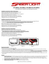
Figure 1
AMP–TAPETRONIC Machines No. 69875 and 69875–1 (see Figure 1) were designed to crimp a variety of
tape–mounted products onto solid and stranded wires from No. 26 through No. 8 AWG by using replaceable
die sets.
The AMP–TAPETRONIC machines consist of a basic AMP–O–LECTRIC* Model “K” Terminating Machine and
the application tooling required to crimp PIDG* and PLASTI–GRIP* Terminals and Splices, AMPLI–BOND*
Terminals, DIAMOND GRIP* Terminals, STRATO–THERM* Terminals and Closed End Splices. See Figure 2.
This manual pertains to the applicator portion of the AMP–TAPETRONIC machine. For information about the
Model “K” AMP–O–LECTRIC machine, refer to Customer Manual 409–5128. For information beyond the scope
of these manuals, contact the Tooling Assistance Center at 1–800–722–1111.
Read this manual thoroughly before operating the machine. The performance of this machine will depend
largely upon the intelligent use of of the information contained in this manual.
When reading this manual, pay particular attention to DANGER, CAUTION, and NOTE statements.

Figure 2
Dimensions in this manual are in metric units [with U.S. customary equivalents in brackets.] unless otherwise
specified. Refer to Figure 3 for dimensions and specifications.
Reasons for revision to this manual are provided in Section 10, REVISION SUMMARY.
Interchangeable crimping dies are available for crimping terminals and butt splices on solid and stranded
wires ranging from No. 26 through No. 8 AWG. Dies, terminals, and splices are color–coded for a given
wire range. Products must be crimped in dies that carry the same color code dot. Refer to the instructions
packaged with the dies for terminal and splice crimp inspection procedures, maintenance/inspection
procedures, and parts replacement information.
When crimping Closed–End Splices and Spare Wire Caps, the foot switch must be depressed and
released for each cycle of machine operation. Dies for closed end splices are supplied with a lower tool
holder, a wire stop, and an extractor to replace the wire funnel. Dies for spare wire caps are supplied with
a lower tool holder and stop.
Refer to Section 8 for die replacement procedures for terminal and butt splice dies, and for machine
conversion procedure when converting to run closed end splices and spare wire caps. Refer to Section 7
for any adjustments that may be necessary.

Figure 3
The wire funnel permits easier and faster wire entry into product wire barrels prior to the crimping
operation, and it acts as an extractor by sweeping the crimped product out of the die closure after
crimping. Wire Funnel No. 68299–1, for wire range 22 through 14 AWG, is installed on the machine at the
factory. Wire Funnel No. 68306–1, for wire range 12 and 10 AWG, must be ordered separately. Refer to
Section 8 for replacement procedure.
An electric counter may be connected to the machine electrical system as shown in the wiring diagram in
Section 2. The counter must be supplied by the customer. The customer must ensure that the counter
voltage is of the correct rating.

Added to a basic AMP–O–LECTRIC Model “K” Terminating Machine is a linkage which actuates the indexing
mechanism from front to back during each cycle of operation. This action pulls the tape from the product and
raises the wire stop assembly to allow for removal of the crimped product by the wire funnel (or extractor).
Linkage attached to the mechanical feed on the machine operates a ratchet which advances the tape feed belt
one increment during each cycle of operation. This positions the product in the crimping dies. In the standby
condition, the machine ram is lowered to the holding position to retain the product during wire insertion and
crimping.
Figure 4
The applicator is enclosed in guards for personnel protection.
Refer to Customer Manual 409–5128 for the functional description of the basic AMP–O–LECTRIC
machine.
At the beginning of a machine cycle, the flywheel is rotating, the ram is in the neutral or holding position,
and a product is in the crimping position. When the foot switch is depressed, the machine solenoid is

energized, cycling the machine one revolution. The upper die will bottom to crimp the product. At the same
time, the indexing mechanism is retracted and the wire stop assembly is raised by the mechanical linkage
to the machine transmission.
After the product is crimped, the machine ram begins to raise the upper tooling and the indexing
mechanism moves forward. As the ram continues the upward stroke, linkage to the machine mechanical
feed is actuated to ratchet the tape feed belt forward one increment to position the next product in the
crimping area. In addition, the wire funnel is actuated to eject the crimped product from the lower die.
As the machine ram reaches the end of the upward stroke and begins the downward stroke to return to
the neutral or holding position, the wire funnel retracts to align with the product wire barrel for the next
cycle of operation.
Figure 5
The machine is operated by a foot switch. The foot switch must be depressed and released to perform
each cycle of operation. For further information, refer to the wiring diagram in Figure 6 and the electrical
schematic in Figure 7.

Figure 6

Figure 7

The machine is thoroughly inspected during and after assembly. Before it is shipped, final tests and inspections
are made to ensure proper functioning. Still, the following inspection should be performed as a safeguard
against problems generated during shipment.
1. Carefully uncrate the machine and place it on a sturdy bench where there is enough light to permit a
careful examination.
2. Thoroughly inspect the entire machine for evidence of damage that may have occurred during transit.
If the machine is damaged, file a claim against the carrier and notify Tyco Electronics immediately.
3. Check all components and parts to be certain they are secure.
4. Check all wiring for loose connections and for frayed or broken wire and insulation.
5. If applicable, check all air lines for evidence of loose connections or leaks.
The location of the machine in relation to the operator is essential to both safety and efficiency. Studies have
repeatedly shown that fatigue will be reduced and efficiency increased if particular attention is paid to the
bench, the operator’s chair, and the placement of the foot switch if one is used.
A sturdy bench, 711 to 762 mm [28 to 30 in.] high, aids comfort by allowing the operator’s feet to rest on
the floor. The operator’s weight and leg position can be easily shifted. The bench should have rubber
mounts to reduce noise. The open area under the bench should allow the chair to slide far enough in for
the operator’s back to be straight and supported by the back rest.
The machine should be located near the front of the bench and the tooling area (the area where product is
applied) should be 152 to 203 mm [6 to 8 in.] from the front edge. Access to the back of the machine must
be provided.
The operator’s chair should swivel, and the seat and back rest should be padded and independently
adjustable. The back rest should be large enough to support the back both above and below the waist.
In use, the chair should be far enough under the bench so that the operator’s back is straight and
supported by the back rest.
When the operator is correctly positioned in front of the machine, the foot should rest on the switch
comfortably and easily. The switch should be placed on a rubber mat. This allows the switch to be
movable and permits the operator to shift positions to minimize fatigue. At the same time the mat prevents
the switch from sliding unintentionally.
The preference for locating the switch varies among operators. Some like the switch located so that their
foot rests on the switch when their legs are in the natural sitting position (calf perpendicular to the floor).
Others prefer it slightly in front of the natural position. The important thing is that the foot be about 90 to
the calf when resting on the switch. Those who prefer the switch slightly forward may require a
wedge–shaped block placed under it.

Figure 8
Figure 9
Figure 8 shows proper location and position for foot and switch.
Figure 9 shows a typical layout for the efficient handling of materials.
This machine is installed in the same manner as described in Customer Manual 409–5128. If the reel holder is
to be used, attach it with the same two screws that secure the guard to the right side of the machine frame as
shown in Figure 10,A. If a magazine holder is required, it must be ordered separately, then installed on the
bench with bolts or screws approximately 101 mm [4 in.] from the left side of the machine as shown in
Figure10,B.
During normal operation, the machine stops with the ram down (in “holding” position). The machine must be
hand–cycled on occasion for various adjustments. Hand–cycle the machine as follows:

Figure 10
1. Unlatch and open flywheel cover on rear of machine.
2. Make sure the tape release lever is in the “down” position. See Figure 11.
3. Raise the stop bar, located below the solenoid, and turn the flywheel in the direction of arrow to cycle
the machine. The clutch will release at the end of the cycle.
4. Repeat Step 3 as necessary to complete the operation being performed.

Figure 11
1. Loosen the reel disk thumbscrew and remove the disk. See Figure 12.
2. Position reel so that terminal wire barrels face the rear of machine, then slide reel onto reel support
pin.
3. Replace reel disk and lock by tightening the thumbscrew.
4. Facing the front of the machine, twist the tape counterclockwise 180 so terminals are on top of tape
and wire barrels face the operator’s position. Feed tape through side guard and into indexing
mechanism.
5. Position first product in tape a few positions to the left of the crimping area. MAKE SURE feed
notches in tape engage with teeth on feed belt.
6. Adjust terminal guide to feed product straight into the crimping dies as shown in Figure 12.

Figure 12
7. Lower tape release lever to secure tape in position.
8. Connect the machine power supply and place the main power switch in the “ON” position.
9. Depress and release the foot switch as many times as necessary to index the first product into the
crimping area.
10. Replace the front guard before beginning production operation of the machine.
1. Remove front guard and raise tape release lever.
2. Remove tape from indexing mechanism.
3. Cut excess lead from tape and discard.
4. Secure end of tape to reel with masking tape.
5. Remove reel from reel support.

Figure 13
1. Check the machine to ensure that correct dies are installed. If necessary, refer to Section 8 for die
replacement procedure. To convert the machine to run closed–end splices or spare wire caps, refer to
the conversion procedure in Section 8.
2. Strip wire ends to length specified in the instruction material packaged with the dies.
3. With the machine connected to the power supply, place the main power switch in the ON position.
4. Insert the pre–stripped wire into the product wire barrel until the wire end contacts the internal wire
stop. See Figure 13. Depress and release the foot switch to cycle the machine.
5. Remove the crimped product and inspect for proper crimping. Refer to the crimp inspection procedure
packaged with the dies.
6. Repeat Steps 4 and 5 until the desired number of terminations has been made.
7. Upon completion, place the main power switch in the OFF position. If it is not to be used in the near
future, DISCONNECT MACHINE FROM THE POWER SUPPLY.
Products not crimped onto wire are difficult to remove from crimping dies. To prevent terminal jams during
setup and maintenance procedures,
always
insert a wire into the product wire barrel when crimping.
Product may also jam or pile up in the moving die if vertical movement of the wire stop is out of adjustment.
Refer to Section 7 for any adjustments that may be necessary.

Remove a jammed product as follows:
1. Remove front guard and raise the tape release lever.
2. Remove jammed product from crimping dies.
3. Visually inspect the die crimping surfaces for flattened, broken, or chipped conditions. Worn or
damaged crimping surfaces are objectionable and can affect the quality of the crimp. Refer to Figure 14
for examples of possible damage.
Figure 14
4. If necessary, replace dies as described in Paragraph 8.1.
5. After problem is corrected, replace the front guard and lower the tape release lever before continuing
operation.
It is important that a preventive maintenance program be performed at regular intervals to ensure efficient,
dependable performance of the machine. The preventive maintenance program consists of cleaning, visual
inspection, and lubrication.
Clean the dies daily. Do not allow deposits of dirt to build up on bottoming surfaces and die closure surfaces.

Except in abnormally dusty and dirty conditions, it will be necessary to clean the machine only when it is
disassembled for repairs. Wash the parts in solvent and dry thoroughly. Lubricate machine as instructed in
Paragraph 5.3 before placing it back in service.
Perform an
overall
visual inspection of the machine at least once a month, prior to performing the monthly
lubrication program (Paragraph 5.3).
1. Starting at the front and moving clockwise around the machine, check tightness of all mounting
screws and electrical connections. Check tightness of crimping die mounting screws at least twice daily.
2. Inspect all moving parts for excessive wear. The presence of metal particles indicates a need for
lubrication or a need to align parts.
3. Inspect the motor mounting screws, the connecting rod retainer nuts, and the flywheel and
main–shaft retaining ring.
4. Check for loose or missing cowling pins and retaining rings on transmission.
The moving components in the machine require regular lubrication to ensure reliable service. Use the
lubrication chart in Figure 16 as a guide to establish a lubrication schedule suited to your operating conditions
and for identification of lubrication points.
Refer to the lubricant specification chart, in Figure 15, for specific lubricant requirements.
If the machine has not been used for several days, it is a good policy to lubricate it before starting operation.
Figure 15

Figure 16 (cont’d)
G
O
O

Figure 16 (end)
G
O
G
O
O
O
G
O
G
G
O
O
G

Careful observance of the preventive maintenance program will reduce the possibility of machine malfunctions.
Refer to the electrical schematic, wiring diagram, and exploded views and parts lists for parts identification.
In the event of a machine malfunction, perform the following six–point visual inspection before attempting a
detailed troubleshooting procedure. If the visual inspection does not reveal the cause of the malfunction, then
refer to the troubleshooting chart.
1. Make sure the tape release lever is all the way down.
2. Be sure that the machine is connected to a properly grounded power supply (appropriate to the
machine, 115 Vac for 69875; and 230 Vac for 69875–1).
3. Inspect for burnt or loose electrical connections.
4. Inspect the machine for worn or damaged mechanical components.
5. Inspect all lubrication points for excessive build–up of lubricants or dirt.
6. Inspect for insufficient lubrication.
A troubleshooting table can be found in Figure 17.
/