Page is loading ...

Technical Data PR202-50-502-22
Effective June 2017
Supersedes April 2016
CF2000 System
Installation Manual

2
Technical Data PR202-50-502-22
Effective June 2017
CF2000 System
EATON www.eaton.com
Contents
Introduction to the Manual ..................3
Notice
.................................3
System Installation and Design
...............4
Introduction
............................4
Project Planning
.........................5
System Design Guidelines
.................5
Compatible Equipment
...................6
Interfaces
............................. 12
Equipment Compatibility ................. 16
System Overview ........................ 17
Simple user interface .................... 17
User configuration and maintenance facilities . 17
Spur tolerant soft addressing .............. 17
Technical Specification ..................... 18
Optional Functions as per EN54 Parts 2 & 4 .. 20
Installation .............................. 21
Mains Supply .......................... 21
Cable Segregation ...................... 21
Panel Installation ....................... 21
Fixing details .......................... 22
System Wiring ......................... 23
Commissioning CF2000 ................... 24
Up/downloading using PC software ......... 24
Device input programming ................ 25
Device Outputs ........................ 26
Panel Outputs ......................... 27
Panel Fault Finding ...................... 28
Protocol Format ........................ 30
Panel Controls and Indicators ............... 31
Panel Overview ........................ 30
System Healthy ........................ 31
View Event ............................ 32
Fire Event ............................. 33
View Fires ............................ 34
View Pre-Alarm ........................ 35
View Fault ............................ 36
View Disabled Address .................. 37
View Disabled Zone ..................... 39
View Disabled I/O ...................... 40
View Log ............................. 41
Operations (Soft Reset) .................. 42
Operations (Evacuate) ................... 43
Operations (Silence Alarms) ............... 44
Operations (Lamp Test) .................. 45
Operations (Weekly Test) ................. 46
Access Level 2 .......................... 47
Commissioning ........................ 47
Panel Settings (Erase Log) ................ 48
Panel Settings (Change Password) ......... 49
Panel Settings (Change Language) ......... 50
Panel Settings (Date/Time) ................ 51
Panel Setting-s (System Details) ........... 52
Testing (Test Device) .................... 53
Testing (Test Zone) ...................... 54
Testing (Test Sound Levels) ............... 55
Testing (One Man Walk Test) .............. 56
Testing (Global Flashing LED) screen ........ 57
Testing (Analogue Levels) ................ 58
Device Config (Add Device) ............... 59
Device Config (Delete Device) ............. 60
Device Config (Configure zones) ........... 61
Appendix ............................... 62
System Wiring ......................... 62
Sounder Base Wiring .................... 63
Call Point ............................. 64
Base Sounder Wiring .................... 65
Loop Powered Beacon ................... 66
Internal Wall Sounder .................... 67
IP66 Wall Sounder ...................... 68
3 Way Input/Output Unit ................. 69
1 Way Input/Output Unit ................. 70
Zone Monitor Unit Wiring ................ 71
Intrinsically Safe Zone Monitor Unit ......... 72
Shop Monitor Unit ...................... 73
Spur Isolator ........................... 74
4 Way Sounder Controller ................ 75
Micro Zone Monitor Unit ................. 76
Micro Input Module ..................... 77
Battery Disposal Instructions .............. 78
CE Marking ........................... 79

3
Technical Data PR202-50-502-22
Effective June 2017
CF2000 System
EATON www.eaton.com
Introduction to the Manual
This manual provides information on the installation, operation and
maintenance of the Cooper Fire Systems CF2000 System.
Notice
The operating system of the CF2000 may be revised as a result of
enhancements to the system software or hardware. An updated
issue of this manual is available on request. The current issue of
the manual can also be downloaded from the Eaton website.
WARNING
RISK OF EXPLOSION IF BATTERY IS REPLACED BY AN
INCORRECT TYPE DISPOSE OF THE USED BATTERIES
ACCORDING TO THE INSTRUCTIONS IN THE BATTERY
DISPOSAL INSTRUCTIONS.

4
Technical Data PR202-50-502-22
Effective June 2017
CF2000 System
EATON www.eaton.com
System Installation and Design
Introduction
CF2000 provides all of the sophisticated features required of a
leading edge analogue addressable fire system along with the
simple operation and neat installation demanded by installers and
building users.
The panel can be flush or surface mounted and the generously
sized metal back box allows ample facilities for rear or top cable
entries. It is available as a two loop panel.
A comprehensive range of ancillary devices is available to operate
with the CF2000 panel, including Optical, photo-thermal and heat
sensors, callpoints and a comprehensive range of interfaces.
Each of the CF2000 system components has been specifically
designed to operate as part of a CF2000 system, this provides
an assurance that the panel, the sensor, the interfaces and the
ancillaries are all fully compatible with each other and that the full
range of system functionality is supported by each device.
Each loop of a CF2000 panel can accommodate up to 200 (99
Belgium) addresses.

5
Technical Data PR202-50-502-22
Effective June 2017
CF2000 System
EATON www.eaton.com
Project Planning
The following is a typical program and timetable for a CF2000
installation project, once the initial order has been received:
1. Project Meeting
Installer and user to be present; system specifications, schematic
diagram and proposed circuit drawing to be available. CF2000
Installation & Commissioning Guide to be provided.
2. Equipment Fix
Typically 2 week's notice is required for equipment to be deliv-
ered. Cable to be installed and bases/back boxes to be fitted. Then
fire sensors, call points, alarm sounders and interface units can
installed.
3. Address Schedule
Schedule of sensor locations to be completed by installer and
returned to enable System programming.
4. Auto Learn
Fire panel/repeater panels to be installed and terminated. System
to be powered up by installer and auto learn mode activated (see
Auto Learn section). System to be tested and verified by installer,
prior to final commissioning.
5. Final Commissioning
Minimum 2 weeks notice is required from receipt of Address
Schedule and Commission request form for an Eaton Fire Systems
Service Engineer to attend site to implement/oversee the final
commissioning procedures (see Commissioning section), in
conjunction with the installer.
System Design Guidelines
Guidelines
Systems should conform to the relevant local standards and codes
of practice. For the UK this is BS5839 part 1. CF2000 meets all the
relevant requirements of BS5839 part 1: 2002.
Installation planning is simplified by the fact that every address-
able CF2000 device contains an integral short circuit isolator. Care
must be taken to ensure that local standards requirements regard-
ing aspects such as loop coverage, area covered by a single spur
and cable specification are observed.
There may be certain applications in which deviations from the
code may be necessary and these must be listed on the commis-
sioning certificate (see Commissioning CF2000).
Loop lengths
The maximum permitted loop length is 2 km measured from the
near to the far terminals on the CF2000 Motherboard PCB. There
is no minimum limit to loop length. Any wiring spurs off the loop
must be included within the 2 km limit. On long loop runs, the
lengths of wiring rises and falls (between floors, down to manual
call points) must be included. Remember to include these espe-
cially when taking loop lengths from plan drawings.
Loop loading - total number of addresses
The total number of addresses per loop is 200 (99 Belgium). This
includes detectors, call points and all other addressable items
and call points. When designing systems its recommended that
allowances are made for future expansion, Short circuit isolators
are incorporated into every CF2000 loop device, including Smoke
detectors, heat detectors, sounders, callpoints and interfaces.
Therefore, no further fault protection is required. In the event of a
single fault, none of the devices connected to the loop will fail to
operate as the fault will be isolated by the two adjacent devices.
Spur connected devices downstream of a cable fault will cease to
function.

6
Technical Data PR202-50-502-22
Effective June 2017
CF2000 System
EATON www.eaton.com
Compatible Equipment
Order code Reference Description Dimensions (mm)
CF2000GCPD CF2000GCPD 2 Loop CF2000 Panel 400H x 320W x 170D
CF3000PRG CF3000PRG Loop Passive repeater for CF2000 270H x 332W x 92D
400002FIRE-0002X CAP320 Addressable Optical Sensor (CAP320) 101 Dia x 33D
400003FIRE-0003X CAH330 Addressable Heat Sensor (CAH330) 101 Dia x 33D
400004FIRE-0004X CAPT340 Addressable Photo Thermal Sensor (CAPT340) 101 Dia x 33D
MAB50R-EM MAB50R Addressable Beam Detector (50m) 210H x 130W x 120D
MAB100R-EM MAB100R Addressable Beam Detector (100m) 210H x 130W x 120D
CAB300 CAB300 Addressable Sensor Base 104 Dia x 22D
666027FULL-0065X CAS380 Addressable Sounder Base 120 Dia x 40D
666098FULL-0153 CAS380AU Addressable Australian Sounder Base 120 Dia x 40D
CASBB384 CASBB384 Addressable Sounder Beacon Base 115 Dia x 44D
CASBB384-B CASBB384-B Addressable Bell Tone Sounder Beacon Base 115 Dia x 44D
CASBB394 CASBB394 Addressable VAD Sounder Beacon Base 115 Dia x 44D
600107FUL-0012 CIR301 Conventional Remote Indicator (Connects to Detector) 87H x 87W x 30D
CIR301WP CIR301WP Conventional Weatherproof Remote Indicator (Connects to
Detector)
87H x 87W x 30D
MRIAD MRIAD Addressable Remote Indicator 87H x 87W x 49D
4950010MEN-0432X CBG370S Addressable Callpoint 87H x 87W x 57D
4950 012FUL- 0 4 31X CBG370WP Addressable Weatherproof Callpoint 87H x 87W x 59D
654014FULL-0067X CAS381 Addressable Wall Sounder 105H x 105W x 95D
65 4 013FULL- 00 6 6X CAS381WP Addressable Weatherproof Wall Sounder 108H x 109W x 103D
65 4 0 41FUL L- 02 3 0 CAS381AU Addressable Australian Wall Sounder 105H x 105W x 95D
666101FULL-0156 CAS381AU-WP Addressable Australian Weatherproof Wall Sounder 108H x 109W x 103D
666028FULL-0066 CAB382 Addressable Beacon 95 Dia x 53D
666043FULL-0077X CASB383 Addressable Wall Sounder Beacon 105H x 105W x 95D
666044FULL-0078X CASB383-WP Addressable Weatherproof Wall Sounder Beacon 108H x 108W x 103D
666130FULL-0199X CASB393 Addressable Wall VAD Sounder Beacon 105H x 105W x 95D
666131FULL-0200X CASB393WP Addressable Weatherproof Wall VAD Sounder Beacon 108H x 108W x 103D
CSC354CPR CSC354CPR Addressable 4-Way Sounder Controller 300H x 300W x 74D
CZMU352 CZMU352 Addressable Zone Monitor Unit 88H x 147W x 57D
CZMU352-IS CZMU352-IS Addressable Zone Monitor Unit (Intrinsically Safe) 88H x 147W x 57D
MSU840 MSU840 Addressable Shop Unit Monitor 88H x 147W x 57D
CSI350 CSI350 Addressable Spur Isolator 88H x 147W x 57D
CMIO353
CMIO353 Addressable Mains Relay 130H x 180W x 60D
CIO351 CIO351 Addressable 3 Channel I/O Unit (Reset on Reset) 130H x 180W x 60D
400012FIRE-0026X MCOM-S Addressable Micro Output Unit (recognised as sounder) 65H x 35W x 18.5D
400010FIRE-0024X MCOM Addressable Micro Output Module (MCOM) 65H x 35W x 18.5D
400008FIRE-0022X MCIM Addressable Micro Input Module (MCIM) 65H x 35W x 18.5D
MIU872 MIU872 Addressable Micro Zone Monitor Unit 65H x 35W x 18.5D
ZPCB2252-MML ZPCB2252-MML Addressable Master LED MIMIC 190H x 350W x 75D
ZPCB2252-MSL ZPCB2252-MSL Addressable Slave LED MIMIC 190H x 350W x 75D

7
Technical Data PR202-50-502-22
Effective June 2017
CF2000 System
EATON www.eaton.com
Compatible Equipment
The range of compatible detectors for the CF2000 system
consists of the following:
Model CAP320 CAH330 CAPT340
Operating voltage 18 to 30V dc
Standby current (max) 220μA
Alarm current (max) 5mA
Ambient Temperature (max)
60ºC
A1R 50ºC
50ºCBS 65ºC
CS 80ºC
Ambient Temperature (min) -20ºC
Alarm temperature (static)
N/A
A1R 60ºC
60ºCBS 77ºC
CS 90ºC
Heat sensor class as defined by
EN54-5:2000
N/A A1R, BS, CS
control panel
selectable
A2S
Relative humidity (no n co nd) 0 to 95%
Height (w/o base) 34mm 43mm
Height (with base) 47mm 56mm
Diameter 100mm
Weight (w/o base) 86g 78g 76g
Material PC/ABS
Colour White
CAP320 Analogue Photoelectric Sensor
This is the most commonly used detector and is most suitable for
detecting slow burning fires.
The status LED can be programmed to either be permanently off
under normal conditions or to pulse in order to confirm that it is in
communication with the CF2000 control panel.
CAPT340 Analogue Photo/thermal Sensor
This is a new addition to the Cooper Fire Systems range of
sensors. It is the ideal sensor for a multi-use environment as it
has an excellent response to smouldering and fast burning fires.
Photo/thermal sensors can be programmed for thermal only opera-
tion at certain times of day.
The status LED can be programmed to either be permanently off
under normal conditions or to pulse in order to confirm that it is in
communication with the CF2000 control panel.

8
Technical Data PR202-50-502-22
Effective June 2017
CF2000 System
EATON www.eaton.com
CAH330 Analogue Heat Sensor, Heat
Heat sensors are suitable for dusty environments or environments
where smoke is likely to be present under normal operating condi-
tions. The CAH330 can be programmed to operate in A1R,BS or
CS mode of operation depending on the required application and
sensitivity requirements.
The status LED can be programmed to either be permanently off
under normal conditions or to pulse in order to confirm that it is in
communication with the CF2000 control panel.
CAB300 Analogue Sensor Base
Short Circuit Isolators
Each of the sensors in his range contain an integral short circuit
isolator, which operates between the -VE COM IN terminal and
the -VE COM OUT terminal. The isolator operates in conjunction
with the CF2000 Control Panel when a low parallel resistance fault
of typically 200Ω is presented between the+VE and -VE of the
loop wiring.
Short Circuit Isolation Data (Integral with each sensor)
Total Loop Resistance for correct operation of
short circuit isolator
50Ω (max)
Continuous Current allowable through isolator 700mA (max)
Isolator Resistance in closed state
0.13Ω (max)
Leakage Current into direct short circuit with
isolator open
13mA (max)
Parallel Fault Resistance to be seen at the Control
Panel for isolators to open
200Ω (typ)

9
Technical Data PR202-50-502-22
Effective June 2017
CF2000 System
EATON www.eaton.com
Compatible Callpoints
The range of purpose designed callpoints for the CF2000
consists of a surface callpoint, a flush callpoint and a surface
weatherproof callpoint.
A range of accessories is available including a hinged
protective cover, resettable element kit and a flush bezel.
The status LED can be programmed to either be permanently
off under normal conditions or to pulse in order to confirm that
it is in communication with the CF2000 control panel.
Compatible Sounders and Beacons
A wide range of loop powered sounders and beacons are
available to operate with the CF2000 consisting of a combined
sounder base with a maximum output of 95 dB(A), a
standalone sounder with a maximum output of 100 dB(A) that
is available in standard or weatherproof versions and a stand
alone loop powered beacon.
For applications where a discreet dedicated sounder is
required, a cover plate is available for the white base mounted
sounder enabling it to be used as a stand alone wall or ceiling
mounted sounder.
All of these devices are fully programmable via the
sophisticated CF2000 multi stage cause and effect
programming facilities.
All sounders have multiple selectable volume settings, the
volume setting is controlled by the CF2000 panel and so can
be altered without needing to access the sounder.

10
Technical Data PR202-50-502-22
Effective June 2017
CF2000 System
EATON www.eaton.com
Base Sounder
The CAS380 has been designed specifically to complement the
latest generation of Eaton soft addressed detectors.
It consists of a first fix bracket, and a main body which clips onto
the bracket incorporating the sounder and a detector mounting
base in a single composite assembly.
After the body has been clicked into place and connected, a
sensor or front cover is then added to complete a very simple
quick and neat installation.
The cover enables the CAS380 to be used as a discreet stand
alone wall or ceiling mounted device.
The sounder base design incorporates a mechanism that can be
activated if required to lock either the sensor or the cover into
place to prevent unauthorised removal.
Base Sounder Beacon
The CASBB384 has been designed with the same fixing as the
CAS380 so it can accommodate either a detector or front cover
being fitted.

11
Technical Data PR202-50-502-22
Effective June 2017
CF2000 System
EATON www.eaton.com
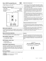
Loop Powered Beacon
A loop powered flashing beacon is available for applications where
visual alarm indication is required such as areas of high ambient
noise or buildings which are used by people who are hard of
hearing.
Dedicated Stand Alone Sounders
Stand alone sounders are ideal for applications where greater
sound outputs are required than can be achieved with a base
sounder or for applications requiring a higher level of resilience or
ingress protection.
Two different versions are available standard version and an IP66
rated version.

12
Technical Data PR202-50-502-22
Effective June 2017
CF2000 System
EATON www.eaton.com
Interfaces
CF2000 has been designed to be suitable for a wide range of
applications, various interfaces have been developed to enable
the simple integration of other fire systems or building control and
safety systems. The following devices are available:
3 Channel I/O device (CIO351)
CIO351 has 3 input channels and 3 output channels. It is used
to monitor up to three separate inputs from equipment such as
sprinkler flow switches and also to provide 3 separately controlled
volt free output contacts which are intended to be used to control
external equipment such as air handling plant or access control
systems.
All inputs and outputs operate completely independently of each
other and can be programmed using the sophisticated cause
and effect capabilities of CF2000 to operate either globally or in
response to activation of specific devices or specific inputs.
Inputs are monitored for open and short circuits. A specific
resistance is required to activate an alarm condition, fully open or
short circuit conditions are monitored and generate a system fault
signal.
Inputs are suitable for use as fire signal inputs such as from a
sprinkler flow switch, however they can also be used to monitor
non fire inputs such as external keyswitches.
Outputs are rated to switch a maximum of 1A resistive at 30V DC.
The CIO351 is supplied in a surface mounting IP65 box.
Single Channel I/O device with mains rated switching
capability (CMIO353)
CMIO353 is a single channel input / output unit. The output is
capable of switching up to 1A at 230V AC. It is commonly used
for applications such as door release controls and plant shut down
signalling
The input is monitored for open and short circuits. A specific
resistance is required to activate an alarm condition, fully open or
short circuit conditions are monitored and generate a system fault
signal.
The input is suitable for use as a fire signal input such as from a
sprinkler flow switch. However it can also be used to monitor non
fire inputs such as an external keyswitch.
The CIO353 is supplied in a surface mounting IP65 box.

13
Technical Data PR202-50-502-22
Effective June 2017
CF2000 System
EATON www.eaton.com
Zone Monitor units
CZMU352
CZMU352 is designed to enable a zone of compatible conven-
tional detectors and callpoints to be connected into the CF2000
loop, it is compatible with up to 20 Menvier conventional detec-
tors connected via CAB300 bases.
Please refer to local standards e.g.BS5839 Pt1:2002 for details
of the maximum allowable area to be covered by a single spur /
zone. CZMU352 fixes to a standard, deep, double gang back box
and can be either surface or semi recess mounted. When semi
recessed only the front section protrudes giving a maximum
29mm depth.
CZMU352-IS
Similar to the above but the detection zone has been programmed
to accept a Zener barrier and a zone of intrinsically safe detectors.
End of line for this zone now becomes 6K8 and the diode in the
detector base must be removed.
Shop Unit Interface
MSU840 accepts a zone of conventional detectors plus an unlim-
ited number of callpoints which can be connected to the same
input as the detectors or a separate callpoint input if required. It
also has a 24V 1A rated relay output, and a facility to connect a
power supply, which can then be monitored for fault.
In addition it has the facility to connect two circuits of conven-
tional polarised sounders, which are monitored by means of an
end of line resistor and powered in alarm conditions from the
external power supply.
The sounder circuits can be programmed to operate in pulsed,
continuous or time delayed mode.
Please refer to local standards e.g. BS5839 Pt1:2002 for details of
the maximum allowable area to be covered by a single spur / zone.

14
Technical Data PR202-50-502-22
Effective June 2017
CF2000 System
EATON www.eaton.com
Spur Isolator
CSI350 Enables soft addressing to work when the loop contains
spurs, it controls the addressing operation so that when the
system reaches a spur, all devices on the spur are allocated
an address before it continues addressing the loop. CSI350 is
mounted on a standard deep double gang back box (supplied).
The device also incorporates a short circuit isolator. Because each
device contains a short circuit isolator only 1 is required at the
start of each spur.
Please refer to BS5839 Pt1:2002 for details of the maximum
allowable area to be covered by a single spur / zone.
4 Way Sounder Circuit Controller
CSC354CPR provides power for 4 separately controllable conven-
tional sounder circuits, each circuit can be separately programmed.
It has been designed to greatly simplify installation in applications
where specialist sounders or beacons are required since it powers
the sounders and allows full control of the sounder operation
without having to wire the sounder back to the CF2000 control
panel. A 4 way unit takes up a single address but each circuit can
be independently controlled.
An CSC354CPR unit requires a local un-switched 230V supply and
incorporates a back up battery to 24 hours of standby operation
followed by a minimum of 30 minutes of full alarm ringing.
A standby of 72 hours can be achieved at the expense of reduced
load capability.

15
Technical Data PR202-50-502-22
Effective June 2017
CF2000 System
EATON www.eaton.com
Micro Interfaces
A range of micro interfaces modules are also available:
MIU872 is a compact single zone input, soft addressed, micro-
interface, incorporating integral short circuit isolators. It is fully
compatible with the current range of Cooper analogue fire detec-
tion panels. It is suitable for interfacing a zone of up to 20 conven-
tional Cooper detectors onto a Cooper analogue fire panel. It will
operate with any Cooper conventional detector in configuration
with a schottky diode type base.
MCIM is a compact input module used to accept input signals
from external equipment such as beam detectors, flow switches,
valve monitor switches etc. The CF6000 can be programmed to
perform different actions based on the state of the input. The
maximum number of input devices per loop is 200.

16
Technical Data PR202-50-502-22
Effective June 2017
CF2000 System
EATON www.eaton.com
Equipment Compatibility
Sensors
Loop wired sensors must be of the Cooper Fire Systems 300
series soft addressed analogue type. Cooper Fire Systems 300
series conventional detectors can be connected via an CZMU352
interface. The connection of other detector types via an
CZMU352 interface is not recommended,
Call points
Loop wired call points must be the Cooper Fire Systems 300
series soft addressed analogue type, Cooper Fire Systems 300
series conventional callpoints can be connected via an CZMU352
interface. The connection of other callpoint types via an CZMU352
interface is not recommended,
Sounders
Loop powered addressable sounders must be of the Cooper Fire
Systems 300 series soft addressed analogue type.
Conventional sounders can also be connected either to the
conventional sounder circuits at the panel or to the loop via a
CSC354 addressable sounder controller interface providing they
meet the following:
1. They are suitable for operation between 18V and 28V.
2. They are polarised and suppressed.
3. The total alarm load is less than the rating of the panel /
Alarm Power Interface.
Note: It is possible to use devices outside these requirements
if they are supplied with power from a separate source and
switched via a suitable relay.
Relay circuits
Additional relays can be added to the CF2000 system by using
either CMIO353 or CIO351 relay units.
Relays / Auto-dialers and auxiliary equipment
A wide variety of relays and other equipment can be connected to
the CF2000 system, but you should note the following constraints:
1. CF2000 provides monitored outputs to drive fire and fault
relays mounted in external equipment. External relays should
be suppressed. If a non-suppressed relay is used then a
diode can be connected , to suppress any reverse EMF
on the release of the relay which might cause the panel to
malfunction.
2. A 24V DC output is provided at the panel to make it easy to
connect ancillary equipment. Although the panel can supply a
continuous quiescent load of up to 30mA, BS5839 precludes
this practice and any ancillary equipment you connect should
only consume power in the alarm or fault mode to meet the
requirements of BS5839.

17
Technical Data PR202-50-502-22
Effective June 2017
CF2000 System
EATON www.eaton.com
System Overview
Simple user interface
The main element of the user interface with CF2000 is a (60mm
x 30mm visible area) display, which provides comprehensive user
information.
As well as an LCD display providing full system status informa-
tion, the panel incorporates 32 traditional zone indication LEDs
to provide clear information about the status and spread of a fire
even to a user who is completely unfamiliar with the operation of
the system.
In addition there are a number of system status LEDs designed to
give clear status information to non technical users
User configuration and maintenance facilities
CF2000 has comprehensive facilities for on site system configura-
tion, whereby the user can add or remove simple devices, without
the need for a service engineer to visit site.
For initial configuration or major system changes special PC
configuration software is available enabling Eaton personnel to
do this more efficiently than can be achieved using the system
screen. Exiting configurations can be uploaded to the PC so that
changes can be made to the existing system rather than having to
revert to initial files.
During the yearly maintenance, all terminal under main supply
shall be verified.
Spur tolerant soft addressing
CF2000 utilises intelligent soft addressing technology to greatly
simplify the installation and commissioning processes.
Once the system has been installed and the autolearn menu
selected, the CF2000 control panel will automatically scan the
detection loops and allocate each device with an address number
corresponding with its position on the loop. This avoids the tradi-
tional need for manual addressing of the system devices which is
time consuming and provides a potential for error.
A major innovation with CF2000 is the ability to incorporate spurs
of analogue devices which are fed from the main loop by utilising
a spur isolator.
Whenever the panel detects a spur, it breaks from allocating
address numbers to the loop wired devices, allocates address
numbers to each of the devices on the spur in sequence and then
continues to address the devices on the main loop.
Every CF2000 analogue device incorporates an integral short
circuit isolator ensuring maximum system integrity. A single short
circuit will not disable any loop-mounted devices. The isolators
in the devices each side of the short circuit will operate and the
CF2000 control panel will drive communication from both ends of
the loop.
The spur isolator also incorporates a short circuit isolator such that
in the event of a short circuit on the spur, the integrity of the main
loop will not be compromised.
Please refer to local standards for details of the maximum allow-
able area to be covered by a single spur.
Integral Power Supply and Battery
The CF2000 panel is designed for ease of installation, the power
supply and battery are integral to the main control panel so only a
single panel is required.

18
Technical Data PR202-50-502-22
Effective June 2017
CF2000 System
EATON www.eaton.com
Technical Specification
Power Supply (Approved EN54 pt 4)
Mains
Nominal Voltage 230V AC + 10%, -15%
Nominal Current 40mA
Maximum Current 500mA
Input Fuse R1
Anti Surge 1.6A
Output Voltage including
tolerances
26V = 18.5 to 29.5V
26V RAW = 18.5 to 29.5V
5V Output = 4.6V to 5.5V
Ripple Voltages 26V = 800mV
26V RAW = 800mV
5V Output = 430mV
Maximum Loadings 26V O/P = 0.48A
26V RAW O/P = 1.2A
5V = 0.5A
Standby Current
(2 Loops Loaded)
26V = 140mA
26V RAW = 50mA
26V = 140mA
26V RAW = 50mA
5V = 30mA
* I max a, I max b & I min = Current as specified in BS EN54-4 Published 2006 (Amendments 1 & 2)
Batteries
Number of Batteries 2
Manufacturer YUASA NP7-12
Capacity 7Ah
Battery Fuse
6.3A Anti-Surge (F4)
Maximum battery current 3.0A
Standby current (mA) 125 (2 loops)
Maximum Charging Current
to the Batteries
0.65A
Float Voltage 27.4V
Final Voltage 21.0V
Charging Characteristics Constant Voltage with 0.65A limit with temperature compensation
Maximum current drawn
from the batteries when the
mains is not available
3.0A
Deep Discharge Protection 20.6V
Battery Internal Impedance
Fault
>0.5Ω
Inputs
Addressable Loops
Max Number 2
Max Loop Load per loop 200mA
Max Number of
Addressable Devices per
loop
200
Class Change Operated by external volt free contact
WARNING
RISK OF EXPLOSION IF BATTERY IS REPLACED BY AN INCORRECT TYPE. DISPOSE OF USED BATTERIES ACCORDING TO THE
INSTRUCTIONS GIVEN IN APPENDIX 14 BATTERY DISPOSAL INSTRUCTIONS.
}
*I max b
}
*I max a
}
*I min

19
Technical Data PR202-50-502-22
Effective June 2017
CF2000 System
EATON www.eaton.com
Technical Specification (continued)
Outputs
Conventional sounder circuits
Number of sounder circuits 4
Total Sounder Load
1.0A (FH1204)
Maximum Sounder Circuit Load 800mA
Sounder Circuit Fuses (F1/2/3/4) 1.6A (Quick Blow)
End of line resistor 6k8
Fire Routing Equipment
Max Load 60mA
Fused (PTC2) 100mA polyswitch
End of Line resistor 6k8
Fire Protecting Equipment
Max Load 60mA
Fused (PTC4) 100mA polyswitch
End of Line resistor 6k8
Fault Routing equipment
Max Load 30mA
Fused (PTC1) 100mA polyswitch
End of Line resistor 6k8
Auxiliary Relays
The auxiliary relays provide fused volt free change over contacts. These contacts are not monitored.
Max Load 24V 1A
Fuse (PTC5)
1.1A polyswitch
Auxiliary 24V Supply
Nominal Voltage 24V ±10%
Fuse (PTC3) 300 mA polyswitch
Maximum current 30 mA
This output is not to be used for Fire protecting equipment or Fire alarm routing Equipment
Any power taken from the alarm system will affect the standby duration
RS485 Port (Mimic Repeater)
This is a serial output port for driving CF2000 Repeater panels, mimics etc.
This output is short circuit protected
Max Cable Length 2 Km
Min Recommended cable size 1 mm² (Screened)
Mechanical Specification
Weight including batteries
10.6 Kg
Weight excluding batteries 5.3 Kg
Dimensions (Standard batteries) 400 mm (L) x 320 mm (H) x 170 mm (D)
Type of Material (backbox) Mild Steel (Powder Coated)
Type of Material (facia) PC/ABS
Flammability Rating UL 94 V0
Total Number of knockouts 24
Diameter of knockout 20 mm
CAUTION
TERMINAL BLOCKS: DO NOT USE EXCESSIVE FORCE WHEN
TIGHTENING THE SCREWS ON THE TERMINAL BLOCK

20
Technical Data PR202-50-502-22
Effective June 2017
CF2000 System
EATON www.eaton.com
Optional Functions as per EN54 Parts 2 & 4
CF2000 is approved to EN54 Parts 2 & 4 including all the options
in this section which can be selected as required. Figure 3 on
page 23 is a typical system wiring diagram, which shows the
recommended connections for the equipment described in this
section.
Panel Inputs
Class Change: (Option not required by EN54)
A pair of terminals are provided for class change. By shorting
these terminals together (e.g. Switch, Time clock) the alarm will
sound (panel sounders + loop sounders only). The Panel will not
indicate a Fire. The alarm will cancel when the short circuit is
removed.
CAUTION
EQUIPMENT DAMAGE: NO VOLTAGE SHOULD BE APPLIED TO
THIS INPUT
Panel Outputs
Panel Sounders: (Option 7.8 EN54 Part 2)
Two pairs of outputs are provided (see Figure 1). ONLY polarised
equipment should be used.
Ensure the polarity of the connections are observed at all times
and end of line resistors (6K8 5%) are fitted for correct operation.
The total alarm load across all sounder outputs = 1.0A
All outputs are fused with 1.6A Glass fuse. Alarm devices should
be spread equally across the four sounder circuits.
Figure 1. Typical Sounder circuit
WARNING
DO NOT EXCEED THE RATED OUTPUT CURRENT
Output to Fire Alarm Routing Equipment
(Option 7.9 EN54 Part 2)
This output, which is fused, and monitored using a 6K8 end of line
resistor, is used for the automatic transmission of the fire signals
to Fire alarm routing equipment (e.g. Fire Brigade). It operates by
providing a 24V DC output to an auxiliary device (e.g. relay).
It is current limited to 30mA using a resettable polyswitch. Class
change and test conditions do not operate this output. If operated
under a fire alarm condition, the FRE LED will illuminate and will
remain illuminated until the fire alarm is reset.
Ensure the polarity of the connections are observed at all times
and end of line resistors (6K8 5%) are fitted to ensure correct
operation.
Output to Fire Alarm Protecting Equipment
(Option 7.10 EN54 Part 2 Option A)
This output, which is fused, and monitored using a 6K8 end of line
resistor, is used for the transmission of the fire signals to controls
for automatic fire protecting equipment (e.g. Door released units
etc). It operates by providing a 24V DC output to an auxiliary
device (e.g. relay).
It is current limited to 30mA using a resettable polyswitch. Class
change and test conditions do not operate this output. If operated
under a fire alarm condition, this output remains energised until
the fire alarm is reset.
Ensure the polarity of the connections is observed at all times
and end of line resistors (6K8 5%) are fitted to ensure correct
operation.
Output to Fault Warning Routing Equipment
(Option 8.9 EN54 Part 2)
This output, which is fused and monitored using a 6K8 end of
line resistor, is used for the transmission of fault signals to fault
warning routing equipment. This output is monitored using a 6K8
end of line resistor and is current limited to 30mA. Under normal
condition it operates by providing 12V DC which can be connected
directly to a 12V auxiliary device (it is current limited to 30mA).
Under fault conditions or even if the CF2000 is powered down,
this output will be switched to 0V.
Ensure the polarity of the connections is observed at all times
and end of line resistors (6K8 5%) are fitted to ensure correct
operation.
Delays to outputs (Option 7.11 EN54 Part 2)
The CF2000 has the option to delay the operation of panel sound-
ers, the Fire Routing equipment output and the Fire Protecting
equipment. This delay is selectable using the CF2000 Site Installer
download software. The delay is configurable in increments of 1
minute up to a maximum of 10 minutes.
This delay can be enabled and disabled at access level 2.
The CF2000 has the facility for a specific call point to override
this delay by programming this call point via an input interface
to provide an evacuate signal using the CF2000 Site Installer
software.
Dependencies on more than one alarm signal - Type C
(Option 7.12.3 of EN54 Part 2)
The CF2000 has the facility to inhibit the operation of the output
sounders, output to fire alarm routing equipment and the output
of the fire alarm protecting equipment until one more confirmatory
signals are received from different zones. This feature is program-
mable using the CF2000 Site Installer software.
Optional Functions as per EN54 Parts 2&4
1. Auxiliary Relay (Option not required by EN54)
This output is a volt free contact, which is protected by a poly-
switch. It is rated at 24V DC 1A. If operated under a fire alarm
condition, this output will remain energised until the fire panel is
reset.
DO NOT USE TO SWITCH MAINS VOLTAGE
2. Auxiliary DC Output (Option not defined by EN54)
A 24V DC output is provided. This output is protected by a poly-
switch. This output can be used to power fire or fault auxiliary
equipment. Please ensure that all equipment connected to this
output will only draw current when a fire condition exists.
WARNING
DO NOT EXCEED THE RATED OUTPUT CURRENT
3. Mimic Output (Option not required by EN54)
This RS485 output is used to send data to a mimic display or a
repeater panel. The maximum distance is 2 km.
/