Nexus UltraMatic UMW Installation Operation & Maintenance

Type
Installation Operation & Maintenance
INSTALLATION
-OPERATION-MAINTENANCE
Effective Date:
February 13, 2019
P
lease read and follow instructions within. Disregarding these instructions may
result
in poor performance and / or product failure and void your warranty.
Nexus Valve, Inc.
Tel
888.900.0947
Fax
800.900.8654
9982 E. 121st Street
Fishers, IN 46037
www.nexusvalve.com
info@nexusvalve.com
Table of Contents
Limite
d Warranty……………………………………………………………………………………………………………………………………..1
General Information .......................................................................................................................................... 2
UltraMatic .................................................................................................................................................... 11
Dynamic™ ....................................................................................................................................................... 18
UltraXB™ Orturi .............................................................................................................................................. 23
UltraMB™ ........................................................................................................................................................ 26
Nextrol™ ......................................................................................................................................................... 33
UltraMBF™...................................................................................................................................................... 38
Nexus Venturi Model NV ............................................................................................................................ 44
Strainex™ ........................................................................................................................................................ 47
UltraY ........................................................................................................................................................... 49
UltraX ........................................................................................................................................................... 52
UltraNXP™ ...................................................................................................................................................... 53
UltraU™ .......................................................................................................................................................... 54
Valves for Actuators (UMA / MBA) ................................................................................................................... 55
Ultra BK™ Bypass Kits .................................................................................................................................... 59
UltraT ........................................................................................................................................................... 61
Standard Ball Valve ......................................................................................................................................... 62
NXU / NXS / NXH ............................................................................................................................................. 63
UltraFlex™ ...................................................................................................................................................... 64
Meter Kits MKA............................................................................................................................................. 69
Meter Kits MKM ............................................................................................................................................ 70
Manual Air Vents ............................................................................................................................................. 71
Handle Extension Kits ..................................................................................................................................... 72
Extension PTE / PTEB...................................................................................................................................... 73
Union Adapter ................................................................................................................................................. 74
Tool Requirements .......................................................................................................................................... 75
Replacement O-Rings ..................................................................................................................................... 76
Replacement Gaskets ............................................................................................
......................................... 77
Notes ............................................................................................................................................................... 78
Installation - Operation - Maintenance
Nexus Valve, Inc.
9982 E. 121
st
Street
Fishers, IN 46037
(888) 900-0947 (800) 900-8654 Fax
info@nexusvalve.com www.nexusvalve.com
Effective Date:
February 13, 2019
LIMITED WARRANTY
1
All goods sold hereunder are warranted to be free from defects in material and factory workmanship for the
applicable Warranty Period. Various other products supplied through Nexus from an other manufacturer, such as
temperature control valves, shall be subject to that manufacturers’ warranty. Any misapplication, tampering,
adjusting, abuse or other changes in the field to Nexus products will result in the automatic voiding of the Nexus
limited warranty.
Repla
cement Parts
Nexus will replace or repair any of its valves, unions, or accessories which is determined to be defective in
workmanship or material, free of charge, provided such products are installed in accordance with the best practices
accepted in the trade and recommended in the Nexus Valve I.O.M.
Liabil
ity
THE LIABILITY OF NEXUS IS LIMITED TO REPLACEMENT OR REPAIR OF THE DEFECTIVE PART WHICH MUST BE
RETURNED TO NEXUS WITH WRITTEN NOTICE BEFORE SUCH REPLACEMENT OR REPAIR IS MADE. NEXUS IS NOT
LIABLE FOR INCIDENTAL OR CONSEQUENTIAL DAMAGES, INCLUDING BUT NOT LIMITED TO LOSS OF PROFIT,
EXPENSES OF DELAYS, AND LOST SERVICE TIME.
Exclusi
ons
This warranty applies only to defects in workmanship or material. The warranty does not include threaded
connections, union connections, press or push connections, O-rings, gaskets, field connections, or products subject to
conditions beyond those specified for the products. This warranty is in lieu of all other warranties, whether expressed
or implied.
WARRANTY PERIOD
PRODUCT GROUP
WARRANTY PERIOD
Nexus Valve
5 Years from Date of Purchase
Efficiency & Safety
5 Years from Date of Purchase
Pressurization & Storage
5 Years from Date of Purchase
Vacuum Deaeration
2 Years from Date of Purchase
Various
Subject to OEM Warranty. Contact Nexus for details.
Installation - Operation - Maintenance
Nexus Valve, Inc.
9982 E. 121
st
Street
Fishers, IN 46037
(888) 900-0947 (800) 900-8654 Fax
info@nexusvalve.com www.nexusvalve.com
Effective Date:
February 13, 2019
GENERAL INFORMATION
2
General Information
Symbology
Important Information Please Review Reference To Alternate Page
Unacceptable Installation
Do Not Violate This Information
Acceptable Installation
Threaded Connections
Threaded connections in the field should be made according to specified or industry-accepted standards. All
tapered pipe thread connections of Nexus Valve products conform to the ANSI/ASME B1.20.1-1983 American
National Standard for Taper Pipe Threads (NPT threads).
When installing valve bodies with a threaded connection, it is imperative to use the flats provided on the
threaded connection to resist the torque required for tightening the mating pipe threads.
DO NOT PLACE WRENCH / TOOL ON VALVE BODY!
The threads provided on Nexus Valve union connections are straight threads with no taper, conform to the
ANSI/ASME B1.20.7-1991 American National Standard for Hose Coupling Threads (NPSH threads), and
require an o-ring or gasket per design to seal.
Piping connections to a union tail piece must only be made while the tail piece is disconnected from the union.
The union connection can be reassembled after the tail piece piping connection is completed.
Factory installed accessories (PT test plugs, MV air vents, PG plugs, BD drain valves, etc). are sealed at the
factory and should not be disturbed after delivery.
Sweat Connections
Nexus Valve products with sweat connections are intended for “soft” solders with low melting temperatures.
They are not designed for "silver" solders or other high temperature soldering methods. Use a standard
approved soldering procedure including proper preparation of the copper pipe and cleaning of the pipe, valve
connection, and/or union tail piece fitting.
AVOID OVERHEATING THE VALVE OR OTHER COMPONENTS WHEN MAKING SWEAT CONNECTIONS!
A HEAT SINK - SUCH AS A WET RAG - MUST BE USED WHEN MAKING SWEAT CONNECTIONS!
Installation - Operation - Maintenance
Nexus Valve, Inc.
9982 E. 121
st
Street
Fishers, IN 46037
(888) 900-0947 (800) 900-8654 Fax
info@nexusvalve.com www.nexusvalve.com
Effective Date:
February 13, 2019
GENERAL INFORMATION
3
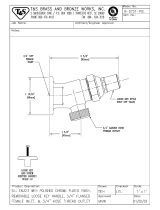
For valve bodies with integral sweat fittings, special care must be taken to avoid overheating the seals, o-
rings, and sealant used in the valve body assembly. Position the valve lever or handle in the open position to
eliminate pressure buildup and dissipate heat and use a heat sinking method.
FAILURE TO PROTECT THE VALVE BODY AND SEALS CONTAINED WITHIN THE VALVE BODY FROM
OVERHEATING WILL CAUSE THE SEALS TO FAIL, THE VALVE TO LEAK, AND WILL VOID THE NEXUS
VALVE WARRANTY.
For valve and/or union bodies with a sweat type union end tail piece, the tail piece must be removed from the
valve or union body before heat is applied to avoid damaging the union o-ring.
NexPress™ Connections
The NexPressconnection is for use with Types K, L, and M hard copper tubing. The maximum working
pressure on the NexPressfitting is 200 psi and is manufactured for water and water/glycol systems. For
the connection to work “leak free” it is mandatory that the end of the copper tube be properly “dressed.”
Failure to “dress” the tube properly will result in a torn or damaged o-ring and result in a weak or leaking
seal. To properly use NexPressfittings:
We recommend not using pipe fittings that do not have the required length of straight pipe. If using
pipe fittings, be sure to properly dress them.
Cut the end of the tube square.
Remove all dirt, debris & burrs inside and outside.
Chamfer the leading edge of the tube 5mm by 30 degrees.
Ensure that the o-ring is present in the fitting, check that the o-ring is positioned evenly in the fitting’s
groove and is free of dirt, oil or other foreign materials.
Insert tubing into the fitting, ensure that the tubing inserts fully into the fitting.
If the tubing is difficult to insert, a little water or a food grade silicone spray may be applied to the
tubing.
Once the tubing is fully inserted, the fitting must be crimped using crimping tools, Ridgid ProPress,
Stanley, NIBCO, etc.
A minimum distance between press fittings must be ½ the tubing diameter.
Consider clearance requirements between wall/ceiling & piping for the press tool.
When transistioning to threaded connections, the threaded connection is made first.
A minimum distance, when pressing a connection near an existing brazed fitting, of 2x the tubing
diameters is required.
A minimum distance, when pressing a connection near an existing solder fitting, of ½ the tubing
diameters is required.
When soldering near a NexPress™ connection a minimum distance of 3x tube diameters is required.
When brazing near a NexPress™ connection a minimum distance of 9x tube diameters is required.
A minimum distance of 4” must be maintained when welding a pipe adjacent to a pipe with a
NexPress™ connection.
Installation - Operation - Maintenance
Nexus Valve, Inc.
9982 E. 121
st
Street
Fishers, IN 46037
(888) 900-0947 (800) 900-8654 Fax
info@nexusvalve.com www.nexusvalve.com
Effective Date:
February 13, 2019
GENERAL INFORMATION
4
A minimum distance of 3’ must be maintained when welding on the same pipe as a NexPress™
connection.
A minimum distance of 4” must be maintained when attaching a sliding pipe hanger to a pipe with a
NexPress™ connection.
Pressure surges that result in water hammer effects can cause damage to the press fittings.
Pressing causes pipe deflection. To minimize this, alternate the position of the press tool on each
fitting connection in a piping line.
After crimping, inspect and mark that the fitting has been crimped. Check for leaks.
Tube Size
(Inch)
Required Insertion
Depth (Inches)
½”
13/16
¾”
1”
1”
1”
1¼”
1”
1½”
1
7
16
2”
1
5
8
Nex
Lok™ Connections
NexLok™ and NexLok™ LD connections are for use with ASTM B88 hard drawn and annealed Type K,L, and M
copper tubing ½” through 2” and with ½” through 2” PEX tubing with a Nexus Tube Liner. The NexLok™
fitting is designed for 1/2 “ to 1“ tubing and is rated for temperatures of 0⁰F to 200⁰F with a maximum
working pressure of 250 PSI. The NexLok™ LD is designed for 1-1/4” through 2” tubing and is rated for
temperatures of 0⁰F to 200⁰F with a maximum working pressure of 200 PSI. Both the NexLok™ and The
NexLok™ LD are manufactured for water and water/glycol systems.
For the connection to work properly it is mandatory that the following instructions be followed:
We recommend not using pipe fittings that do not have the required length of straight pipe. If using
pipe fittings, be sure to properly dress them.
The NexLok™ fittings must not come in contact with household or industrial cleaning products, paints,
greases, fluxes, mineral oils, adhesives, nitrates or other solvents during installation or after
installation.
The exterior surface of the NexLok™ fitting should not be painted.
All proprietary flushing chemical should be reviewed with Nexus engineering prior to use.
Soldering or brazing should not be done within 12” of the NexLok™ fitting.
All soldered or brazed piping systems must be cool to touch before insertion into the NexLok™ fitting.
When transitioning to threaded connections, the threaded connection should be made first.
Installation - Operation - Maintenance
Nexus Valve, Inc.
9982 E. 121
st
Street
Fishers, IN 46037
(888) 900-0947 (800) 900-8654 Fax
info@nexusvalve.com www.nexusvalve.com
Effective Date:
February 13, 2019
GENERAL INFORMATION
5
All TCV’s should be atleast 5 tubing diameters from each NexLok™ fitting.
Inst
allation of ½” through 2” tube:
Cut the tube square (perpendicular to centerline of tube) with a tube cutter
Remove burrs by chamfering the inside and outside diameters of the tube
Mark the required insertion depth of the tube (See table below following page).
Tube Size
(Inch)
Required Insertion
Depth (Inches)
½”
15
16
¾”
1⅛”
1”
1
5
16
1¼”
2¼”
1½”
2⁷⁄₁₆”
2”
2¾”
A Ne
xus Tube liner / PEX insertion sleeve must be inserted into the PEX tubing before inserting into
the NexLok™ connection.
Holding the fitting firmly, insert the tube straight into the fitting with a twisting motion until the depth
mark on the tube is aligned with the end of the fitting.
Check that the depth mark is at the end of the fitting, if not, continue to push the tube to the full
insertion depth.
A minimum distance between press connections, after full insertion depth, should be 1”.
Once the tube is correctly installed to the proper depth, limit rotation of the tube.
Inserting a properly prepared tube straight into the NexLok™ fitting will produce a leak free joint,
will reduce insertion force, will prevent o-ring damage, and will insure the tube may easily be
inserted to the proper depth. Failure to properly prepare the tube, inserting at angle and pulling
the tube into proper alignment with the fitting is poor assembly practice and may result is a
leaking joint.
DO NOT insert anything into the NexLok™ grab ring fitting other than water tubing; it may not
release. This warning includes human body parts and is critical to your health and safety. Seek
emergency medical services if you become entangled in the grab ring mechanism inside the
NexLok™ fitting.
Installation - Operation - Maintenance
Nexus Valve, Inc.
9982 E. 121
st
Street
Fishers, IN 46037
(888) 900-0947 (800) 900-8654 Fax
info@nexusvalve.com www.nexusvalve.com
Effective Date:
February 13, 2019
GENERAL INFORMATION
6
Removal of the tube from the NexLok™ fitting:
Select the correct size removal tool for the job;
Place the removal tool around the tube next to the fitting assembly. The flat side of the tool should be
placed in contact with the fitting.
Push the removal tool toward the fitting firmly until the grab ring is compressed.
With the removal tool firmly held in place, use a twisting, and pulling motion to remove the tube from
the fitting.
Release the removal tool after the tube is removed.
If the tube is to be re-used, check the tube for score marks, and any other defects such as dirt, or
chips.
If any defects exist, the tube must be repaired as needed to meet the installation requirements
detailed previously in this installation manual.
Check the internal parts of the fitting. The grab ring, pipe guide, and o-ring must be in the housing and
aligned with the fitting opening.
If all of the parts are in good condition, and aligned, then the fitting is ready to be assembled with a
properly prepared pipe or tube.
Remo
val of the tube from the NexLok™ LD fitting:
Ensure water pressure is removed from piping and the piping section isolated.
Using a the adjustable spanner wrench from Nexus, place the wrench tangs in the opposing slots in
the end cap and loose the end cap by turning wrench counter clock-wise (Fig 1).
Pull the end cap away from the fitting.
Remove the pipe and the grip ring from the fitting.
Use an acceptable tool and cut the grip ring from the pipe. Care should be taken with the grip ring to
avoid injury.
Ensure the o-ring and protection ring are seated into the fitting if not well seated ensure
reassembly in the same sequence as removed from the fitting.
Place a NEW grip ring, available from NEXUS into the fitting. Ensure seating againse the protection
ring. Ensure the grip ring seats with the taper facing inward toward the o-ring.
Re-inert end cap and tighten into the fitting until snug the fitting is ready for tube inserting. Be sure
to follow instruction above for preparing the tube for insertion.
Figure 1 Figure 2
Installation - Operation - Maintenance
Nexus Valve, Inc.
9982 E. 121
st
Street
Fishers, IN 46037
(888) 900-0947 (800) 900-8654 Fax
info@nexusvalve.com www.nexusvalve.com
Effective Date:
February 13, 2019
GENERAL INFORMATION
7
Rem
oval of tube from the NexLok™ using demount rings
Using a the adjustable spanner wrench from Nexus, place the wrench tangs in the opposing slots in
the end cap and loose the end cap by turning wrench counter clock-wise (Fig 1).
Slide the cap away from the fixed end on the pipe.
Take the appropriate sized demount ring provided by Nexus, and snap it over the pipe between the cap
and grip ring (Fig 2).
Ensure the tapered end of the demount ring is facing the grip ring.
Guide the cap back onto the fixed end and hand tighten.
Twist and pull the pipe from the fixed end.
Unscrew the cap and remove the demount ring.
Union Tail Piece Installation
Nexus Valve manufactures a series of interchangeable union end tail pieces for 1/2” through 2-1/2”
connections.
Preparing for Installation of Union Tail Pieces
For both threaded and sweat types of tail pieces, the union tail piece must be disassembled from the valve or
union body for the installation procedure. Separate the union tail piece from the valve body by removing the
union nut, taking care not to lose or damage the union o-ring. Care must also be taken not to damage the
o-ring sealing surface of the tail piece during handling and the installation procedure. This surface must not
be scratched, deformed, or otherwise damaged in any way if the union o-ring seal is to perform properly.
Installation of Threaded Union Tail Pieces
Refer to instructions on Preparing for Installation of Union Tail Pieces before proceeding.
Position the union nut on the pipe side of the tail piece connection prior to installing the tail piece on the pipe,
so that the union nut is available to reassemble the union connection.
Threaded tail pieces should be held properly during the thread tightening process. It is critical that the
internal hex keyway or external tool flats provided on the tail piece be used to resist the torque required for
tightening.
Nexus Valve threaded tail pieces for 1/2" through 1" NPT connections have an internal (female) hex keyway to
facilitate installation. For these tail pieces, the proper hex key size for each NPT connection size is given on
page 75. Nexus Valve offers a tool kit that includes the appropriate hex keys.
For valves equipped with 1-1/4" through 2" NPT threaded tail pieces, use the provided flats around the
circumference of the fitting to hold and tighten the tail piece.
Installation - Operation - Maintenance
Nexus Valve, Inc.
9982 E. 121
st
Street
Fishers, IN 46037
(888) 900-0947 (800) 900-8654 Fax
info@nexusvalve.com www.nexusvalve.com
Effective Date:
February 13, 2019
GENERAL INFORMATION
8
If necessary, apply pipe sealant to pipe threads per industry standard practice. Note that Nexus Valve
supplies some male thread components with pre-applied Loctite® sealant; while found to be an effective
timesaver, this provision is a convenience feature only and the performance of this sealant is not warranted.
Tighten the tail piece per industry standard practice and proceed to Completing the Installation of Union End
Tail Pieces.
Installation of Sweat Union Tail Pieces
Refer to instructions on Preparing for Installation of Union Tail Pieces before proceeding. Union tail pieces
with a sweat type connection must be disassembled from the valve or union body before making the soldered
connection. Separating the union tail piece from the valve or union body allows the soldering procedure to be
done without overheating and damaging the o-ring seal of the union connection.
Position the union nut on the pipe side of the tail piece connection prior to installing the tail piece on the pipe,
so that the union nut is available to reassemble the union connection.
Perform the soldering procedure in accordance with industry standard practice while adhering to the
guidelines in Section II, Sweat Connections on page 2.
Allow the soldered connection to cool to ambient temperature before proceeding! Attempting
to reassemble the union connection before allowing the soldered piece to cool will damage the
union o-ring.
Proce
ed to Completing the Installation of Union End Tail Pieces.
Completing the Installation of Union Tail Pieces
After following the proper installation procedures for installation of the union end tail piece and the
associated valve or union body, the union connection with o-ring may be reassembled. Follow the installation
and assembly instructions on page 8 named, Union O-Ring Installation & Union Assembly.
Union O-Ring Installation & Union Assembly
An o-ring seal is a dynamic seal in that it is intended to move within the o-ring groove or gland. The o-ring
groove is purposely designed wider than the o-ring width - per design standards for o-ring sealing
applications so that the o-ring may move to seal the leak path when pressure is applied.
PIPE DOPE OR SEALANT SHOULD NEVER BE APPLIED TO THE O-RING, O-RING GROOVE, OR
MATING SURFACE.
Inspect the o-ring groove for damage or debris (including pipe sealant). Inspect the mating surface of the tail
piece flange to insure that it is not scratched, deformed or otherwise damaged. Any damaged components
must be replaced.
Installation - Operation - Maintenance
Nexus Valve, Inc.
9982 E. 121
st
Street
Fishers, IN 46037
(888) 900-0947 (800) 900-8654 Fax
info@nexusvalve.com www.nexusvalve.com
Effective Date:
February 13, 2019
GENERAL INFORMATION
9
Carefully place the o-ring in the groove. Use of a quality non-petroleum based o-ring lubricant at the time of
installation will help protect the O-ring from damage by abrasion, pinching, rolling or cutting and facilitate
installation. Confirm that the o-ring is properly placed in the groove and reassemble the union connection.
Secure the union nut hand-tight, and then tighten no more then an additional ¼ turn.
Fla
nged Product Bolting Specifications
Field supplied studs, nuts and bolts should meet the following specifications:
Carbon Steel
ASME A307 Grade B material requirements
ASME B18.2.1 Square Head Bolt or Heavy
Hex Head Bolt requirements
ASME B18.2.2 Heavy Hex Nut
requirements
Recommended torque for
tightening nut and bolt.
Bolt Size
Torque ft-lb
5/8"
84
3/4"
105
7/8"
160
1st Round - 30% of final torque
2nd Round - 60% of final torque
3rd Round - 100% of final torque
One final time clockwise around flange
4 Bolt Star Pattern
Tightening Sequence
8 Bolt Star Pattern
Tightening Sequence
12 Bolt Star Pattern
Tightening Sequence
NPT Accessory Installation Procedure
Most products come assembled to factory specifications. Accessories on valves larger than 2-1/2” do not
come assembled. Nexus Valve recommends tightening accessories to the following torque specifications:
Accessories used in the 1/4” NPT to 13 - 15ft-lb.
Installation - Operation - Maintenance
Nexus Valve, Inc.
9982 E. 121
st
Street
Fishers, IN 46037
(888) 900-0947 (800) 900-8654 Fax
info@nexusvalve.com www.nexusvalve.com
Effective Date:
February 13, 2019
GENERAL INFORMATION
10
Accessories used in the 1/2” NPT to 20 - 25 ft-lb.
Accessories used in the 3/4” NPT to 23 - 30 ft-lb.
Thread sealant is pre-applied on most Nexus Valve supplied accessory MNPT connections.
Val
ve Identification
UM and UMS valves are shipped with a standard body
identification tag located on the top of the handle or body. This
tag includes the following information: flow rate (GPM), valve
size, direction of flow, and location information (if provided). An
optional hanging tag is also available.
Wafer style UltraMatic™ valves are shipped with a standard
body identification tag located on the valve body. This tag
includes the following information: model number, control
range (PSID) & flow rate (GPM).
UltraXBOrturi valves are shipped with a tag on the handle as
well as a body marking. This tag will indicate which modified
venturi tube has been installed in the valve.
Standard Hanging Tag
NextrolHanging Tag
For all valve products, an
optional hanging body tag is
available. This tag includes the
part number and upon customer
request, a tagging location.
Nextrol™ products are
shipped with a hanging tag.
This tag includes model
number, valve size, and tag
location
Installation - Operation - Maintenance
Nexus Valve, Inc.
9982 E. 121
st
Street
Fishers, IN 46037
(888) 900-0947 (800) 900-8654 Fax
info@nexusvalve.com www.nexusvalve.com
Effective Date:
February 13, 2019
ULTRAMATIC™
11
UltraMatic™
UltraMatic™ is a pressure independent automatic flow limiting valve. The UltraMatic™ is available in several
sizes and configurations.
General Information
UltraMatic™ can be installed in horizontal and vertical planes.
When installing UltraMatic™, space around the valve must be provided for port access and rotation of
the handle.
Each UltraMatichas an internal cartridge that is factory-set to a specific flow rate (GPM). This flow
rate cannot be adjusted in the field. Contact your local Nexus Valve representative if a different GPM
is required. See page 17 for instructions to replace the cartridge if this becomes necessary.
It is imperative that the valve be installed with correct direction of flow.
Installation of a y-strainer is recommended upstream for any control valve or balancing device.
To achieve maximum performance, the elimination of air in the fluid is required.
Do not back flush with the cartridge in the body. Nexus Valve recommends using an UltraBK
Series bypass and flushing kit for flushing the hydronic system prior to start up and after
periodic maintenance.
Refer to page 2 for installation procedure.
Refer to page 10 for valve identification
UltraMatic™ Model UM
The UltraMatic™ Model UM is a pressure independent automatic flow control valve (AFCV) which has both an
isolation ball valve and union integrated into one body. In various configurations, the Model UM can
accommodate several types of accessories, but comes standard with two pressure and temperature test
plugs.
Straight Run Requirements
UltraMatic™ does not typically require any straight pipe runs up or downstream. Changes in pipe diameter
size at the valve inlet may cause turbulence impacting pressure drop readings.
Accessory Port Locations
UltraMatic™ comes equipped with two (2) PT test plugs. Standard configuration will have the port # 2
designated for high-pressure and port # 1 for low-pressure. Other configurations are available, contact your
representative for assistance. (See images on next page for additional reference).
Installation - Operation - Maintenance
Nexus Valve, Inc.
9982 E. 121
st
Street
Fishers, IN 46037
(888) 900-0947 (800) 900-8654 Fax
info@nexusvalve.com www.nexusvalve.com
Effective Date:
February 13, 2019
ULTRAMATIC™
12
Standard Configuration
Alternate Configuration
Flow
Flow
UltraMatic™ Model UMS
The UltraMatic™ Model UMS is a simple SWT x SWT pressure independent automatic flow control valve
(AFCV).
Refer to page 2 for installation procedure.
Refer to page 10 for valve identification.
Straight Run Requirements
UltraMatic™ UMS does not typically require any straight pipe runs up or downstream. Changes in pipe
diameter size at the valve inlet may cause turbulence impacting pressure drop readings.
Accessory Port Locations
UltraMaticUMS does not have pressure and temperature test plugs. (See image below for reference).
Standard Configuration
Flow
Port 1
Port 2
Port 1
Port 2
Port 4
Installation - Operation - Maintenance
Nexus Valve, Inc.
9982 E. 121
st
Street
Fishers, IN 46037
(888) 900-0947 (800) 900-8654 Fax
info@nexusvalve.com www.nexusvalve.com
Effective Date:
February 13, 2019
ULTRAMATIC™
13
UltraMatic™ Model UMF
The UltraMatic™ Model UMF is a simple FNPT x FNPT pressure independent automatic flow control valve
(AFCV). THIS VALVE DOES NOT MEET LEAD FREE / LOW LEAD REQUIREMENTS.
Refer to page 2 for installation procedure.
Refer to page 10 for valve identification.
Straight Run Requirements
UltraMatic™ UMF does not typically require any straight pipe runs up or downstream. Changes in pipe
diameter size at the valve inlet may cause turbulence impacting pressure drop readings.
Accessory Port Locations
UltraMaticUMF has two (2) pressure and temperature test plugs. (See image below on for reference).
Standard Configuration
Flow
Installation - Operation - Maintenance
Nexus Valve, Inc.
9982 E. 121
st
Street
Fishers, IN 46037
(888) 900-0947 (800) 900-8654 Fax
info@nexusvalve.com www.nexusvalve.com
Effective Date:
February 13, 2019
ULTRAMATIC™
14
UltraMatic™ Wafer Type
Models
UMW
(2½”- 48”)
UMT
(2” &2½”)
UMG
(2½”- 12”)
UMWB
(2½”- 6”)
UMTB
(2” &2½”)
UMGB
(2½”- 6”)
Installation
UltraMatic™ wafer type valves can be installed in horizontal and vertical planes. All hardware is provided
through 12”.
Straight Run Requirements
Nexus Valve recommends following ASHRAE plumbing standards for control valves (ASHRAE Handbook
HVAC Systems and EquipmentHydronic Heating and Cooling Systems DesignBalance Fittings).
Avoid
placing UMW type valves at pump discharge, immediately after 90’s or directly coupled to eccentric
reducers. Follow ASHRAE recommendations for straight run requirements.
Installation - Operation - Maintenance
Nexus Valve, Inc.
9982 E. 121
st
Street
Fishers, IN 46037
(888) 900-0947 (800) 900-8654 Fax
info@nexusvalve.com www.nexusvalve.com
Effective Date:
February 13, 2019
ULTRAMATIC™
15
Accessory Port Locations
The UltraMatichas a 1/4” NPT port (marked HI) designated for high-pressure, and a 1/4” NPT port (marked
LO) designated for low-pressure, a 1/4” NPT port (#1) for instrument (accessory), and a 3/4” NPT port (#2)
for thermometer well. On the opposite side a 3/4” NPT port (#3) is designated for a drain valve.
Refer to page 2 for installation procedure.
Refer to page 10 for valve identification.
Accur
acy
The UltraMatic™ has an accuracy of ±5% and is ordered for a specific flow rate. The flow limiting cartridge
has an operating range 2-45 PSID for example. The first number, 2, of this operating range is the minimum
DP required to maintain constant flow and the second number, 45, is the maximum DP of the range for the
specified GPM.
Flow Verification
Since the GPM cannot be adjusted in the field, the pressure/temperature ports are supplied for flow
verification purposes only. A meter kit, such as Nexus Valve’s # MKA, may be used to assure that the valve is
operating in its specified spring range. If the pressure drop across the valve falls within the operating range
2-45 PSID or 5-50 PSID, then the GPM will be in the specified flow range. Dirt or debris may cause a false
reading. See typical control chart for Nexus UltraMatic™ on following page.
Installation - Operation - Maintenance
Nexus Valve, Inc.
9982 E. 121
st
Street
Fishers, IN 46037
(888) 900-0947 (800) 900-8654 Fax
info@nexusvalve.com www.nexusvalve.com
Effective Date:
February 13, 2019
ULTRAMATIC
16
Refer to page 69 for meter kit operating instructions.
Maintenance
UltraMatic™ UM does not require any maintenance under normal operating conditions.
It is recommended to visually inspect products on regular intervals.
Installation - Operation - Maintenance
Nexus Valve, Inc.
9982 E. 121
st
Street
Fishers, IN 46037
(888) 900-0947 (800) 900-8654 Fax
info@nexusvalve.com www.nexusvalve.com
Effective Date:
February 13, 2019
ULTRAMATIC™
17
Cartridge Replacement
For UM valves (1/2”-2-1/2”) shut inlet and
outlet isolation valves. Drain coil. Remove
chamber cap on the bottom of the
UltraMatic™.
The cartridge may be removed without
disrupting the piping. Remove cartridge by
hand, no tools are necessary.
Check for debris and remove it, if
necessary.
Replace EPDM gasket. Replace cartridge.
Replace FKM o-ring on chamber cap.
Screw chamber cap into valve body using
the following hex sockets or wrenches:
For Y1 & Y2 use hex socket #13/16”
o For Y3 use hex socket #1 1/16”
o For Y4 use wrench #32 mm
Slowly open isolation valve. Purge air and
check for leaks.
Some valves may come with a cartridge adapter.
Nexus Valve Tool Kit Part # TK is required
for replacing the cartridges.
Isolate the flow to the UltraMatic™, remove
the studs or bolts, and remove the
UltraMatic™ body from the line.
Remove the retaining ring using the
removal/installation pliers from Nexus
Valve Tool Kit, and remove the cartridges
by hand.
Replace EPDM cartridge gaskets.
Reinstall the replacement cartridge and
fasten using the retaining ring with the
removal/installation pliers from Nexus
Valve Tool Kit.
EPDM Gasket
Flow Control
Cartridge
Retaining Spring
FKM O-Ring
Chamber Cap
EPDM Gasket
Cartridge
Retaining
Ring
Installation - Operation - Maintenance
Nexus Valve, Inc.
9982 E. 121
st
Street
Fishers, IN 46037
(888) 900-0947 (800) 900-8654 Fax
info@nexusvalve.com www.nexusvalve.com
Effective Date:
February 13, 2019
DYNAMIC™
18
Dynamic™
The Nexus Dynamic™ is a pressure independent control valve (PICV) which maintains constant flow
independent of changes in pressure of the heating or cooling system.
Inst
alled with an actuator, the Dynamic™ combines an automatic flow limiter with a two way control valve;
having full control authority the valve reacts and adjusts the flow according the the building management
system or room thermostat signal.
Without an actuator, the Dynamicworks as an automatic flow limiter.
General information
Dynamic™ can be installed in horizontal and vertical planes.
When installing Dynamic™, space around the valve must be provided for port access and cartridge
removal.
Each Dynamic™ has an internal cartridge that can be set to a specific flow rate (GPM).
It is imperative that the valve be installed with correct direction of flow. There is an arrow on the side
of the device indicating proper installation.
Installation of a y-strainer is recommended upstream for any control valve or balancing device.
A flushing / pre-setting cap is provided for system flushing. Maximum pressure during flushing is 230
PSI, maximum water temperature for flushing is 77°F when using the flushing cap. A BK Series
bypass and flushing kit is recommended.
The flow cartridge can be removed and installed using a 37 mm wrench. DO NOT USE ANY TOOL ON
THE SMALL NUT ON THE TOP OF THE CARTRIDGE.
For precise flow measuring, the Dynamic™ includes a built in venturi.
Maximum differential pressure should not exceed 58 PSI. Note, this is across the valve, not just the
venturi metering section.
To achieve maximum performance, the elimination of air in the fluid is required.
Do not back flush with the cartridge in the body. Nexus Valve recommends using an UltraBK™
Series bypass and flushing kit for flushing the hydronic system prior to start up and after
periodic maintenance.
Refer to page 2 for installation procedure.
Refer to page 10 for valve identification
  • Page 1 1
  • Page 2 2
  • Page 3 3
  • Page 4 4
  • Page 5 5
  • Page 6 6
  • Page 7 7
  • Page 8 8
  • Page 9 9
  • Page 10 10
  • Page 11 11
  • Page 12 12
  • Page 13 13
  • Page 14 14
  • Page 15 15
  • Page 16 16
  • Page 17 17
  • Page 18 18
  • Page 19 19
  • Page 20 20
  • Page 21 21
  • Page 22 22
  • Page 23 23
  • Page 24 24
  • Page 25 25
  • Page 26 26
  • Page 27 27
  • Page 28 28
  • Page 29 29
  • Page 30 30
  • Page 31 31
  • Page 32 32
  • Page 33 33
  • Page 34 34
  • Page 35 35
  • Page 36 36
  • Page 37 37
  • Page 38 38
  • Page 39 39
  • Page 40 40
  • Page 41 41
  • Page 42 42
  • Page 43 43
  • Page 44 44
  • Page 45 45
  • Page 46 46
  • Page 47 47
  • Page 48 48
  • Page 49 49
  • Page 50 50
  • Page 51 51
  • Page 52 52
  • Page 53 53
  • Page 54 54
  • Page 55 55
  • Page 56 56
  • Page 57 57
  • Page 58 58
  • Page 59 59
  • Page 60 60
  • Page 61 61
  • Page 62 62
  • Page 63 63
  • Page 64 64
  • Page 65 65
  • Page 66 66
  • Page 67 67
  • Page 68 68
  • Page 69 69
  • Page 70 70
  • Page 71 71
  • Page 72 72
  • Page 73 73
  • Page 74 74
  • Page 75 75
  • Page 76 76
  • Page 77 77
  • Page 78 78
  • Page 79 79
  • Page 80 80

Nexus UltraMatic UMW Installation Operation & Maintenance

Type
Installation Operation & Maintenance

Ask a question and I''ll find the answer in the document

Finding information in a document is now easier with AI