
Ohaus Corporation 19A Chapin Road, P.O. Box 2033, Pine Brook, NJ 07058 (973) 377-9000
EC SERIES SCALES
SERVICE MANUAL


The information contained in this manual is believed to be accurate at the time of publication,
but Ohaus Corporation assumes no liability arising from the use or misuse of this material.
Reproduction of this material is strictly prohibited.
Material in this manual is subject to change.
© Copyright 2005 Ohaus Corporation, all rights reserved.
® Registered trademark of Ohaus Corporation.
EC SERIES SCALES
SERVICE MANUAL


i
TABLE OF CONTENTS
CHAPTER 1 INTRODUCTION
Page
1. Introduction ...................................................................................................... 1-1
1.1 Service Facilities ................................................................................................. 1-1
1.2 Tools and Equipment .......................................................................................... 1-2
1.2.1 Standard Tools and Test Equipment............................................................ 1-2
1.2.2 Special Tools........................................................................................... 1-2
1.3 Calibration Masses Required ................................................................................ 1-2
1.4 Service Strategy .................................................................................................. 1-2
CHAPTER 2 DIAGNOSIS
2. Diagnosis ...................................................................................................... 2-1
2.1 Scale Setup and Examination ............................................................................... 2-1
2.2 Preliminary Checks ............................................................................................. 2-1
2.3 Troubleshooting Tables........................................................................................ 2-1
2.4 EC Series Scales Error Code Table.......................................................................... 2-5
CHAPTER 3 SCALE TESTING AND CALIBRATION
3. Testing and Calibration........................................................................................ 3-1
3.1 Testing the AC Adapter ......................................................................................... 3-1
3.2 Testing the Membrane Switch ............................................................................... 3-1
3.3 Testing the Load Cell Assembly ............................................................................. 3-2
3.3.1 Resistance Test ........................................................................................ 3-2
3.3.2 Excitation and Output Voltage Test ............................................................. 3-2
3.4 Testing the Main PC Board ................................................................................... 3-4
3.4.1 Main PC Board Voltage Measurements........................................................ 3-4
3.4.2 Simulator Testing ..................................................................................... 3-5
3.5 Testing the Battery............................................................................................... 3-6
3.5.1 Precautions for Battery Handling ................................................................ 3-6
3.5.2 Battery Tests ............................................................................................ 3-6
3.6 Performance Tests ............................................................................................... 3-8
3.6.1 Segment Display Test ............................................................................... 3-8
3.6.2 Repeatability Test ..................................................................................... 3-8
3.6.3 Off-Center Load Test ............................................................................... 3-10
3.6.4 Linearity Test ......................................................................................... 3-11
3.7 Specifications................................................................................................... 3-13
3.8 Calibration .................................................................................................... 3-14
3.8.1 Calibration Points .................................................................................. 3-14
3.8.2 Span Calibration .................................................................................... 3-14
3.9 Scale Settings .................................................................................................. 3-15

ii
TABLE OF CONTENTS (Cont.)
CHAPTER 4 REPAIR PROCEDURES
4. Repair Procedures ............................................................................................... 4-1
4.1 Removing Top Housing ....................................................................................... 4-1
4.2 Replacing the Membrane Switch ........................................................................... 4-2
4.3 Main PC Board ................................................................................................... 4-4
4.3.1 Main PC Board Replacement ..................................................................... 4-4
4.3.2 Display PC Board Replacement .................................................................. 4-7
4.3.3 LCD Replacement ..................................................................................... 4-8
4.4 Replacing the Load Cell Assembly (with frame) ...................................................... 4-9
4.5 Replacing the Load Cell Component .................................................................... 4-11
4.5.1 Overload Protection Stop Adjustment ......................................................... 4-12
4.6 Replacing the Battery ........................................................................................ 4-13
CHAPTER 5 PARTS LISTS
5. Parts Lists ...................................................................................................... 5-1
5.1 EC Series Scales Components ............................................................................... 5-2
APPENDIX A SERVICE MODES
A. Introduction ...................................................................................................... A-1
A.1 Entering Service Menu ......................................................................................... A-1
A.2 Select Weight Units ............................................................................................. A-1
A.3 Select Display Increment ...................................................................................... A-2
A.4 Select CAP Value ................................................................................................ A-2
A.5 Select Decimal Point Position .............................................................................. A-3
APPENDIX B SERVICE CALIBTAION
B.1 Introduction ...................................................................................................... B-1
B.2 Calibration ...................................................................................................... B-1
Page

1-1
CHAPTER 1 INTRODUCTION
1. INTRODUCTION
This service manual contains instructions for the diagnosis and repair work to be performed by Ohaus
Dealers or Ohaus authorized service centers. Knowledge of the operation of the Scale is assumed.
Instruction manuals may be required with this service manual. For complete information on operation,
refer to the Instruction Manual.
This manual covers maintenance on the following:
EC Series Scales, Models EC3, EC6, EC15 and EC30
The contents of this manual are contained in five chapters and and two Appendixes with service menu and
calibration instructions.
Chapter 1 Introduction - Contains information about service facilities, tools, test equipment, test masses,
and service strategy.
Chapter 2 Diagnosis - Contains information on problem verification, scale examination, preliminary
checks and troubleshooting tables.
Chapter 3 Testing - Contains testing procedures, an interconnection diagram, performance tests, battery
tests, specifications and calibration.
Chapter 4 Repair Procedures - Contains detailed repair procedures for all major components.
Chapter 5 Parts Lists - Contains overall views identifying all major serviceable replacement components
with associated parts lists.
Appendix A Service Modes - Contains Capacity and Readability for the EC Series Scales in a service mode.
Appendix B Service Calibration - Contains Service Calibration instructions.
1.1 SERVICE FACILITIES
The service area should be a stable environment.
The bench area should be clean and should contain an antistatic mat with a personnel-grounding clip
to protect internal circuit boards. The ideal electrical power source for the scales should be a dedicated
line to avoid sudden fluctuations or voltage drops caused by external equipment drawing heavy current.
The service area for the scales should be away from direct sunlight, overhead heating or air conditioning
ducts, magnetic fields such as motors, large transformers or vibrating sources such as machinery.
The power outlet should be grounded for safety. Sufficient space should be provided around the scale as
not to be affected by other equipment. This will ensure that the scale is operated under ideal conditions.

1-2
CHAPTER 1 INTRODUCTION
1.2 TOOLS AND EQUIPMENT
1.2.1 Standard Tools and Test Equipment
The service shop should contain the following equipment:
1. Digital Voltmeter (DVM).
2. Standard Electronics tool kit.
3. Desk magnifier on a stand.
4. Grounding mat and clip.
5. Razor blades.
1.2.2 Special Tools
To service the Ohaus EC Series Scales, the following equipment is recommended:
1. A Load Cell Simulator.
2. AC Adapter, 220 V, 60 Hz (US) Ohaus P/N 80120000
3. AC Adapter, 230 V, 50 Hz (EU) Ohaus P/N 80120001
4. AC Adapter, 230 V, 50 Hz (GB) Ohaus P/N 80120002
5. AC Adapter, 240 V, 50 Hz (AU) Ohaus P/N 80120003
6. AC Adapter, 100 V, 50 Hz (JP) Ohaus P/N 80120004
7. AC Adapter, 230V, 50 Hz (KR) Ohaus P/N 80120025
NOTE: Adapters required for servicing are location dependent.
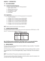
1.3 CALIBRATION MASSES REQUIRED
The masses required to test the EC Series Scales must meet the requirements of ASTM Class 4 or OIML
Class F2. The mass values are listed in Table 1-1.
TABLE 1-1. CALIBRATION MASSES
MODEL Calibration
Cal in kg: Masses Totaling
EC3 3kg
EC6 6kg
EC15 15kg
EC30 30kg
Note: The EC Scales can be calibrated over a wide range, however, it is recommended that the
calibration mass used is at or near the full capacity of the scale for maximum accuracy.
1.4 SERVICE STRATEGY
The repair method for the EC Series Scales is the direct substitution of major assemblies. The available
repair parts are listed in Table 5-1.
The EC Series Scales contains 6 major replaceable assemblies: Top Housing, Membrane Switch, Load Cell
Assembly with Frame, Lead Acid Rechargeable Battery, Display PC Board with LCD and the Main PC
Board.
NOTE: The Load Cell and LCD may also be ordered and replaced separately.
This service manual contains sufficient information to isolate the problem, replace the component, test
and restore the Scale to original factory specifications.

2-1
CHAPTER 2 DIAGNOSIS
2. DIAGNOSIS
This section contains information needed to properly evaluate the reported problem and diagnose its
cause.
2.1 SCALE SETUP AND EXAMINATION
Set up the scale according to the Instruction manual. Allow the scale to stabilize to room temperature.
Examine the scale for signs of corrosion or physical damage.
2.2 PRELIMINARY CHECKS
Power up the scale using the customer’s ac adapter. In the case where the scale will not power up,
check the ac adapter. Observe and record the error codes and software revision. Record all menu settings
as received.
2.3 TROUBLESHOOTING TABLES
Troubleshooting tables 2-1 through 2-7 identify actual types of problems that could be encountered with
the scale.
The troubleshooting tables refer to an interconnection diagram in Section 3 to assist in locating the
problem.
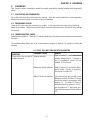
2-1 SCALE WILL NOT TURN ON WITH AC ADAPTER.
SYMPTOM
Scale will not turn on with AC
adapter supplied.
PROBABLE CAUSE
Adapter defective.
Membrane Switch defective.
Main PC Board is defective.
REMEDY
Refer to Section 3.1 and check the ac
adapter voltage output. If voltage is
low or nonexistent, replace the ac
adapter. If OK, proceed.
Refer to Section 3.2 and test the Mem-
brane Switch. Replace if necessary.
See Repair Procedure 4.2
If the scale fails to turn on with a new
Membrane Switch, the Main PC Board
should be tested in accordance with
section 3.4. The Main PC Board if
defective should be replaced. See Re-
pair Procedures 4.3. After repair, pro-
ceed with Performance Tests in Section
3.6.

2-2
CHAPTER 2 DIAGNOSIS
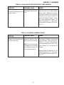
REMEDY
Refer to Section 3.5 and test the battery.
Replace if necessary. See Repair Proce-
dure 4.6.
Refer to section 4.1 and open the scale.
Check voltage at battery contacts first.
Check dc voltage at the battery connector
on the Main PC Board. Voltage should
read approximately 6 Volts dc minimum.
If voltage is not present at the connector,
disconnect the leads from the battery
and make a continuity test between the
connectors on the Harness to the con-
nector on the Main PC Board. Resis-
tance should be 0 ohms for the red lead
and 0 ohms for the black lead. If an open
condition exists, replace wiring and con-
nector as necessary. If OK, proceed.
Refer to Section 3.2 and test the Mem-
brane Switch. Replace if necessary. See
Repair Procedure 4.2
If the scale fails to turn on with a new
Membrane Switch, the Main PC Board
should be tested in accordance with
Section 3.4. The Main PC Board if defec-
tive should be replaced. See Repair
Procedures 4.3. After repair, proceed
with Performance Tests in Section 3.6.
PROBABLE CAUSE
Battery discharged or de-
fective.
Wiring harness defective or
battery clips connection
broken.
Membrane Switch defec-
tive.
Main PC Board is defec-
tive.
SYMPTOM
Scale will not turn on using
battery power.
TABLE 2-2 SCALE WILL NOT TURN ON USING BATTERY POWER.

2-3
CHAPTER 2 DIAGNOSIS
SYMPTOM
Scale does not respond to front
panel controls.
TABLE 2-3 SCALE DOES NOT RESPOND TO FRONT PANEL CONTROLS.
PROBABLE CAUSE
Membrane Switch is defec-
tive.
REMEDY
Refer to Section 3.2 and test the Mem-
brane switch. Replace if necessary.
See Repair Procedure 4.2. If membrane
switches are OK, refer to Section 3.4
and test the Main PC Board. If defec-
tive, replace the Main PC Board. See
Repair Procedures 4.3. After repair,
proceed with Performance Tests in Sec-
tion 3.6.
TABLE 2-4 NO DISPLAY OR PARTIAL DISPLAY.
SYMPTOM
Display is not on or partial char-
acters are displayed.
PROBABLE CAUSE
Display PC Board is defec-
tive or LCD may be defective.
NOTE: If the LCD shows signs
of damage such as cracked,
dim or partial characters, the
LCD should be replaced
REMEDY
The Display PC Board is replaced as a
whole assembly. Check procedures in
Tables 2-1, 2-2 and 2-3 first and verify
that other problems do not exist. Then,
refer to Section 3.6.1 and test the LCD
Display.
Replace Display PC Board or LCD. See
Repair Procedures 4.3.2. After repair,
proceed with Performance Tests in Sec-
tion 3.6.

2-4
CHAPTER 2 DIAGNOSIS
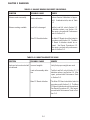
TABLE 2-5 BALANCE READING INCORRECT OR UNSTABLE.
TABLE 2-6 CANNOT CALIBRATE THE SCALE.
SYMPTOM
Balance reads incorrectly.
Balance reading unstable.
PROBABLE CAUSE
Needs calibration.
Load Cell is damaged.
Main PC Board defective.
REMEDY
Perform Service Calibration in Appen-
dix B. If calibration fails, refer to Table
2-6.
Test the Load Cell, refer to Section 3.3.
If defective replace, see Section 4.4.
After repair, proceed with Performance
Tests in Section 3.6.
The Main PC Board should be tested in
accordance with Section 3.4. The Main
PC Board if defective should be re-
placed. See Repair Procedures 4.3.
After repair, proceed with performance
Tests in Section 3.6.
SYMPTOM
Scale can be turned on but will
not calibrate.
PROBABLE CAUSE
Incorrect weights.
Load cell assembly defec-
tive.
Main PC Board defective
REMEDY
Verify that proper weights are used.
Test the Load Cell, refer to Section 3.3. If
defective replace, see Section 4.4. After
repair, proceed with Performance Tests
in Section 3.6.
The Main PC Board should be tested in
accordance with Section 3.4. The Main
PC Board if defective should be replaced.
See Repair Procedures 4.3. After repair,
proceed with Performance Tests in Sec-
tion 3.6.

2-5
CHAPTER 2 DIAGNOSIS
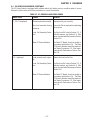
2.4 EC SERIES SCALES ERROR CODE TABLE
The EC Series Scales is equipped with software which will display an error condition when it occurs.
Review the listed codes and follow instructions to correct the problem.
TABLE 2-7. EC SERIES SCALES ERROR CODES
ERROR CODE
E1, E2, E3 displayed
--OL-- displayed
CAUSE
The pan is placed incorrectly.
Zero limit exceeded during
power up.
Load Cell Assembly Defec-
tive.
Main PC Board defective
Load exceeds scale capac-
ity.
Load Cell Assembly Defec-
tive.
Main PC Board defective
REMEDY
Reposition the pan correctly.
Ensure the Pan is empty before switching
the scale on.
Test the Load Cell, refer to Section 3.3. If
defective replace, see Section 4.4. After
repair, proceed with Performance Tests in
Section 3.6.
The Main PC Board should be tested in
accordance with Section 3.4. The Main
PC Board if defective should be replaced.
See Repair Procedures 4.3. After repair,
proceed with Performance Tests in Sec-
tion 3.6.
Reduce the load on the Pan.
Test the Load Cell, refer to Section 3.3. If
defective replace, see Section 4.4. After
repair, proceed with Performance Tests in
Section 3.6.
The Main PC Board should be tested in
accordance with Section 3.4. The Main
PC Board if defective should be replaced.
See Repair Procedures 4.3. After repair,
proceed with Performance Tests in Sec-
tion 3.6.

2-6
CHAPTER 2 DIAGNOSIS

3-1
CHAPTER 3 SCALE TESTING AND CALIBRATION
3. TESTING AND CALIBRATION
This section of the manual contains testing procedures of the individual replaceable components and the
scale. Before and after servicing the EC Series Scales, an operational test and various performance tests
should be made to ascertain whether or not the scale meets specifications.
3.1 TESTING THE AC ADAPTER
The AC Adapters are available with different input voltages. Before testing the Adapter, make sure the
Adapter rating agrees with the power source being used. All Adapters are rated with an output of 12 V dc
at 800mA. Adapters can fail by having shorted internal windings producing low voltage output or no
output at all.
1. Plug the AC Adapter in a suitable power source and measure the open circuit voltage on connector
it should be 10 V dc to 16 V dc.
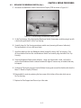
2. Refer to Section 4.1 and remove the Top Housing. Plug the AC Adapter into the scale and
measure the voltage on the battery terminals. Turn the scale on. The voltage should be 6.5 Volts
dc minimum, and 7.5 Volts dc maximum. If the voltage is below or above these readings, replace
the Adapter. This is the actual battery voltage while charging.
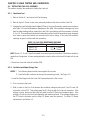
3.2 TESTING THE MEMBRANE SWITCH
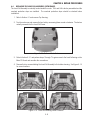
The Membrane Switch can be tested after removing the Top Housing from the Bottom Housing.
1. Refer to Section 4.1 and remove the Top Housing.
2. Disconnect the Membrane Switch connector from the Display PCB.
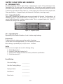
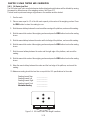
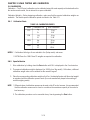
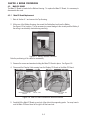
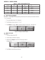
3. Refer to Table 3-1. Using an Ohmmeter, measure the resistance between the pins shown in the
table. The readings should be less than 70 Ohms for each button. If continuity is not present or
the resistance is higher than 100 Ohms, the Membrane Switch is defective. Replace the Membrane
Switch. Figure 3-1 illustrates the cable connector and pin locations.
4. Reassemble Top Housing to Bottom Housing.
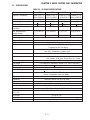
TABLE 3-1. MEMBRANE SWITCH PIN CONNECTIONS.
PANEL BUTTON PINS
SAMPLE 8 to 3
TARE 9 to 3
M+ 6 to1
PT 7 to 1
APW 6 to 2
ZERO 7 to 2
• 9 to 5
C 9 to 4
0 9 to 2
1 8 to 2
2 8 to 5
3 8 to 4
4 7 to 5
5 7 to 4
6 7 to 3
7 6 to 5
8 6 to 4
9 6 to 3
Figure 3-1. Membrane Switch Connector.

3-2
CHAPTER 3 SCALE TESTING AND CALIBRATION
3.3 TESTING THE LOAD CELL ASSEMBLY
This section contains two methods of testing the Load cell.
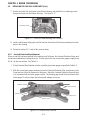
3.3.1 Resistance Test
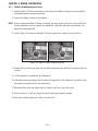
1. Refer to Section 4.1 and remove the Top Housing.
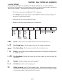
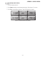
2. Refer to Figure 3-2 and record color code and position of the wires from the Load Cell.
3. Unsolder the Load Cell cable from the Main PC Board. Using an Ohmmeter, measure in accordance
with Table 3-2 Load Cell Resistance Readings on the cable. If the resistance readings vary more
than the table readings allow, replace the Load Cell in accordance with the procedure in Section
4.4 or 4.5. This resistance test is useful in determining if the Load Cell has been severely damaged
by a short or open circuit which has occurred on the cell or wiring. If the Load Cell resistance
readings are good, continue with this procedure.
TABLE 3-2 LOAD CELL RESISTANCE READINGS
MEASUREMENT POINTS READING
Wires 2 & 5 415 + 15 Ohms
Wires 3 & 4 350 + 3 Ohms
NOTE: Wires 2, 3, 4 and 5 must be isolated from chassis ground and shield. Resistance should be
greater than 5 megohms. A lower reading indicates a short in either in the Load Cell cable or the Load
Cell.
4. Reconnect Load cell cable to the Main PCB.
3.3.2 Excitation and Output Voltage Test
NOTES: 1. The following steps involve power applied to the scale.
2. Load Cell solder contacts can be used as measuring points. See Figure 3-2.
1. Insert the Pan Support into the Load Cell Frame and place the Pan on top.
2. Turn on power to the scale.
3. With no load on the Pan, first measure the excitation voltage across point 2 and 5 Load Cell
connection on the PCB. This voltage must be 5.0 Volts dc with the Load cell connected. If the
voltage is lower, disconnect the Load Cell cable from the PC Board and measure again. If the
voltage is 5 Volts dc, the Load Cell is defective and must be replaced. If the voltage remains low,
the PC Board is defective and the Main PC Board must be replaced. For Main PC Board
replacement, see Section 4.3.

3-3
CHAPTER 3 SCALE TESTING AND CALIBRATION
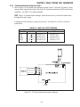
3.3.2 Excitation and Output Voltage Test (Cont.)
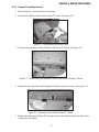
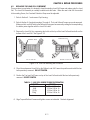
4. Refer to Figure 3-2 and measure the voltages on points 3 and 4, +SIG and –SIG points. These
measurements represent the output of the Load Cell. Repeat measurements at 50% and full scale
capacities. See Table 3-3 for typical readings.
NOTE: Table 3-3 indicates typical readings, actual values can vary, but should remain linear
throughout the entire range.
If readings are out of tolerance, replace the Load cell. See Section 4.4 or 4.5 for Load Cell
replacement.
TABLE 3-3. LOAD CELL OUTPUT READINGS.
NOMINAL OUTPUT IN MILLIVOLTS AT 5 VOLTS EXCITATION
CAPACITY NO LOAD 50% 100%
3 kg 2.7 +1.5 no load + 3.2 no load + 6.4
6 kg 1.9 +1.5 no load + 4.4 no load + 8.8
15 kg 1.2 +1.5 no load + 5.2 no load + 10.3
30kg 0.5 +1.5 no load + 4.9 no load + 10.4
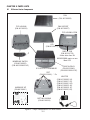
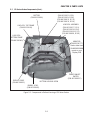
Figure 3-2. EC Series Scales Interconnection Diagram.

3-4
CHAPTER 3 SCALE TESTING AND CALIBRATION
3.4 TESTING THE MAIN PC BOARD
The Main PC Board can be tested by measuring voltages and by using a simulator. The simulator replaces
the Load Cell during testing and is a useful tool for diagnosing problems.
3.4.1 Main PC Board Voltage Measurements
Prior to making the voltage measurements, the battery should have been fully charged and tested.
1. Disconnect power from the scale.
2. Remove the Top housing, refer to Section 4.1 and leave the Membrane Switch connected to the
scale.
3. Disconnect the battery from the Main PC Board.
4. Remove screws and washers holding the Main PC Board and lift the board and lay flat.
5. Connect the AC Adapter to the scale.
6. Refer to Figure 3-2, Interconnection Diagram which illustrates the interconnections to the Main PC
Board and is shown as a top view.
7. Turn the scale on.
8. Using a DVM, measure the excitation voltage across +EXE and -EXE leads it should be 5 volts dc.
This is the excitation voltage for the Load Cell and is regulated. If the voltage is lower, replace the
Main PC Board, refer to Section 4.3 and then proceed with Performance Tests in accordance with
Section 3.6.
9. Measure incoming power from the AC Adapter connector shown in Figure 3-2. The voltage should
read above 6 Volts dc with power on.
10.Connect the battery to the Main PC Board and measure the voltage across Black and Red leads on
the battery connector. The full battery voltage should read a minimum of 6.0 Volts dc. If the voltage
is lower, the battery may require charging or it may be defective. Refer to section 3.5 and test the
battery.
11.Perform simulator testing.

3-5
CHAPTER 3 SCALE TESTING AND CALIBRATION
3.4.2 Simulator Testing
To perform these tests, the use of a Simulator is required. The basic function of a Simulator is to simulate
the output of a full bridge Load Cell allowing the scale to be separated from the Load Cell for the purposes
of troubleshooting and calibration. The Load Cell used in the scale is rated at 2mV/V output with a 5 Volt
excitation voltage applied.
General Load Test
This test checks the Main PC Board circuitry by simulating accurate load cell voltages at 0%, 50% and
100% load capacities.
1. Disconnect power from the scale.
2. Remove the Top housing, refer to Section 4.1 and leave the Membrane Switch connected to the
scale.
3. Disconnect the battery.
4. Unsolder the Load Cell cable from the Main PC Board. Refer to Figure 3-2 for location.
5. With the Simulator set to zero, connect the Simulator test leads to the Main PCB by soldering test
leads in place of the load cell. Make sure connections are correct.
6. Connect a known good AC Adapter to the scale and connect to a power source.
7. Turn on the scale, an error may be displayed. This is normal.
8. Review Table 3-3 and adjust the Simulator to simulate 0% load, 50% load and 100% load for the
rated capacity of the scale. If the resulting readings are unstable, the Main PC Board is defective.
Use the Simulator to calibrate the scale in the next procedure to verify if the Main PC Board is good
or bad.
Calibration Test
This test calibrates the scale using the simulator and can verify that the Main PC Board is functioning
properly or improperly.
1. With the scale on and the Membrane Switch connected, enter calibration mode by pressing and
holding the Zero switch until CAL is displayed and perform calibration.
2. Follow the scale prompts. When the scale indicates a given weight should be placed on the scale,
set the simulator to an equivalent value based on Table 3-3. For example, when a span value of
3 kg for a 3 kg scale is shown, the simulator should be set to output 9.1mV (2.7 + 6.4).

3-6
CHAPTER 3 SCALE TESTING AND CALIBRATION
Calibration Test (Cont.)
3. Upon completion of calibration, the Main PC Board can be further checked using the Simulator to
simulate various weight values. If simulator settings and weight reading on the scale agree, the
Main PC Board is functional. If the scale readings vary, or do not agree with readings in Table
3-3, the Main PC Board is defective and should be replaced.
4. Remove power from the scale and proceed with Section 4.3 and replace the Main PC Board.
5. After Main PC Board replacement and assembly of the scale, proceed with Performance Tests in
Section 3.6.
3.5 TESTING THE BATTERY
The EC Series Scales contains a rechargable, 6.0 Volt, 5.0 Ampere rated, Lead-Acid Battery.
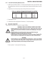
3.5.1 Precautions for Battery Handling
WARNING DEATH OR SERIOUS INJURY CAN OCCUR
•Charge the battery only with the charger in the scale. Charging the battery under any
other conditions may cause the battery to overheat, emit hydrogen gas, Leak, ignite
or burst.
•Operate the battery at normal temperature range as specified for the scale.
•Do NOT short the battery terminals under any conditions.
•Do NOT dispose of the battery in incinerators, or crush or try to open. Dispose of the
defective battery in accordance with local regulations for lead-acid type batteries.
CAUTION
•Check the battery for any sign of irregularities in appearance. If there is any damage
to the case such as cracks, deformation or leakage, replace the battery with a new
one.
•Do NOT charge the battery with the charger terminals reversed.
3.5.2 Battery Tests
A new battery when installed in the EC Series Scales will provide many years of useful service. The length
of service depends upon the type of use of the scale. If left connected to the AC Adapter all of the time, the
battery receives a small charge when the battery voltage is low, service life can be many years.
The EC Series Scales can be operated for up to 80 hours per charge. Battery life can be maximized by
frequent charging.
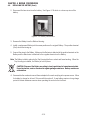
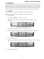
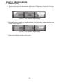
1. Upon receipt of the scale, plug in the AC Adapter to a power source and the scale. Allow the battery
to charge. If the battery required a charge, the battery indicator on the front of the LCD display will
indicate charging. Green indicates fully charged, yellow indicates a partial charge and red,
indicates the battery is nearly discharged.
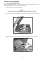
2. Refer to Section 4.1 and remove the Top Housing. Leave the Membrane Switch on the cover
connected to the scale.
Page is loading ...
Page is loading ...
Page is loading ...
Page is loading ...
Page is loading ...
Page is loading ...
Page is loading ...
Page is loading ...
Page is loading ...
Page is loading ...
Page is loading ...
Page is loading ...
Page is loading ...
Page is loading ...
Page is loading ...
Page is loading ...
Page is loading ...
Page is loading ...
Page is loading ...
Page is loading ...
Page is loading ...
Page is loading ...
Page is loading ...
Page is loading ...
Page is loading ...
Page is loading ...
Page is loading ...
Page is loading ...
Page is loading ...
Page is loading ...
Page is loading ...
Page is loading ...
Page is loading ...
Page is loading ...
Page is loading ...
Page is loading ...
-
 1
1
-
 2
2
-
 3
3
-
 4
4
-
 5
5
-
 6
6
-
 7
7
-
 8
8
-
 9
9
-
 10
10
-
 11
11
-
 12
12
-
 13
13
-
 14
14
-
 15
15
-
 16
16
-
 17
17
-
 18
18
-
 19
19
-
 20
20
-
 21
21
-
 22
22
-
 23
23
-
 24
24
-
 25
25
-
 26
26
-
 27
27
-
 28
28
-
 29
29
-
 30
30
-
 31
31
-
 32
32
-
 33
33
-
 34
34
-
 35
35
-
 36
36
-
 37
37
-
 38
38
-
 39
39
-
 40
40
-
 41
41
-
 42
42
-
 43
43
-
 44
44
-
 45
45
-
 46
46
-
 47
47
-
 48
48
-
 49
49
-
 50
50
-
 51
51
-
 52
52
-
 53
53
-
 54
54
-
 55
55
-
 56
56


Ohaus EC Series User manual
- Category
- Kitchen scales
- Type
- User manual
Ask a question and I''ll find the answer in the document
Finding information in a document is now easier with AI
Related papers
Other documents
-
 ANKO Glass Electronic Personal Scale Operating instructions
-
Kmart 43115785 User manual
-
 Teledyne 350, 351, 352, 353, 354, 355 User manual
-
Mettler Toledo JAGXTREME Technical Manual
-
 A & A Scales PT300 User manual
-
Vishay VT300 Technical Manual
-
-
 Avix SUPERCHARGER 60 R3.0 60 R3.0 User manual
-
-
Digi DC-190 User manual


