
305001-002-101-102 G20E 1
INSTRUCTIONS FOR
INSTALLATION, USE & MAINTENANCE
STOVE TOP Series 0200
MODELS: 0202(P), 0204(P), 0206(P),
(305001-305101) 0201/K(P), (305002-305102) 0202/K(P), 0203/K(P)
202ST(P), 204ST(P), 206ST(P),
751ST(P), 752ST(P), 753ST(P), ST2(P), ST4(P), ST6(P)
204STV(P), 206STV(P), 204STVE(P), 206STVE(P), 206STVBE(P)
ADJUSTED FOR: (I3+) G-30/G31 28-30/37 mbar
ATTENTION: USE ONLY IN WELL VENTILATED PLACES
READ CAREFULLY & SAVE THIS INSTRUCTIONS MANUAL, BEFORE
INSTALLATION & USE OF THE APPLIANCE
Directive 2009/142/EC
UNE-EN 203-1 :2014, UNE-EN 203-2-1, UNE-EN 203-2-2

2 305001-002-101-102 G20E
1 2 3 8
5 4 6 7
FIG. A

305001-002-101-102 G20E 3
FIG. D
FIG. C (BURNER 200E)
FIG. C1
FIG. C
FIG. B

4 305001-002-101-102 G20E
Operating Instructions
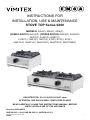
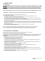
Description STOVE TOP Fig. A
1. Body
2. Grate
3. Burner
4. Thermomagnetic Valve
5. Knobs
6. Injector Cover
7. Drawer
8. Adjustable Feet
9. Thermocouples
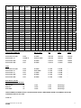
TECHNICAL SPECIFICATIONS
CATEGORIES: I2H, I2E, I2E+, I3B/P, I3+, II2H3+, II2H3B/P 50mbar, II2E+3+,
II2E+3B/P, II2E3B/P
COUNTRY CATEGORY GAS PRESSURE
AT Austria I2H G-20 20 mbar
"I3B/P G-30/G-31 50 mbar
BE Belgium I2E+ G-20 20/25 mbar
"I3+ G-30/G-31 28-30/37 mbar
DK Denmark I2H G-20 20 mbar
"I3B/P G-30/G-31 30 mbar
FI Finland I2H G-20 20 mbar
"I3B/P G-30/G-31 30 mbar
FR France I2E+ G-20 20/25 mbar
"I3+ G-30/G-31 28-30/37 mbar
"I3B/P G-30/G-31 50 mbar
DE Germany I2E G-20 20 mbar
"I3B/P G-30/G-31 50 mbar
GR Greece I2H G-20 20 mbar
"I3+ G-30/G-31 28-30/37 mbar
IE Ireland I2H G-20 20 mbar
"I3+ G-30/G-31 28-30/37 mbar
IT Italy I2H G-20 20 mbar
"I3+ G-30/G-31 28-30/37 mbar
NL Netherlands I3B/P G-30/G-31 30 mbar
PT Portugal I2H G-20 20 mbar
"I3+ G-30/G-31 28-30/37 mbar
ES Spain I2H G-20 20 mbar
"I3+ G-30/G-31 28-30/37 mbar
SE Sweden I2H G-20 20 mbar
"I3B/P G-30/G-31 30 mbar
GB United Kingdom I2H G-20 20 mbar
"I3+ G-30/G-31 28-30/37 mbar

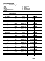
305001-002-101-102 G20E 5
Model
Dimensions
cm
Burner
Type
Pan
Diameter mm
G20 20mbar
2nd fam. H,E,E+
G-25 25mbar
2nd fam. L
G-30 28-30mbar
3rd fam. 3+
G-31 37mbar
3rd fam. 3+
G-30 50mbar
3rd fam. B/P
G-31 50mbar
3rd fam. B/P
-ΣQn-
kW(Hi) m3/h -ΣQn-
kW(Hi) m3/h -ΣQn-
kW(Hi) g/h -ΣQn-
kW(Hi) g/h -ΣQn-
kW(Hi) g/h -ΣQn-
kW(Hi) g/h
0202(P) 38x70x20 200 20-35 12.54 1.26 13.80 1090 12.60 982 13.28 1050 11.78 920
0204(P) 71x70x20 200 20-35 25.08 2.52 27.6 0 2180 25.20 1964 26.56 2100 23.56 1840
0206(P) 104x70x20 200 20-35 37.6 2 3.77 41.40 3270 37.80 2946 39.84 3140 35.34 2750
0201K(P) 36,5x40x20 200 20-35 6.27 0.63 6.90 495 6.30 541 6.64 525 5.89 460
0202K(P) 71x40x20 200 20-35 12.54 1.26 13.80 1090 12.60 982 13.28 1050 11.78 920
0203K(P) 104x40x20 200 20-35 18.81 1.89 20.70 1635 18.90 1453 19.92 1570 17.67 1370
202ST(P) 40x70x85/25 200 20-35 12.54 1.26 13.80 1090 12.60 982 13.28 1050 11.78 920
204ST(P) 80x70x85/25 200 20-35 25.08 2.52 27.6 0 2180 25.20 1964 26.56 2100 23.56 1840
206ST(P) 120x70x85/25 200 20-35 37.62 3.77 41.40 3270 37.80 2946 39.84 3140 35.34 2750
751ST(P) 40x70x430 200 20-35 12.54 1.26 13.80 1090 12.60 982 13.28 1050 11.78 920
752ST(P) 80x70x430 200 20-35 25.08 2.52 27.60 2180 25.20 1964 26.56 2100 23.56 1840
753ST(P) 120x70x430 200 20-35 37.6 2 3.77 41.40 3270 37.80 2946 39.84 3140 35.34 2750
ST2 34,5x80x24 200 20-35 12.54 1.26 13.80 1090 12.60 982 13.28 1050 11.78 920
ST4 90x80x24 200 20-35 25.08 2.52 27.60 2180 25.20 1964 26.56 2100 23.56 1840
ST6 134,5x80x24 200 20-35 37.62 3.77 41.40 3270 37.80 2946 39.84 3140 35.34 2750
204STV(P) 80x70x98,5 200 20-35 33.35 3.32 35.20 2780 32.80 2556 34.36 2715 30.76 2391
206STV(P) 120x70x98,5 200 20-35 45.89 4.57 49.00 3870 45.40 3538 47.6 4 3755 42.54 3311
204STVE(P) 80x70x98,5 200E 14-35 32.80 3.29 30.80 2430 30.80 2400 32.60 2572 30.40 2368
206STVE(P) 120x70x98,5 200E 14-35 45.20 4.53 42.40 3345 42.40 3303 45.00 3550 42.00 3272
206STVBE(P) 91x80x96,5 200 20-35 45.89 4.57 49.00 3870 45.40 3538 47.64 3755 42.54 3311
INJECTORS DIAMETER Burner Type: 200 200E OVEN
Gas 2nd fam. H,E,E+ G-20 20 mbar: 1.90 mm 1.90 mm 2.20mm
Gas 3rd fam. 3+ G-30/G-31 28-30/37 mbar: 1.25 mm 1.25 mm 1.45mm
Gas 3rd fam. B/P G-30 50 mbar: 1.15 mm 1.15 mm 1.35mm
Gas 3rd fam. B/P G-31 50 mbar: 1.15 mm 1.15 mm 1.35mm
Qmin
Gas 2nd fam. H,E,E+ G-20 20 mbar: 1.7 kW 2.4 kW -
Gas 3rd fam. 3+ G-30 28-30 mbar: 1.7 kW 2.4 kW -
Gas 3rd fam. 3+ G-31 37 mbar: 1.7 kW 2.4 kW -
Gas 3rd fam. B/P G-30 50 mbar: 1.7 kW 2.4 kW -
Gas 3rd fam. B/P G-31 50 mbar: 1.7 kW 1.5 kW -
Pilot Burner: 0,2 kW
PRIMARY AIR REGULATOR (d)
Natural Gas: d= 8 mm 7 mm No Change
GLP I3+: d= 11 mm 6 mm No Change
GLP I3B/P: d= 11 mm 7 mm No Change
OVEN PRIMARY AIR REGULATOR: THIS APPLIANCE DOESN’T NEED REGULATING THE PRIMARY AIR AFTER
CHANGING THE GAS YOU USE.
TYPE: A1

6 305001-002-101-102 G20E
A. INSTALLATION
A.1. Warning
WARNING: THIS APPLIANCE MUST BE INSTALLED BY A SPECIALIST TECHNICIAN ACCORDING TO THE LAWS
AND REGULATIONS IN FORCE IN THE COUNTRY OF DESTINATION, IN WHICH THE APPLIANCE WILL BE USED
WARNING: THIS APPLIANCE MUST BE INSTALLED ONLY IN WELL AND SUFFICIENT VENTILATED SPACES TO
PREVENT THE OCCURRENCE OF UNACCEPTABLE CONCENTRATIONS OF SUBSTANCES HARMFUL TO HEALTH
THERE A SERIOUS HEALTH RISK IF THIS APPLIANCE IS USED IN PLACES WITH INADEQUATE VENTILATION.
FIRE DANGER – THE AREA AROUND THE APPLIANCE MUST BE FREE AND CLEAN FROM FUEL.
For technical support address to the manufacture authorized service.
Ask for the genuine spare parts.
-The appliance must only be used by trained sta and must be supervised at all times when in use.
-Switch o the appliance if it breaks down or malfunctions.
-Do not use products containing chlorine (bleach, hydrochloric acid etc.) even diluted, to clean steel surfaces.
-Do not leave dirt, fat, food or other products to dry on the appliance.
-This appliance is intended for industrial use only and is specically designed to cook food. Any other use of the
appliance is deemed improper.
-Only contact the technical service centre authorized by the manufacturer for repairs and only use original spare
parts. Failure to comply with the above requirement may jeopardize the safety of the appliance and render the
guarantee null and void.
-Do not use corrosive substances (i.e. muriatic acid) to clean the oor under the appliance.
-Do not wash the appliance with water jets
NOT FOLLOWING THE ABOVE INSTRUCTIONS MIGHT AFFECT THE SECURITY OF THE APPLIANCE.
NOT FOLLOWING THE ABOVE INSTRUCTIONS CAN CAUSE THE GUARANTEE’S DEDUCTION.
A.2. Safety Rules for Installation
This appliance cannot be connected to a duct for removing the products of combustion.
Particular care must be taken with the ventilation systems you use.
The installation, connection and maintenance must be undertaken only by a specialist technician, taking
into account all the present instructions, as well as the remaining provisions concerning the site of
installation:
-Examine the packaging before and after the uploading.
-An adequate ow of air in and out of the area is needed
-A window, opening to at least 0.40m² is required
-The installation, use and maintenance of this appliance by children is strictly prohibited. Keep children and
curious onlookers away when the appliance is in operation.
-The appliance must be installed on a horizontal surface, with a constant heat resistance of at least 90º C. All
ammable surfaces are prohibited.
-A space of 0.20m must be left around the appliance for ventilation.
-This appliance is not suitable for built –in installation.
-Carefully remove the protective lm from the external panels to avoid leaving any trace of glue.
-Use a suitable diluents to remove any glue residue.
-Is strictly forbitten to place objects or food on the top of the appliance.
-Don’t hang anything over the appliance closer than 1,5m. Leave always the space of 1,5m empty over the
appliance because the heat from the exhaust duct is very high.
-Do not place anything in front of the appliance at a distance of less than 1.5 meter, because the temperature in
front of the open door is very high.
-Installation and use of this appliance in basement areas is prohibited.

305001-002-101-102 G20E 7
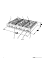
A.3. Connection
The appliance may be connected in three ways, depending on the type of gas to be used. The connection point (4),
Figure C, between the appliance and the gas supply is situated at the bottom (or the back) of the appliance.
A rapid- action gas shut -o cock must be tted upstream of each appliance in an easily accessible position.
Once the appliance has been installed, check for gas leaks at connection points using a soapy water solution.
ATTENTION: In case of use for the gas supply connection of the appliance a exible tube or hose, this shall
comply with the national requirements and shall be periodically inspected and replaced as necessary.
This appliance must be connected for gas supply only with approved exible hoses or tubes. Their length should
not exceed 1.5m and it is forbidden to twist them.
A.3.1 Use of the Appliance with Butane & Propane
Butane: Use an approved low pressure regulator 28 – 30mbar
Propane: Use an approved low pressure regulator 37mbar
In this case, you may use the connection nozzle (1), Figure B, which accompanies the appliance, to connect it with
a exible pipe.
Screw the nozzle on the bottom (or the back) of the appliance, to the gas connection port (4), with a diameter of 16
mm (3/8).
This pipe must be approved for this use.
You must check the date of replacement of the pipe. You must install it in such a way that it is visible along the
whole length (from the appliance to the supply tap or to the bottle).
The connections must be checked for leaks in order to avoid gas escaping, with the help of soapy water.
To do so: open the bottle or the supply-tap, to allow the gas to circulate, and ensure that the connection is correct
by checking for air bubbles in the soapy water spread over the connections.
DANGER: THE USE OF A FLAME TO CHECK FOR LEAKS AT CONNECTION POINTS IS STRICTLY
FORBIDDEN.
A.3.2 Use of the Appliance with Natural Gas
Connection may be made with the help of the nozzle (2), Figure B, when a exible pipe is to be used, following the
instructions on the previous paragraph with regard to connection and checking for leaks.
If you wish to make a permanent, xed connection with a hard pipe screwed into position, it will be necessary to
use the nozzle (3), Figure B. This is the recommended type of connection.
DANGER: THE USE OF A FLAME TO CHECK FOR LEAKS AT CONNECTION POINTS IS STRICTLY
FORBIDDEN.
A.3.3 Use of the Appliance with Propane & Butane 50 mbar
Butane: Use an approved low pressure regulator 50mbar
Propane: Use an approved low pressure regulator 50mbar
Connection may be made with the help of the nozzle (1), Figure B, when a exible pipe is to be used, following the
instructions on paragraph 3.1, with regard to connection instructions and checking for leaks.
If you wish to make a permanent, xed connection with a hard pipe screwed into position, it will be necessary to
use the nozzle (3), Figure B. This is the recommended type of connection.
DANGER: THE USE OF A FLAME TO CHECK FOR LEAKS AT CONNECTION POINTS IS STRICTLY
FORBIDDEN.

8 305001-002-101-102 G20E
A.4. Adaptation for Gas Change
All appliances, on delivery, are factory adjusted for use with Propane 37 mbar (G31) or Butane 28-30mbar (G30).
However, it is necessary to determine whether the low pressure regulator you are using is approved for 37 mbar for
Propane or 28-30mbar for Butane, respectively.
In case the appliance is to be used with natural gas, or with Propane and Butane at a pressure of 50 mbar, the
following adjustments must be made after installation, only by a specialist technician, as explained on paragraphs
4.1, 4.2, 4.3 and 4.4:
-change of injectors
-change of injector of the Oven pilot burner
-adjustment of the ow of air into the burner
-adjustment of the thermomagnetic gas valve of each burner to the position ‘minimum’ ( , small ame)
After the change of the injector and the air regulation, in order to obtain the gas changes it’s necessary
to put a mark on the data plate which is placed on the body of the appliance to indicate the new gas
regulation.
A.4.1 Change of Injectors
The following procedure must be done having the gas supply closed:
To change the injectors on the top burners, you must rst remove the grates (2) and unscrew the injector cover (5)
of the appliance Fig. A. You must remove the burners by unscrewing the two screws under the burner that keep
them into position. The injectors may then be changed. At the edge of each thermomagnetic gas valve (1) Figure
C, are the injectors (2). With a number 7 spanner, or a special screwdriver number 7, unscrew the injectors and
replace them with the injectors you will nd in the appliance packaging, either those marked ‘Natural Gas’ or those
marked ‘Ι3 B/P: 50 mbar’, depending on the gas you are using.
To change the injectors on the oven burner:
-Open the oven door, remove the griddles and the metallic surface situated on the bottom of the oven chamber
by pulling up using the hole at the front part.
-By using a screwdriver, loosen up the two screws and the remove the cover of the burner.
-With a number 13 spanner, unscrew the injector (2) Fig C’ and replace it with the injector you will nd in the
appliance packaging, either this marked ‘Natural Gas’ or this marked ‘Ι3 B/P: 50 mbar’, depending on the gas
you are using.
A.4.2 Change of the injector of the Oven pilot Burner
The following procedure must be done having the gas supply closed.
After changing the burner injector you have to change also the pilot burner injector which are located next to the
main burners.
By using a screwdriver, loosen up the two screws and the remove the cover of the burner of the appliance
according the paragraph A.4.1
With No 11 unscrew the back-end cover of the pilot (12) g. E and by using a screwdriver replace the injector inside
the body of the pilot.
Place again the cover with a spanner no 11 and put all the parts on place.
WARNING: It is strictly forbidden to modify the entrance of the combustion air differently from the
indicated in this Instruction Manual as well as the combustion products evacuation.
A.4.3 Adjustment of the Flow of Primary Air into the Burner
The following procedure is followed, having the gas supply closed. The ow of air into the top burners must
be adjusted using the ring (3), Figure C, sited on the burner and supported with a screw (4). Loosen the screw (4),
place the ring in a position such that the distance d=8 mm, for Natural Gas and d=11 mm for the ‘Ι3 B/P: 50 mbar’.
Tighten the screw (4) again so that the ring (3) is properly secured on the burner.

305001-002-101-102 G20E 9
Put the burners back into position, taking care to position them correctly and replace the screws that have been
removed. Replace the injector cover and the grates of the appliance.
WARNING: It is strictly forbidden to modify the entrance of the combustion air differently from the
indicated in this Instruction Manual as well as the combustion products evacuation.
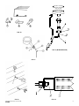
A.4.4 Adjustment of the Thermomagnetic Gas Valve of each
Top Burner to the ‘Minimum’ position ( , small ame)
The following procedure is followed after the procedures referred to on paragraphs 4.1 and 4.3 are completed.
All thermomagnetic gas valves of the top burners must be adjusted. After the appliance has been installed and
connected according to the above instructions, light the burner according to the instructions on paragraph B.2
Ignition.
Turn the thermomagnetic valve knobs (1), Figure D, to the ‘Minimum’ position ( , small ame) and then pull them
out. The adjustment screw is sited in the hole (2), right above the thermomagnetic gas valve. Using a very small
screwdriver, 2 mm wide, adjust the intensity of each burner. Do not forget to keep all the gas valves at the minimum
(, small ame) position. Turning the screwdriver to the left, the ame gets larger, and to the right, the ame gets
smaller, as shown in Figure D. The appliance is properly adjusted when you see a small, steady, blue-colored
ame on the burner. Replace the valve knobs (1) and then turn the appliance o, by turning the knobs back to the
position ().
A.5 EQUIPOTENTIAL TERMINAL:
This terminal at the bottom or the back of the appliance is only for connecting two or more appliances
together with an equipotential node.
B. USE
B.1. Safety Rules for Use
WARNING: THIS APPLIANCE MUST BE USED ONLY IN WELL VENTILATED PLACES
WARNING: IT’S STRICTLY FORBIDDEN TO OPEN THE DOOR WHEN THE OVEN IS HOT. THERE IS DANGER OF
BURN ON YOUR FACE AND HANDS, BECAUSE OF THE HOT AIR THAT GOES OUT THE MOMENT OF THE DOOR
OPENING.
WARNING: IT IS STRICTLY FORBIDDEN TO PLACE ANY COMBUSTIBLE MATERIAL IN FRONT OF THE
APPLIANCE IN A DISTANCE LOWER THAN 2,00 METERS, OR ABOVE OF IT.
WARNING: TO REDUCE CONSUMPTION OF GAS, DO NOT USE THE APPLIANCE EMPTY OR IN CONDITION
THAT COMPROMISE OPTIMAL EFFICIENCY (E.G. WITH THE DOOR OR LIDS OPEN ETC.) WHENEVER
POSSIBLE, PREHEAT ONLY BEFORE USE.
WARNING: THIS APPLIANCE IS DESTINED FOR PROFESSIONAL USE ONLY AND MUST BE USED BY SKILLED
PERSONNEL
WARNING: IT’S STRICTLY FORBIDDEN TO CLOSE THE EXHAUST DUCT ON THE TOP OF THE APPLIANCE
WARNING: KEEP EMPTY THE FAT COLLECTOR OR ANY RECEPTACLE PAN YOU MIGHT USE FOR THE
COLLECTION OF THE FATS ON THE LOWER PART OF THE APPLIANCE IN ORDER TO AVOID RISK OF FIRE,
DUE TO OVERHEATING.
WARNING: KEEP CLEAN THE COOKING CABINET AND SPECIALLY THE BOTTOM, OF THE APPLIANCE,
WHERE FAT MAY ACCUMULATE FREQUENTLY, IN ORDER TO AVOID RISK OF FIRE, DUE TO OVERHEATING.
-The appliance must be used exclusively for the intended purpose, for cook food and boiling food by casseroles,
pans, frying pans. Any other use is considered improper.
Placing food directly on the appliance is strictly forbidden.
Installation, use and maintenance of this appliance by children is strictly prohibited. Keep children and curious
onlookers away while the appliance is in operation.
Clean the parts of the appliance where fat may accumulate, frequently, in order to avoid fat inammation, due to
overheating.
Pouring liquids (e.g. fat, water, sauces etc.) on the appliance is strictly forbidden.
Frequently empty the fat-collector drawer.
The minimum diameter of the casseroles, pans, frying pans etc that can be used for cooking is 140 mm and the
maximum diameter is 350mmdepending of the model. See Table on page 5.

10 305001-002-101-102 G20E
B.2. Ignition
Having connected the appliance according to the above instructions, open the gas supply to the appliance.
TOP BURNERS: Each of the top burners (3) Figure A, has its own thermomagnetic valve knob (4), which adjusts
its intensity. The appliance is delivered with the thermomagnetic valve knobs of the burners closed, that is to the
() position. When you wish to start the appliance, with one hand press down and turn the thermomagnetic valve
knob (4), to the left, to the position (). With the other hand approach a lit conventional lighter to the burner, until
the burner is ignited.
Continue holding the thermomagnetic valve knob (4) pressed down for about 5” seconds. In case the burner fails to
light, repeat the above procedure.
You can now ignite the other burners, by repeating the above procedure.
Adjust the level of each burner to your preference, slowly turning the valve knobs (4) towards the ‘minimum’
position with the symbol ( , small ame).
The high or low temperature of the burners is achieved by turning the thermomagnetic valve knobs either to the left
or to the right.
B.3. Turning O
To turn the top burners o, turn all the thermomagnetic valve knobs(4) to the position (), so that the burners go
out, too.
To turn the oven o, turn the valve knob (7) to the (*) position, so that the burner shut down.
To turn the pilot burner o, you must press and turn knob (7) to the () position (or-depend to the valve- you must
push the button (8) of thermostatic valve with the symbol ().
The appliance is then turned o.
B.5. Ventilation
During cooking, smoke and steam is given o . Therefore, the site where the appliance is used must be properly
ventilated by opening a window or with the help of a special ventilation mechanism (extractor fan).
Warning: Care must be taken never to cover the oven exhaust grid (2) Figure A.

305001-002-101-102 G20E 11
C. CLEANING & MAINTENANCE
REGULAR CLEANING HELPS THE PROPER AND BETTER OPERATION OF THE APPLIANCE.
WARNING: KEEP CLEAN ALL THE PARTS OF THE APPLIANCE AND THE COOKING CABINET - SPECIALLY THE
BOTTOM - OF THE APPLIANCE, WHERE FAT MAY ACCUMULATE FREQUENTLY, IN ORDER TO AVOID RISK OF FIRE,
DUE TO OVERHEATING.
During cleaning, the appliance as well as the gas supply should always be turned off.
-Do not wash the appliance with water jets.
-Wait for the oven chamber to cool
-Clean stainless steel surfaces with warm water and soap, rinse and dry thoroughly.
-Our appliances are manufactured using metals (stainless steel, mild steel, zinc plated sheet metal etc) and can
therefore be recycled in conventional waste recovery sites in compliance with current standards in the country
of installation.
-To minimize the emission of pollutants into the environment, we recommend cleaning the appliance externally
and, where necessary, internally with products which are at least 90% biodegradable.
-You can easily remove the grates and the fat-collector drawer for cleaning.
-Remove the cabinet Griddles and large baking Pan and all their accessories for cleaning, by simply drag them
out.
-You can wash them with brand-name cleaning products, approved of use on surfaces that comes in touch with
food.
-Always rinse with plenty of water and dry before use.
Replace correctly all the above accessories that were removed for cleaning.
The appliance is ready to be used again.
D. LIST OF SPARE PARTS & GREASING (Fig. A & E)
Thermomagnetic gas valve (4, Fig A): Has to be changed when you notice a malfunction on the rotation of the
axe (sti, bent, ect.) or when you notice leak of gas near the axe, or the body of the valve.
Thermostatic gas valve (1, Fig E): It has to be changed when you notice that it doesn’t regulated correctly the
temperature oven, or when you notice a gas leak near the axe or the body of the valve.
Magnet Unit: It is placed inside the thermostatic gas valve. It has to be changed when you notice that it is not
possible for the pilot to stay lit after you light it up, but only if you are sure that the thermocouple is working properly
and is well screwed.
Thermocouple (9, Fig E): Has to be changed when you notice that it is not possible for the burner or the pilot to
stay lit after you light it up.
The grades(2, Fig A): They have to be changed when they are deformed or broken, so the cooking utensils
(casseroles or pans) are stable.
The burner (5, Fig E): It has to be changed when you notice that some of the holes have become bigger or
deformed, the surface is damaged, the whole burner is broken or it is very dirty.
The high voltage cable (11, Fig E) of the spark plug: It has to be changed when you notice that it is not possible
to create a spark when you press the piezoelectric igniter, although the spark plug is working properly.
The pilot (12, Fig E): It has to be changed when you notice that it is not possible to be lit, or the ame is not
correct (the color must be blue), because of the fats.
Piezoelectric igniter (13, Fig E): It has to be changed when you press it and it is not possible to create a spark,
although the spark plug and the high tension cable are correct.
The spark plug (16, Fig E): It has to be changed when you notice that it is not possible to create a spark when
you press the piezoelectric igniter, although the connection of the cable is correct.
-Door Isolation Rubber: It must be replaced when it is deformed, cut or destroyed resulting in incorrect closing
of the door and, therefore, leakage of temperature.
-Removable griddles-pans: They Must be replaced when are deformed, broken or very dirty because they can
be dangerous for the food and for the user.

12 305001-002-101-102 G20E
ATTENTION: The above cases should be handled only by specialized technicians.
ATTENTION: It’s strictly forbitten to touch, to regulate or repair the internal part of the thermomagnetic gas valve,
the gas tubes and the burners that is located inside the metallic body (1), under the grades (2) of the machine
Fig A, or under the cooking cabinet of the oven.
INSPECTION: The gas supply tubing or hose used for the connection of the appliance, shall comply with the
national requirements in force and it shall be periodically inspected every month, for gas leaks and their good
condition and be replaced if necessary.
INSPECTION: The function of the machine and the good condition of all the parts must be inspected every
month. Specially, the blue color of the ame of the top burners must be inspected every day. The stability of the
casseroles and the pans on the grades must be inspected every month. In case of deformation the grates must
be replaced. The smooth rotation of the knobs of the valves must be inspected daily and to be replaced in case of
malfunction or gas leak. Also, the good condition of the inside surface of the cooking cabinet of the oven and the
griddle gliders, must be inspected every day if they are cleaned, broken or damaged.
INSPECTION & GREASING: The thermomagnetic gas valve must be inspected for inside greasing, once per year
but only by specialized technicians.
BE IN CONTACT WITH VIMITEX FOR DETAILED INSTRUCTION.
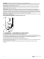
E. ASSEMBLING – DISASSEMBLING SPARE PARTS
The following procedure is followed having the gas supply closed.
To change the thermocouple, gas tap, burner or the injector of the oven you must rst remove the bottom of the
cooking cabinet (11) of the appliance (1) Figure A-Oven. Afterwards, you unscrew the 4 screws that holds the cover
on the left external side panel, that helps you to have an easier access on the valve and the tubing.
For the changes you can follow the instructions of the chapter A4.
To replace a burner (5), Fig. D, you must unscrew the two screws that hold it.
After the changes, you place back the cover on the left external side panel (1) Figure A and afterwards the bottom
of the cooking cabinet (11) in its place.
The above cases must be undertaken only by a specialist technician, taking into account all the present
instructions.
-
 1
1
-
 2
2
-
 3
3
-
 4
4
-
 5
5
-
 6
6
-
 7
7
-
 8
8
-
 9
9
-
 10
10
-
 11
11
-
 12
12


Ask a question and I''ll find the answer in the document
Finding information in a document is now easier with AI
Related papers

Other documents
-
MAINSTREET EQUIPMENT 541E24L User manual
-
-
GGM Gastro GM636E-B Owner's manual
-
Drija FERRARA 90 User manual
-
Drija FERRARA 76 User manual
-
Master Appliance PORTAPRO GG-100 User manual
-
PARRY PO20 Owner's manual
-
Sammic AG-40 User manual
-
RAIS Visio Gas 70-43-39 LC Installation guide
-
Arada S3 Ecoburn Gas Medium User guide