Page is loading ...

www.AKCP.com
SP2+ Introduction Manual
Copyright © 2022, AKCP

SP2+ Introduction Manual - updated firmware 5824
- 2 -
Table of Contents (please use the Ctrl F “search” for locating the exact sections & pages)
Introduction .............................................................................................................................................
Port assignment information for SP2+ units & ports locked info..........................................................
LED information for SP2+ units ..............................................................................................................
Reset button functions for SP2+ units ...................................................................................................
Setting up the unit’s IP address & troubleshooting - Dual Power Input Options .................................
SP2+ Web UI Walkthrough ......................................................................................................................
Menu navigation ..........................................................................................................................
Monitoring Summary page .........................................................................................................
Graph feature ..................................................................................................................
Expansion units ..............................................................................................................
Managing Desktops and rack Maps (& Map Feature on F7/H7) ................................................
Important Notes on custom desktops ...........................................................................
Managing Desktops ........................................................................................................
Navigation
Folders
Desktops
Adding items to your custom desktop
Desktop Auto Scroll feature
Managing Rack Maps .....................................................................................................
Access Control Users and Groups.............................................................................................
Notifications and Events, Sensors menu, Settings menu .........................................................
System page ................................................................................................................................
General
Language management
Date/Time
Network
Modem
VPN
Set up VPN connection to APS (AKCPro Server)
SMTP (setup for gmail & office365)

SP2+ Introduction Manual - updated firmware 5824
- 3 -
SNMP
Server Integration
Services
SSL Certificate
Modbus
Password Checking and security
Password Security options
Maintenance (create support files & backups etc.)
Heartbeat Messages
License Management
About
Sensor’s page .............................................................................................................................
General options for all sensors
Virtual sensors
Example sensor configuration
Temperature/Humidity Sensor
Relay Sensor
Firmware upgrade through the Web UI ......................................................................................
Network ports used by SP+ units ...........................................................................................................
FCC Statement………………………………………………………………………………………………………..

SP2+ Introduction Manual - updated firmware 5824
- 4 -
Introduction
In this manual, we’ll cover the main features and basic configuration of the SP2+ and the setup of
notifications and the explanation of events will be in the “Notifications” manual. Please also see our
Knowledge Base page here: https://www.akcp.com/knowledge-base/sensorprobe-plus-series-
knowledge-base/
What is the SP2+?
The SP2+ is a high speed, accurate, intelligent monitoring device, featuring a completely embedded
host and operating system. The SP2+ is a complete redesign of the world’s best-selling
environmental monitoring platform, 3 years in the making with all new hardware and software.
We’ve combined the low cost and simplicity of use of the SP2, along with many advanced features of
our securityProbe platform.
The SP+ units support a maximum of 150 sensors (data points) per unit. This unit supports up to 4
(physical) sensors (with the 4PUN unlock code explained below).
SP2 + Features:
● IP based, including SNMPv3, HTTPS, VPN
● Send encrypted SNMP Trap and Email Notifications
● Supports 4 Intelligent Sensors or up to 20 Dry Contacts (with unlock codes)
● Optional cellular modem with external antenna
● Notification Wizards
● Front and Rear Thermal Mapping for any server cabinet
● Optional Expansion Module connectivity
● Virtual Sensors
● AKCP Swing Handle Lock support
Please check all the specifications & features on our SP2+ datasheet:
https://www.akcp.com/support-center/media-pack/
Important notes:
A) Some of the pictures shown in this manual might not represent the actual Web UI of the unit; this is
because we are constantly working on improving the firmware. Please provide us with feedback if you
have any issues configuring your unit.
B) All SP+ H7 type units with firmware version 1.0.5824 are now shipped with DHCP enabled
by default. See below beginning on page #10 for more details. If you do not use DHCP on your
network, the unit will revert to the fixed IP address of 192.168.0.100. Please see the section in this
manual on how to setup a new IP address on the unit. The SP+ F4 & F7 type units will not be
affected.

SP2+ Introduction Manual - updated firmware 5824
- 5 -
C) AKCP also always highly recommends using a dedicated 3rd party UPS on the units. Any
damage caused by unstable power or power outages will void the warranty on our units.
What’s the difference between the SP2+ and SPX+?
The SP2+ has 4 sensor ports for connecting any compatible AKCP sensor. With the Expansion option
it has 3 sensor ports and 1 expansion port.
The SPX+ also supports expansion modules and has modular design allowing you to choose your
own configuration.
We have several standard configurations, but with the AKCP Configuration Tool you are able to
custom design a unit to your own specifications. See below for available modules to choose from.
What’s the difference between F4 (older) F7 & H7 (newer) processor versions?
The F4 SP+ & the F7 & H7 SP+ processors - or as we will refer to them as platforms are different.
The new F7 & H7 processor or platforms support more memory on the SP+ (SP2+ and SPX+) units,
thus more features. Future firmware development will concentrate on the H7 units. The F4 & F7 units
will not support new features.
The most notable difference between the platforms is the supported number of sensors when the
VPN feature is enabled: the total sensor count is reduced to 36 on F4 units, but it is still 150 on F7 &
H7 units.
When upgrading the firmware, there are three separate .bin files included in the firmware update
packages. One for the F4 units, one for the F7 units and one for the H7 units.
If you try to upgrade your unit with the wrong .bin file, the firmware upgrade will fail. So please make
sure you use the correct file for your unit type following the firmware upgrade instructions in the text
file that is included in the compressed firmware package.
Also, very important to note that any backup configuration created on the F4 platform cannot be
uploaded to the F7 platform unit and vice versa. This also applies to the H7 units. Backup
configurations created on the F7 units are compatible with the H7 units (only SP2+ to SP2+).
F7 Units Specifications:
AKCP STM32F7 MCU
32-bit ARM micro-processor
512KB of Ram
32MB of non-volatile flash
H7 Units Specifications:
AKCP STM32H7 MCU
32-bit ARM micro-processor
1MB of RAM
64MB of non-volatile flash

SP2+ Introduction Manual - updated firmware 5824
- 6 -
CPU speed: 216 MHz (F7) to 460 MHz (H7) The H7 is significantly faster than the F7 in real usage.
In the SP+ units web UI you will be able to view which platform the unit is using.
This can be checked in the Settings >> General page >> System Description:
And in the Settings >> About page >> System Description:

SP2+ Introduction Manual - updated firmware 5824
- 7 -
Port assignment information for SP2+ units
Port numbering starts from the power connector on the unit: the closest port to the power connector is
Port 1 and closest to the Ethernet interface is Port 4.
You may connect AKCP intelligent sensors to any available ports.
Important notes:
• The power adapters that are used on sensorProbe+ units shipped after August 2017 are now
5 Volts. Please verify the voltage of your sensorProbe+ before ordering replacement power
supplies.
• If you're using analog pins on the sensor ports (with manually on-lined DCV sensors, and pin 7
of the RJ45 connector) make sure that the voltage doesn't exceed 3 Volts. Otherwise you
can damage the unit!
Very Important Update – ALL SP2+ units (not including the SP2+E) ordered FROM December 1st
2021 will be shipped with the first two RJ-45 sensors ports unlocked. The remaining two sensors
ports will be LOCKED and unusable unless the 4PUN license is, or was purchased for the SP2+.
New features on all F7 & H7 SP+ units for no extra license fees include:
• 5 free virtual sensors.
• HTTPS and encrypted secure E-mail support.
• Internal buzzer for audible alerts.
• SNMPV3 included now as standard
• HTML5 user interface, MQTT/MQTTS, IPV6 option. (MQTTS only supported on H7 units)
• Support for all NIST2 and NIST3 temp sensors. (supported on F7)
• The 4PUN is field upgradable with the unlock code.

SP2+ Introduction Manual - updated firmware 5824
- 8 -
If your SP2+ unit displays this regarding the RJ-45 sensors ports in the web UI below, then your units
additional two sensors ports are not unlocked and not usable. Please contact our sales team if you
required these to be unlocked and provide your units MAC ID.
LED information for SP2+ units
Power/Ethernet Link - Sensor 1 - Sensor 2 - Sensor 3 - Sensor 4
The Power/Ethernet LED will become red if there’s no network connection, and blinking green
(according to LAN activity) when the connection is normal.
For Sensor LEDs (green):

SP2+ Introduction Manual - updated firmware 5824
- 9 -
Off = offline
On = online and normal
Slow blinking = Warning status
Fast blinking = Critical and Error status
The internal Buzzer can provide audible notifications for sensor statuses. Please check our separate
SP+ Buzzer manual for using this feature.
Reset button functions for SP2+ units
There are specific commands you can send to the unit by holding the Reset button for a specified
amount of time.
You’ll have to use something sharp, such as a straightened paperclip to be able to press Reset.
Commands:
Time to hold
Action
< 3 sec
Speak/show IP and broadcast its info (display on LCD sensor too, if connected)
3..7 sec
Reboot (reset CPU)
7..12 sec
Web UI password reset
12..17 sec
Clear the sensor, notification and access DBs, logs
Serial flash erase (DB erase without factory reset, the system configuration is kept)
17..25 sec
Reset to factory defaults (serial flash erase + config erase)
> 25 sec
No action (useful when the button was pressed by mistake)

SP2+ Introduction Manual - updated firmware 5824
- 10 -
Notes:
- When the Reset button is held for longer than 12 seconds (DB erase) and then released, the Sensor
Port 1 and 2 LEDs will give a visual indication of the state of database erase (the reboot and
password reset doesn’t have visual indication).
- When the button is held longer than 17 seconds (factory reset) and then released, these sensor port
LEDs will be blinking fast and alternate during the factory reset mode.
Setting up the unit’s IP address & troubleshooting connection issues
Important Note: The unit’s ship with the passwords enabled. The default log in for the web interface
is Username: admin Password: public
IMPORTANT UPDATE – The changes below on how to connect to the SP+ (H7 type only) units has
been implemented when upgrading or using firmware version v1.0.5824 or higher. This DOES NOT
apply to, or affect any F7 or H7 SP+ units already in the field or previously shipped when upgrading to
the v1.0.5824 firmware.
Note: This will also not apply to the F4 type units (final firmware version supported is v1.0.5606).
Please follow the directions in this SP+ setup video or the image for first connecting your unit:
https://www.youtube.com/watch?v=OtrccRpm1cw
Important Note: If you do not have a DHCP server, or do not use DHCP then the unit will only try
DHCP for a few seconds, if there's no reply it will fall back to the default IP address of 192.168.0.100.
Then you can use the direct cross over cable connection to your laptop or PC. Or simply connect the
unit to your network switch and type in the default IP address above in your browser. This also
applies if you are using the SP+ F4 or F7 type units.
Please note: The example in the video above & below shows our SP1+ unit. These steps will be the
same for all SP+ (SP2+ & SPX+ H7) units shipped with firmware v1.0.5824.

SP2+ Introduction Manual - updated firmware 5824
- 11 -
Additional Options for Connecting to your SP+ Units Web UI
Option #1. If using DHCP check your network router's DHCP assignments list.
How do I find the DHCP list on my router? (the following may be different depending on your router
type)
Click the Status tab after logging into your router, then the Local Network sub-tab. Click the DHCP
Client Table button under the DHCP Server section. This should bring up a list of clients that are
currently connected to your network. You should see your SP+ unit in this list.
After identifying the IP address assigned, open your browser and type in the IP address.

SP2+ Introduction Manual - updated firmware 5824
- 12 -
Option #2. Use the IPSet utility (also applicable for the F4 & F7 type SP+ units).
A. You can also try using our IPSET utility which you can download using the QR code or direct
link here:
http://www.akcp.in.th/downloads/Firmwares/lnuxIPSet6.0.0.zip
B. Start the IPSET utility. Press the “reset” button on the sensorProbe+ unit once. IPSET will
detect the units IP address and allow you to open the units web interface.
Option #3. If you have our AKCP LCD display sensor.
Connect the LCD display to any sensor port on the unit. The IP address will be displayed in the LCD
panel.
Option #4. If you are NOT using a DHCP server (after the unit has reverted back to the default IP
address). Also applicable for the F4 & F7 type SP+ units.
Connect your SP+ unit directly to your network switch with a direct connect CAT5/6 cable and type in
the default IP address of 192.168.0.100.
Re-assign your desired IP address in the Network settings as shown in the SP+ manuals.
VERY IMPORTANT NOTE: If you connect your SP+ (firmware versions beginning with 1.0.5824 or
higher) unit directly to your laptop or PC using a cross over cable, DHCP will be temporarily disabled.
If you do not log into the unit’s web UI and set a fixed IP address, then if you re-connect the unit to
your network switch (using a straight through cable), DHCP will be re-enabled again. This does NOT
apply to the F4 or F7 type SP+ units or any H7 type SP+ units currently in the field prior to firmware
v1.0.5824, or upgrading to the v1.0.5824.
Troubleshooting & Connection Problems
First please check our SP+ online Knowledge Base using this link to our website:
https://www.akcp.com/knowledge-base/sensorprobe-plus-series-knowledge-base/
A. Make sure you can ping the units assigned or default IP address.
B. Make sure your laptop, PC or network fixed IP is configured for the default network subnet as
the unit (192.168.0.1 for example). And that the IPv4 is checked/enabled on your PC.
C. Check the Ethernet link LED on the unit and the PC. Check the patch cable (direct connect =
crossover. Connect to switch = straight through).
D. Try temporarily disabling your Antivirus & Firewall.
E. You can also try using our IPSET utility as described above.
IMPORTANT NOTE: If you have performed a complete factory reset on your SP+ H7 type (on
firmware v1.0.5824 or higher) unit without choosing the option to retain the fixed IP address, then

SP2+ Introduction Manual - updated firmware 5824
- 13 -
your unit will default back to DHCP. Please refer to the steps above again to determine your units
newly assigned IP address.
Note: In some cases, your computer might not be able to connect to this default IP address. In this
situation you either need to:
a) add this IP your computers routing table or
b) add a secondary IP address to the LAN card to allow access to the unit.
See below how to setup these.
Ensure the following items are available to you before starting:
- RJ45 CAT5 crossover cable with RJ45 male connection
- A PC with Ethernet card or LAN socket, logged in with Administrator rights
1) Connect the unit via the Ethernet port of the unit to your computers LAN or Ethernet port with a
CAT5 crossover cable.
2) Open a web browser and type the default IP address, hit enter.
You’ll be presented by the Summary page.
Go to the System/Network page to change the network settings (see below in this manual).
Once you have assigned the new IP address use the “ping” command to test the unit’s reply.
How to add a manual route to the computer’s routing table?
Open an Administrator Command Prompt (CMD) window and type:
route add 192.168.0.100 10.1.1.20
Where 10.1.1.20 is the IP address of the Ethernet interface on the PC that the unit is plugged into
with the crossover cable.
Note: If you do not receive an 'OK!' message then a parameter was wrong or missing.
The route is not persistent (removed upon rebooting), but you can also delete it with the
route delete 192.168.0.100 command.
How to add a secondary IP address to the computer’s LAN card?
You can do this via the GUI by opening the LAN connection’s properties:

SP2+ Introduction Manual - updated firmware 5824
- 14 -
Or open an Administrator Command Prompt (CMD) window and type:
netsh interface ipv4 add address “Local Area Connection” 192.168.0.2
255.255.255.0
The above command adds the IP Address 192.168.0.2 (with Subnet Mask 255.255.255.0) to the
connection titled “Local Area Connection”.
You will then be able to connect to the unit with its default IP.
Note: The secondary IP address is permanent for the LAN connection; don’t use it if you only need it
once. Instead use the routing table method above.

SP2+ Introduction Manual - updated firmware 5824
- 15 -
SP2+ Dual Power Input Option
SP2+ can be powered via dual AC or DC inputs, providing redundancy for powering the device. The
12-24VDC or 48-60VDC external power supplies feature dual DC inputs with a single 5VDC output
for powering the SP2+.
Ideal for telecoms applications where DC power comes straight into the cabinets. Or in a data center
with dual PDU’s. Utilize 2x 12VDC power adapters, one on each AC power source, connect them to
the DCW024-5 with the output to the DC jack on the SP2+.If you have the SP2+ with Power over
Ethernet (PoE), this can function as a redundant power source. Should the mainline power fail the
SP2+ will switch to using the PoE as an alternative power source to the DC jack input.

SP2+ Introduction Manual - updated firmware 5824
- 16 -
SP2+ Web UI Walkthrough
Menu navigation
With newer firmware (after 1.0.3074), the Web UI and the menu structure has been changed on all
SP+ family devices.
To open the menu, click on the three horizontal lines in the upper left corner:
This will bring up the full menu for navigation.
Depending on the device, you might see additional menu items, such as Power.
Important Note:- As Microsoft no longer supports the Internet Explorer web browser, we also do not
support any version of IE when viewing our web interface on all AKCP base units. Please use the
Chrome or Firefox browsers when viewing the base units web UI.
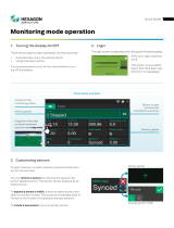
Monitoring Summary page

SP2+ Introduction Manual - updated firmware 5824
- 17 -
This is the Summary page with Sensor Status and the Event Log, with the Temperature Sensor
Graph enabled.
Host Log
The Host Log contains all entries from the “All Events” category. We’ll explain the different categories
in the Notifications manual.
The last 30 entries are shown, but if you’re scrolling down the list, more events (30 more) will be
loaded automatically. You can view the full log if you keep scrolling down.
In the Summary page’s Sensors Information window you can do the following:

SP2+ Introduction Manual - updated firmware 5824
- 18 -
Click on the configuration menu button directly next to the right of a sensor to access its popup
menu.
Directly acknowledge a sensor’s status, and put the sensor offline
Control the relay-type sensors
Enable/disable graph data collection per sensor (if they support it), and display the
graph display window for the Summary page
We’ll explain the Graph feature in more detail below.

SP2+ Introduction Manual - updated firmware 5824
- 19 -
Graph feature
After you’ve enabled the data collection for a sensor, you can choose to display specific time intervals
of the stored data: hourly/daily/weekly/monthly and custom display interval.
You can also export the recorded data in multiple formats.
Important: The maximum number of enabled graphs per unit is 14.
In this example picture, we’ve chosen to display the temperature sensor’s daily maximum.
You could also resize the graph window (including full screen) and move the scale to display more or
less data.
You can choose to export the graph data in selected
formats by clicking on the graph’s menu on the right,
then by choosing the desired format from the popup
menu.
The file will be downloaded automatically and
assigned a file name that will contain the sensor’s
name, IP address of the unit, and the date and time.

SP2+ Introduction Manual - updated firmware 5824
- 20 -
The graph is always a Live Graph; you can set the data collection period in the General Settings
page (see below for more information).
You may also refresh the graph data manually with the refresh button on the right.
If you want to view multiple sensor graphs, first you need to Enable Graph for a
sensor that supports graphing from the sensor’s menu. Then select View
Graph to display it. The data collection will run in the background even if you
don’t display the graph.
The second graph will appear below the first graph (you can freely rearrange it).
/