Entrematic Ditec EL34 User manual
- Category
- Motor vehicle electronics
- Type
- User manual
This manual is also suitable for

www.ditecentrematic.com
IP2152EN
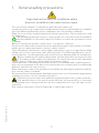
Ditec EL34
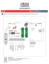
Control panel installation manual for QIK80EH barrier
(Original instructions)
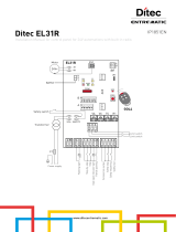
Safety reopening
Safety reopening
Automation status lamp
-
+
Output 24 V= / max 0,5 A
Power supply
BATKH
Flashing light
Lighting kit
Automatic closing
Opening
Closing
Stop
RDX
MD2
GOLR
POWER
ALARMSA11 IN12
VA VC TC R1 CB
AUX
24V~
012349 01G1 G3 0121 22018CNO
TRF
LN 14 0
PRG
COM
ENC
AUX
1
ON
2345
EL34
SIG
Transformer
24V=
Motor
BAT +G2-
1112 0
F1
F
U
S
E
BIXMR2
Limit switch
Limit switch
Safety switch
GOL4
+
M
-

20
IP2152EN - 2015-03-16
Index
Subject Page
1. General safety precautions 21
2. EC declaration of conformity 22
3. Technical specifications 22
3.1 Applications 22
4. Commands 23
5. Outputs and accessories 24
6. Settings 25
6.1 Trimmers 25
6.2 Dip-switches 26
6.3 Jumper 26
6.4 Signals 26
7. Radio 27
8. Start-up 28
9. Troubleshooting 29
10. Example of application for parallel automations 30
11. Example of application for automations with two-way interlocking device without pres-
ence detection
31
12. Example of application for automations with two-way interlocking device with presence
detection
32
13. Example of application for automations with two-way operating mode 33
Key
All the rights concerning this material are the exclusive property of Entrematic Group AB. Although the con-
tents of this publication have been drawn up with the greatest care, Entrematic Group AB cannot be held
responsible in any way for any damage caused by mistakes or omissions in this publication.
We reserve the right to make changes without prior notice. Copying, scanning and changing in any way are
expressly forbidden unless authorised in writing by Entrematic Group AB.
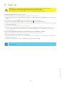
i
This symbol indicates useful information for the correct functioning of the product.
This symbol indicates instructions or notes regarding safety, to which special atten-
tion must be paid.

21
IP2152EN - 2015-03-16
This installation manual is intended for qualified personnel only.
Installation, electrical connections and adjustments must be performed in accordance
with Good Working Methods and in compliance with the present standards.
Read the instructions carefully before installing the product. Bad installation could
be dangerous.
The packaging materials (plastic, polystyrene, etc.) should not be discarded in
the environment or left within reach of children, as these are a potential source
of danger.
Before installing the product, make sure it is in perfect condition.
Do not install the product in explosive areas and atmospheres: the presence of inflam-
mable gas or fumes represents a serious safety hazard.
The safety devices (photocells, safety edges, emergency stops, etc.) must be installed
taking into account: applicable laws and directives, Good Working Methods, instal-
lation premises, system operating logic and the forces developed by the automation.
Before connecting the power supply, make sure the plate data correspond to that
of the mains power supply. An omnipolar disconnection switch with minimum
contact gaps of 3 mm must be included in the mains supply.
Check that there is an adequate residual current circuit breaker and a suitable overcur-
rent cut-out upstream of the electrical installation in accordance with Good Working
Methods and with the laws in force.
When requested, connect the automation to an effective earthing system that complies
with current safety standards.
During installation, maintenance and repair operations, cut off the power supply before
opening the cover to access the electrical parts.
The electronic parts must be handled using earthed antistatic conductive arms.
The manufacturer of the motorisation declines all responsibility in the event
of component parts being fitted that are not compatible with the safe and correct
operation.
Use original spare parts only for repairing or replacing products.
1. General safety precautions
“Important instructions for installation safety.
Incorrect installation can cause serious injury”

22
IP2152EN - 2015-03-16
The manufacturer Entrematic Group AB, with headquarters in Lodjursgatan 10, SE-261 44 Land-
skrona, Sweden,
declares that the Ditec EL34 type control panel complies with the conditions of the following
EC directives:
EMC Directive 2004/108/EC
Low Voltage Directive 2006/95/EC
R&TTE Directive 1999/5/EC
Landskrona, 14-02-2013 Marco Pietro Zini
(President EA)
2. EC Declaration of Conformity
3. Technical specifications
QIK80EH
Power supply 230 V~ 50/60 Hz
F1 fuse F2A
Motor output 24 V 16 A
Accessories power supply 24 V 0.5 A
Temperature
min -20° C max +55° C
min -35° C max +55° C with NIO ac-
tivated
min -10° C max +50° C with batteries
Degree of protection IP55
Radio frequency 433.92 MHz
Storable transmitters 200
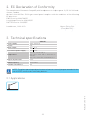
3.1 Applications
i
NOTE: The given operating and performance features can only be guaranteed with the
use of DITEC accessories and safety devices.

23
IP2152EN - 2015-03-16
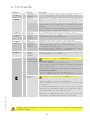
4. Commands
Command Function Description
1 2 N.O. AUTOMATIC
CLOSING
Permanently closing the contact enables automatic closing.
1 3 N.O. OPENING With DIP1=ON, closing the contact activates an opening opera-
tion.
STEP-BY-STEP With DIP1=OFF, closing the contact activates an opening or clos-
ing operation in the following sequence: opening-stop-closing-
opening.
N.B.: if automatic closing is enabled, the stop is not permanent
but has a duration set with the TC trimmer.
1 4 N.O. CLOSING The closing operation starts when the contact is closed.
1 8 N.C. REVERSAL
SAFETY
CONTACT
Opening the safety contact triggers a reversal of the movement
(reopening) during the closing operation.
1 9 N.C. STOP Opening the safety contact stops the current operation.
1 9 N.O. OPERATOR
PRESENT
CONTROL
Opening of contact 1-9 enables the operator present function.
- opening with operator present 1-3 [with DIP1=ON];
- closing with operator present 1-4.
N.B.: any safety devices, automatic closing and plug-in cards in
the AUX1, AUX2 and RDX housings are disabled.
1 G1 N.C. REVERSAL
SAFETY
CONTACT
Opening the safety contact triggers a reversal of the movement
(reopening) during the closing operation.
PRG
N.O. TRANSMITTER
STORAGE AND
CANCELLATION
WARNING: the storage module MUST BE inserted.
Transmitter storage:
- press the PRG key (the SIG LED turns on),
- proceed with transmission from the transmitter to be stored
(the SIG LED flashes),
- wait 10 s for storage to be completed (the SIG LED turns off).
Transmitter cancellation:
- press the PRG key for 3 s (the SIG LED flashes),
- press the PRG key again for 3 s (the SIG LED flashes faster).
SETTINGS
RESET WARNING: the storage module must NOT be inserted.
- press the PRG key for 4 s (the IN LED flashes),
- press the PRG key within 4 sec for another 2 sec (the IN LED
comes on).
The SETTINGS RESET deletes all the remote software settings
made using the MD2 display module. After SETTINGS RESET it
is possible to adjust the control panel directly.
WARNING: if the MD2 display module is disconnected from the
control panel, a SETTINGS RESET must be performed.
Warning: make a jumper for all NC contacts if not in use. The terminals with the same
number are equal.

24
IP2152EN - 2015-03-16
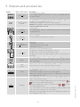
5. Outputs and accessories
Output Value - Accessories Description
0
-
1
+
24 V 0,5 A
Accessories power supply.
Power supply output for external accessories, including automa-
tion status lamps.
AUX1
AUX2
SOFA1-SOFA2
GOPAV
The control panel is fitted with two housings for plug-in cards such
as radio receivers, magnetic loops, etc.
Operating of the plug-in card is selected using DIP1.
WARNING: the plug-in cards must be inserted and removed with
the power supply disconnected.
014NOC
LAMPH
24 V 50 W
Flashing light.
The flashing light activates simultaneously with the opening and
closing operation.
014
QIKAFE
24 V 1 A
24V electric block.
It is activated when the barrier is closed.
+G2-
QIKLUX
24 V 300 mA max
Lighting kit.
On with barrier closed.
Flashing with barrier operating.
Off with barrier open
01G1 G3
24 V 3 W
Automation status light (proportional)
The light goes off when the automation is closed.
The light comes on when the automation is open.
The light flashes with a variable frequency while the automation is
operating.
ANT
BIXAL
If the GOLR radio receiver is used, connect the supplied antenna
wire (173 mm), or alternatively the BIXAL antenna, using a coaxial
cable, type RG58.
0121 22 MD2
DMCS
Allows connection of the MD2 display module for advanced control
of the functions or connection of the DMCS software.
RDX
GOLR
The control panel is fitted with a housing for a plug-in card such as
a GOLR radio receiver.
Operating of the plug-in card is selected using DIP1.
WARNING: the plug-in cards must be inserted and removed with the
power supply disconnected.
COM
BIXMR2
If the GOLR radio receiver is used, the storage module allows the
remote controls to be stored.
It allows the functioning configurations to be saved using the
function of the MD2 display module.
The saved configurations can be recalled via the function
of the MD2 display module.
If the control panel is replaced, the BIXMR2 storage module being
used can be inserted in the new control panel.
Warning: the storage module must be inserted and removed with the
power supply disconnected.

25
IP2152EN - 2015-03-16
Output Value - Accessories Description
BAT
BATKH
2x12 V 2Ah
Barrier operation.
The batteries are kept charged when the power supply is on. If the
power supply is off, the panel is powered by the batteries until the
power is re-establish or until the battery voltage drops below the
safety threshold. The panel turns off in the last case.
WARNING: the batteries must always be connected to the control
panel for charging. Periodically check the efficiency of the batteries.
N.B.: the operating temperature of the rechargeable batteries is
approximately +5°C/+40°C.
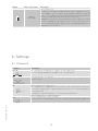
6. Settings
6.1 Trimmers
Trimmer Description
VA - VC
MAX
MIN
VA - Opening speed adjustment. Adjusts the opening speed.
VC - Closing speed adjustment. Adjusts the closing speed.
TC
MIN=0 s
60 s10 s
MAX=120 s
Setting automatic closing time.
From 0 to 120 s.
R1
MAX
MIN
Thrust adjustment on obstacles.
The control panel is equipped with a safety device that stops motion if an obstacle
is encountered during the opening operation and reverses motion during the
closing operation.
R1=MIN gives maximum obstacle sensitivity (minimum thrust).
With R1=MAX, there is maximum thrust.
CB
MAX
MIN
Deceleration distance when closing.
Controls the deceleration distance when closing to allow an optimum approach.

26
IP2152EN - 2015-03-16
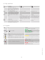
6.2 Dip-switches
DIP Description OFF ON
DIP1 Command functions 1-3.
N.B.: also sets operating of the
plug-in cards connected on
AUX1, AUX2 and RDX.
Step-by-step. Opening.
DIP2 Selecting opening direction.
The opening direction is intend-
ed by viewing the automation
from the side being examined.
Opening to the right. Opening to the left.
DIP3 Opening with safety devices
open.
Enabled.
The opening of contacts 1-8
with the automation idle allows
immediate opening by means of
command 1-3 or remote control.
Disabled.
The opening of contact 1-8
with the automation idle
prevents all operations.
DIP4 FUTURE USE / /
DIP5 Electronic antifreeze system.
Maintains motor efficiency even
at low ambient temperatures.
Enabled. Disabled.
6.3 Signals
LED On Flashing
POWER 24V power supply.
Encoder not working.
Current overload on
flashing light output.
Shortcircuiting of
flashing light driver.
SA Indicates that at least one of the safety contacts
is open. /
IN Activated at every command and adjustment to
the dip-switch. SETTINGS RESET in progress.
11 Indicates that the 0-11 limit switch contact is open. /
12 Indicates that the 0-12 limit switch contact is open. /
SIG Transmitter enabling/storage phase.
Radio transmission of a stored remote
control received.
Radio transmission of an unstored
remote control received.
Transmitters being can-
celled.
Damaged storage.

27
IP2152EN - 2015-03-16
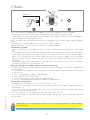
The control panel is equipped with a radio receiver with a frequency of 433.92 MHz.
The antenna consists of a rigid wire, 173 mm long, connected to the ANT clamp.
It is possible to increase the range of the radio by connecting the antenna of the flashing lights,
or by installing the tuned BIXAL antenna.
N.B.: To connect the external antenna to the control panel, use a coaxial cable, type RG58 (max.
10 m).
Check that the storage module is inserted in the COM connector.
Up to 200 remote controls can be stored in the storage module.
Transmitter storage:
- Press the PRG key on the radio receiver or on the control panel; the SIG indicator LED lights
up;
- Proceed with transmission by pressing the CH keys on the remote control that you want to
store (within the range of the radio receiver). The remote control is now stored. During this
phase, the SIG indicator LED flashes. When the SIG LED comes on again, you can validate
another remote control. Validate all the new remote controls by making a transmission as
indicated;
- You automatically exit the procedure 10 seconds after the last transmission, or you can press
the PRG key again (the SIG LED goes off).
Up to four CH keys of a single remote control can be stored:
- If only one (any) CH key of the remote control is stored, command 1-3 (step-by-step/opening)
is carried out;
- If 2-4 CH keys of a single remote control are stored, the functions matched with the CH keys
are as follows:
• CH1=command1-3step-by-step/opening;
• CH2=NOSETTINGSELECTED;
• CH3=commandtoswitchon/offthecourtesylight;
• CH4=stopcommand,equivalenttoimpulsivecommand1-9.
Transmitter cancellation:
- Hold down the PRG key for 3 s; the SIG LED starts to flash;
- To cancel all the remote controls from the memory, press the PRG key again, keeping it
pressed for 3 s;
- To cancel a single remote control, press any one of the previously memorised CH keys of the
remote control to be cancelled;
- The cancellation is confirmed by the quick flashing of the SIG LED.
If the control panel is replaced, the storage module being used can be inserted in the new
control panel.
10 s
CH1 CH2
CH3 CH4
1 2 3
PRG
Receiver
7. Radio
WARNING: the storage module must be inserted and removed with the power supply
disconnected.
i
For further information see the user manual for GOL series remote controls.

28
IP2152EN - 2015-03-16
WARNING: The operations in point 5 are performed without safety devices.
The trimmers can only be adjusted with the automation idle.
The automation automatically slows when approaching the stops.
8. Start-up
•Make a jumper for NC safety contacts.
•Move the bar into the opening and closing position by hand.
Adjust the mechanical stops and limit switches as indicated in the QIK80EH barrier installation
manual.
•Set the correct opening direction with DIP2, as shown on page 26.
•Connect the power supply cable to terminals L-N- as shown on page 19.
•Switch on and check the automation is operating correctly with the subsequent opening and
closing commands.
•Check that the limit switches are activated.
•Connect the safety devices (removing the relative jumpers) and check they function cor-
rectly. If required, activate automatic closing with command 1-2 and adjust the time with
the TC trimmer.
•Set the desired opening and closing speeds with the VA and VC trimmers.
•Adjust the deceleration distance when closing with the CB trimmer.
•Set the obstacle thrust with the R1 trimmer.
Warning: Ensure that the forces exerted by the door wings are compliant with EN12453-
EN12445 regulations.
•Connect any other accessories and check they are functioning.
N.B.: in the event of servicing or if the control panel is to be replaced, repeat the start-
up procedure.
i

29
IP2152EN - 2015-03-16
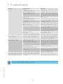
9. Troubleshooting
Problem Possible causes Operation
The automation does not open
or close.
No power.
(POWER ALARM LED off).
Check that the control panel is pow-
ered correctly.
Short circuited accessories.
(POWER ALARM LED off).
Disconnect all accessories from ter-
minals 0-1 (a voltage of 24V= must be
present) and reconnect them one at a
time.
Blown line fuse.
(POWER ALARM LED off).
Replace fuse F1.
Safety contacts are open.
(SA LED on).
Check that the safety contacts are
closed correctly (NC).
SAFETY SWITCH release microswitch
open.
(LEDs 11 and 12 on).
Check that the hatch is closed correctly
and the microswitch makes contact.
The remote control does not work. Check that the radio receiver and stor-
age module are present.
Check that the transmitters have been
correctly stored on the radio.
Photocells activated.
(SA LED on).
Check that the photocells are clean
and operating correctly.
The automatic closing does not work. Check that contact 1-2 is closed.
The external safety devices
are not activated.
Incorrect connections between the
photocells and the control panel.
Connect NC safety contacts together in
series and remove any jumpers on the
control panel terminal board.
The automation opens/closes
briefly and then stops.
Encoder disconnected, false encoder
contacts, encoder fault.
(flashing POWER ALARM LED).
Check that the encoder is connected
correctly, clean the contacts by con-
necting and disconnecting the en-
coder plug on the contacts, replace
encoder.
Motor leads crossed.
(flashing POWER ALARM LED).
Check the motor leads.
There is friction or the spring tension
is not correct.
Manually check that the automation
moves freely and check the R1 adjust-
ment. Check spring tension.
The remote control has lim-
ited range and does not work
with the automation moving.
The radio transmission is impeded by
metal structures and reinforced con-
crete walls.
Install the antenna outside.
Substitute the transmitter batteries.
N.B.: if the MD2 display module is present, consult the Alarm and fault visualisation
chapter in the relevant installation manual.
i

30
IP2152EN - 2015-03-16
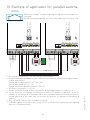
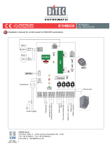
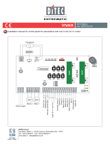
1- Disconnect connectors 0-1-G1-G3 from the control panels.
2- Using the MD2 display modules connected to the control panels, set the following parameters
on both automations:
Setting advanced parameters AP > AA > ON
Setting input mode AP > G1 > SY
Setting automation parallel mode AP > PA > 01
3- Reconnect connectors 0-1-G1-G3.
4- Enable automatic closing on both automations by making a jumper for contacts 1-2.
5- Set the automatic closing time of automation A with the TC trimmer as desired, set the TC
trimmer of automation B to maximum. (With this setting the automations will perform the
closing operation at the same time as the time set with the TC trimmer of automation A
expires).
6- Only one GOLR radio receiver should be installed.
7- If QIKLUX lighting kits are present, set AP>G2=03 or AP>G2=02 to synchronise the lighting
with the closed automations.
10. Example of application for parallel automa-
tions
MD2
AB
01234901G1 G3 0121 22018
MD2
01234901G1 G3 0121 22018
Safety reopening
Stop
Closing
Opening
Automatic closing
Stop
Automatic closing
VA VC TC R1 CB VA VC TC R1 CB
GOLR
1
ON
2345 1
ON
2345
1112 0
Limit switch
Limit switch
Safety switch
1112 0
Limit switch
Limit switch
Safety switch
With these settings, an obstacle during closing will cause both barriers
to reopen.
An obstacle during opening will cause only the barrier involved to stop.

31
IP2152EN - 2015-03-16
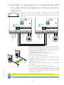
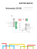
11. Example of application for automations with
two-way interlocking device without presence
detection
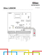
1- Disconnect connectors 0-1-G1-G3 from the control panels.
2- Using the MD2 display modules connected to the control
panels, set the following parameters on both automations:
Setting advanced parameters AP > AA > ON
Setting input mode AP > G1 > SY
Setting automation parallel mode AP > PA > 02
3- Reconnect connectors 0-1-G1-G3.
4- Set DIP1=ON on both automations.
5- The radio controls will have to be handled as opening
commands 1-3 (RO>C1>1-3)
6- Enable automatic closing on both automations by making
a jumper for contacts 1-2.
7- Adjust the automatic closing time with the TC trimmer
as required.
8- Set the opening delay time (from 0 to 30 s).
9- The reservation function (PG) can be enabled if a vehicle
arrives in the same direction while another one is still
between the barriers BC>PG>ON. A second opening
command is stored and executed as soon as the cycle
in progress terminates.
MD2
AB
01234 9 01G1 G3 0121 22018
MD2
01234901G1 G3 0121 22018
Stop
Opening
Automatic closing
Safety reopening
Safety reopening
Opening
Automatic closing
Stop
VA VC TC R1 CB VA VC TC R1 CB
1
ON
2345 1
ON
2345
1112 0
Limit switch
Limit switch
Safety switch
1112 0
Limit switch
Limit switch
Safety switch
DIP1=ON DIP1=ON
WARNING: the opening commands are disabled during the interlocking cycle
In the event of an emergency, the operator present commands can be used (contact 1-9).
With these connections and settings, command 1-3 starts an opening
operation of barrier A (or B) which closes after the time set with TC.
When time TO elapses, barrier B will open and will close after the time
set with TC.
A
B
i

32
IP2152EN - 2015-03-16
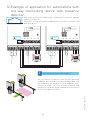
You can connect two barriers with one-way operating
mode with presence detection by installing a detection
device between the two barriers (e.g. magnetic loop).
Connect terminals 1-2 of the entrance A barrier and
automatic closing will only be enabled when the vehicle
activates the detection device.
12. Example of application for automations with
one-way interlocking device with presence
detection
MD2
AB
01234 9 01G1 G3 0121 22018
MD2
01234901G1 G3 0121 22018
Stop
Opening
Automatic closing
Safety reopening
Safety reopening
Opening
Automatic closing
Stop
VA VC TC R1 CB VA VC TC R1 CB
1
ON
2345 1
ON
2345
1112 0
Limit switch
Limit switch
Safety switch
1112 0
Limit switch
Limit switch
Safety switch
DIP1=ON DIP1=ON
For the connections, refer to par. 11.
With these connections and settings, command 1-3 starts an opening
operation of barriers.
Automatic closing will only be enabled when the vehicle activates the
detection device.
A
B
i

33
IP2152EN - 2015-03-16
13. Example of application for automations with
two-way operating mode with vehicle direc-
tion detection.
In the event of access to car park after paying and free exit:
1- Using the MD2 display module, set the following parameters:
BA>AN>3A
AP>D8>LO with this setting, command 1-8 performs a stop and not a reversal.
BA>TO>.. set the delay time during opening of command 1-G1.
BA>TS>.. set the automatic closing time restore time after release of command 1-8.
2- Connect the outer side opening command (e.g. LAN60) to terminals 1-3.
3- Connect the safety device to terminals 1-8.
4- Insert the LAB9 card on AUX1.
5- Enable automatic closing with jumper 1-2.
6- Adjust the TC trimmer.
7- Set DIP1=ON
8- Set the delay time TO.
9- Immediate reclosing of the barrier is possible (BA>TS>00).
Exiting vehicles open the barrier with the AUX1 command.
We recommend setting AP>D8>LO to prevent unauthorised access.
MD2
01234901G1 G3 0121 22018
Opening
Opening
Automatic closing
Safety reopening
VA VC TC R1 CB
1
ON
2345
DIP1=ON
With these settings, the control panel recognises vehicles as they enter and disa-
bles the AUX1 command for the set period TO; The counter starts when command
1-8 is released, after command 1-3 is given.

IP2152EN - 2015-03-16
Entrematic Group AB
Lodjursgatan 10
SE-261 44, Landskrona
Sweden
www.ditecentrematic.com
-
 1
1
-
 2
2
-
 3
3
-
 4
4
-
 5
5
-
 6
6
-
 7
7
-
 8
8
-
 9
9
-
 10
10
-
 11
11
-
 12
12
-
 13
13
-
 14
14
-
 15
15
-
 16
16


Entrematic Ditec EL34 User manual
- Category
- Motor vehicle electronics
- Type
- User manual
- This manual is also suitable for
Ask a question and I''ll find the answer in the document
Finding information in a document is now easier with AI
Related papers
-
 DITEC Ditec E1A User manual
-
Entrematic Ditec EL31R Installation guide
-
 DITEC GLOBE Owner's manual
-
-
-
DITEC Ditec CROSS - IP1747 Owner's manual
-
-
DITEC Ditec NES400EH Owner's manual


Other documents
-
 DITEC GOL4-C Programming Manual
-
 Entre Matic Ditec EL31R User manual
-
 DITEC EL31R Owner's manual
-
 DITEC E1HBOX Owner's manual
-
HySecurity Nice Signo Owner's manual
-
 DITEC E2 Owner's manual
-
 DITEC LOGICM Owner's manual
-
 DITEC E1T Owner's manual
-
 DITEC VIVAH Owner's manual
-
 Ditec Entrematic CS12E User & Installation Manual


