Page is loading ...

Electronic controllers for refrigeration units
ID
PLUS
902/961/971/974
EN

CONTENTS EN
IDPLUS 902/961 USER INTERFACE (KEYS AND LEDS) .......................................................................................... 4
IDPLUS 971/974 USER INTERFACE (KEYS AND LEDS) .......................................................................................... 6
IDPLUS 902/961 CONNECTIONS .............................................................................................................................. 8
IDPLUS 902/961 APPLICATIONS ............................................................................................................................... 9
IDPLUS 971 CONNECTIONS ...................................................................................................................................... 10
IDPLUS 971 APPLICATIONS ........................................................................................................................................ 11
IDPLUS 974 CONNECTIONS ...................................................................................................................................... 12
IDPLUS 974 APPLICATIONS ........................................................................................................................................ 13
LOADING DEFAULT APPLICATIONS ........................................................................................................................ 14
SETPOINT MODIFICATION LOCK ............................................................................................................................. 14
INSTRUMENT ON/OFF ................................................................................................................................................ 14
ACCESSING AND USING THE MENUS ..................................................................................................................... 14
MANUAL DEFROST CYCLE ACTIVATION ................................................................................................................ 15
MECHANICAL INSTALLATION - DIMENSIONS ....................................................................................................... 15
TROUBLESHOOTING ................................................................................................................................................... 15
ALARMS .......................................................................................................................................................................... 16
PASSWORDS ................................................................................................................................................................. 18
USING THE COPYCARD .............................................................................................................................................. 18
MACHINE STATUS MENU ........................................................................................................................................... 19
PROGRAMMING MENU ............................................................................................................................................... 19
MAX/MIN TEMPERATURE ALARMS........................................................................................................................... 20
LIABILITY AND RESIDUAL RISKS ................................................................................................................................ 20
DISCLAIMER ................................................................................................................................................................... 21
ELECTRICAL CONNECTIONS ..................................................................................................................................... 21
CONDITIONS OF USE ................................................................................................................................................. 21
TECHNICAL DATA (EN 60730-2-9) ............................................................................................................................ 22

FURTHER INFORMATION (INPUT, OUTPUT AND MECHANICAL FEATURES - APPLICABLE REGULATIONS) 22
DESCRIPTION OF IDPLUS 902/961 FAMILY ............................................................................................................ 24
TABLE OF USER MENU PARAMETERS (IDPLUS 902/961) ..................................................................................... 25
TABLE OF INSTALLER MENU PARAMETERS (IDPLUS 902/961) .......................................................................... 26
DESCRIPTION OF IDPLUS 971 FAMILY .................................................................................................................... 30
TABLE OF USER MENU PARAMETERS (IDPLUS 971) ............................................................................................. 31
TABLE OF INSTALLER MENU PARAMETERS (IDPLUS 971) ................................................................................... 32
DESCRIPTION OF IDPLUS 974 FAMILY .................................................................................................................... 37
TABLE OF USER MENU PARAMETERS (IDPLUS 974) ............................................................................................. 38
TABLE OF INSTALLER MENU PARAMETERS (IDPLUS 974) ................................................................................... 39

STANDBY (ESC)
Press and release
Returns to the previous menu level
Confirms parameter value
Press for at least 5 sec
Activates the Standby function
(when outside the menus)
UP
Press and release
Scroll menu items
Increases values
Press for at least 5 sec
Activates the Manual Defrost function
DOWN
Press and release
Scroll menu items
Decrease values
Press for at least 5 sec
Function can be configured by the user
(par. H32)
SET (ENTER)
Press and release
Displays alarms (if active)
Opens Machine Status menu
Press for at least 5 sec
Opens Programming menu
Confirm commands
KEYS
set
IDPlus 902/961 USER INTERFACE
ID
PLUS
902/961

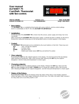
* When switched on, the device performs a Lamp Test; the display and LEDs will flash for several
seconds to check that they all function correctly.
* To activate the LOC function: - enter the “Basic Commands” menu by pressing the key set .
- press keys and within 2 seconds.
If the LOC function is Active and you try to enter the “Programming” menu, the text LOC
appears. If this happens, the parameters are still displayed but cannot be edited.
To disable the keypad lock, repeat the aforementioned procedure.
Reduced SET / Economy LED
Flashing: economy Setpoint active
Quick flashing: access to level2 parameters
Off: otherwise
Compressor LED
Permanently on: compressor active
Flashing: a delay, a protection or a
locked start-up
Off: otherwise
Defrost LED
Permanently on: defrost active
Flashing: manual or D.I. activation
Off: otherwise
Alarm LED
Permanently on: alarm active
Flashing: alarm acknowledged
Off: otherwise
HEAT status LED
Permanently on: compressor in HEAT
Off: otherwise
NOT USED
°C LED
Permanently on: °C setting (dro = 0)
Off: otherwise
°F LED
Permanently on: °F setting (dro = 1)
Off: otherwise
LEDs

Standby (ESC)
Press and release
Returns to the previous menu level
Confirms parameter value
Press for at least 5 sec
Activates the Standby function
(when outside the menus)
UP
Press and release
Scroll menu items
Increases values
Press for at least 5 sec
Activates the Manual Defrost function
DOWN
Press and release
Scroll menu items
Decrease values
Press for at least 5 sec
Function can be configured by the user
(par.H32)
SET (ENTER)
Press and release
Displays alarms (if active)
Opens Machine Status menu
Press for at least 5 sec
Opens Programming menu
Confirm commands
KEYS
set
ID
PLUS
971/974
IDPlus 971/974 USER INTERFACE

Reduced SET / Economy LED
Flashing: economy Setpoint active
Quick flashing: access to level2 parameters
Off: otherwise
Compressor LED
Permanently on: compressor active
Flashing: a delay, a protection or a
locked start-up
Off: otherwise
Alarm LED
Permanently on: alarm active
Flashing: alarm acknowledged
Off: otherwise
°C LED
Permanently on: °C setting (dro =0)
Off: otherwise
°F LED
Permanently on: °F setting (dro =1)
Off: otherwise
LEDs
Defrost LED
Permanently on: defrost active
Flashing: manual or D.I. activation
Off: otherwise
Fans LED
Permanently on: fans active
Off: otherwise
Aux LED
Permanently on: Aux output active
Flashing: manual or D.I. activation of
Deep Cooling
* When switched on, the device performs a Lamp Test; the display and LEDs will flash for several
seconds to check that they all function correctly.
* To activate the LOC function: - enter the “Basic Commands” menu by pressing the key set .
- press keys and within 2 seconds.
If the LOC function is Active and you try to enter the “Programming” menu, the text LOC
appears. If this happens, the parameters are still displayed but cannot be edited.
To disable the keypad lock, repeat the aforementioned procedure.

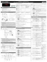
IDPLUS 902/961 CONNECTIONS
IDPlus 902: TERMINALS IDPlus 961: TERMINALS
OUT1 OUT1 relay 2-3-4: 12Va or 5-6-7: 230Va1-2: Compressor relay
Supply 6-7: models 12Va or 3-4: models 230VaSupply 6-7: models 12Va or 3-4: models 230Va
N-L 230Va power supply N-L 230Va power supply
10-9 Probe Pb1 10-9 Probe Pb1
10-11 Digital Input 1/ Pb3 probe 10-11 Digital Input 1/ Pb3 probe
TTL TTL Input TTL TTL Input
version with Pb3
(H11=0 and H43=y)
version with D.I.1
(H11≠0 and H43=n)
Pb3
910
Pb1
11
8
D.I.1
910
Pb1
11
8
Probe
connections
MODELS 12V~/c
2 3
4
5
6 7
ID
PLUS
902
Load
N
L
8 9 10 11
TTL
Power
Supply
MODELS 12V~/c
I
D
PLUS
961
126 7
N
L
8 9 10 11
TTL
Power
Supply
MODELS 230V~
I
D
PLUS
961
N
L
123 4
8 9 10 11
TTL
Power
Supply
MODELS 230V~
3
4
5
6 7
I
D
PLUS
902
Load
N
L
8 9 10 11
TTL
Power
Supply

F = Functions
H = Inputs and Outputs
R = Relay Output
APP.
1
APP.
2
APP.
3
APP.
4
Cold application X X X
Hot application X
F - Timed defrost X X
F - Alarm on Pb1 X X X X
F - Overheating X
H - Pb1 present X X X X
H - Pb3 / D.I.1 enabled D.I. D.I. Pb3
R - Compressor/Filling X X X
R - Heating elements X
Pb1
Ambient
Resistor
Pb1
Ambient
Evaporator
T.E.V.
Compressor
Pb3
Application settings Application 1&2
Application 3
Application 4
Pb1
Ambient
Evaporator
T.E.V.
Compressor
D.I.1
1€
1€
Valve
Ambient = Ambient Valve = Valve
Evaporator = Evaporator Compressor = Compressor
Resistor = Resistor T.E.V. = Thermostatic Expansion Valve

IDPLUS 971 CONNECTIONS
IDPlus 971: TERMINALS
1-2: Compressor relay TTL TTL Input or Digital Input 2
Defrost relay 2-3-4: 12Va or 5-6-7: 230Va10-9 Probe Pb1
Supply 6-7: models 12Va or 3-4: models 230Va10-8 Probe Pb2
N-L 230Va power supply 10-11 Digital Input 1/ Pb3 probe
F = Functions
H = Inputs and Outputs
R = Relay Output
APP.
1
APP.
2
APP.
3
APP.
4
Cold application X X X X
F - End defrost by time X X
F - End defrost by temperature X X
F - Alarm on Pb1 X X X X
F - Compressor OFF X
H - Pb1 present X X X X
H - Pb2 present X X
H - Pb3 / D.I.1 enabled D.I. D.I. D.I. D.I.
H - Buzzer X
R - Compressor X X X X
R - Heating elements X X
R - Fans X
R - Alarm X
Application settings
version with Pb3
(H11=0 and H43=y)
version with D.I.1
(H11≠0 and H43=n)
Pb3
910
Pb1
11
8
Pb2
D.I.1
910
Pb1
11
8
Pb2
Probe
connections
I
D
PLUS
971
12345 6 7
8 9 10 11
N
L
TTL
D.I.2
MODELS 12V~/c
max. 17A
Power
Supply
MODELS 230V~
I
D
PLUS
971
12345 6 7
8 9 10 11
N
L
TTL
D.I.2
Power
Supply

Application 3
Application 1 Application 2
Application 4
Evaporator
T.E.V.
Pb1
Ambient
Valve
D.I.1
1€
1€
Compressor
Pb2
Evaporator
T.E.V.
Pb1
Ambient
Valve
D.I.1
1€
1€
Compressor
Evaporator
T.E.V.
Pb1
Ambient
Valve
D.I.1
Compressor
Pb2
Evaporator
T.E.V.
Pb1
Ambient
Valve
D.I.1
1€
1€
Compressor
External Alarm
Internal
Buzzer
Ambient = Ambient Valve = Valve
Evaporator = Evaporator Compressor = Compressor
Internal Buzzer = Internal Buzzer T.E.V. = Thermostatic Expansion Valve
External Alarm = External Alarm

IDPLUS 974 CONNECTIONS
IDPlus 974: TERMINALS
0-2: Fans relay 10-9 probe Pb1
1-2: Compressor relay 10-8 probe Pb2
Defrost relay 2-3-4: 12Va or 5-6-7: 230Va10-11 Digital Input 1/ Pb3 probe
Supply 6-7: models 12Va or 3-4: models 230VaTTL TTL Input or Digital Input 2
N-L 230Va power supply
F = Functions
H = Inputs and Outputs
R = Relay Output
APP.
1
APP.
2
APP.
3
APP.
4
Cold application XXXX
F - End defrost by temperature XXXX
F - HACCP X
F - Alarm on Pb1 XXXX
H - Pb1 present XXXX
H - Pb2 present XXXX
H - Pb3 / D.I.1 enabled D.I. Pb3 D.I. D.I.
H - Buzzer XXXX
R - Compressor XXXX
R - Heating elements X X
R - Fans XXXX
R - Auxiliary X
R - Reversing valve X
Application settings
version with Pb3
(H11=0 and H43=y)
version with D.I.1
(H11≠0 and H43=n)
Pb3
910
Pb1
11
8
Pb2
D.I.1
910
Pb1
11
8
Pb2
Probe
connections
I
D
PLUS
974
12345 6 7
8 9 10 11
N
L
TTL
0
D.I.2
MODELS 12V~/c
max. 17A
Power
Supply
I
D
PLUS
974
12345 6 7
8 9 10 11
N
L
TTL
0
D.I.2
MODELS 230V~
max. 17A
Power
Supply

Application 3
Application 1 Application 2
Application 4
Ambient = Ambient Valve = Valve
Evaporator = Evaporator T.E.V. = Thermostatic Expansion Valve
Compressor = Compressor AUX = AUX
Reversing valve = Reversing valve Internal Buzzer = Internal Buzzer
Internal
Buzzer
Evaporator
T.E.V.
Pb1
Ambient
Valve
D.I.1
Compressor
Pb2
Internal
Buzzer
Evaporator
T.E.V.
Pb1
Ambient
Valve
D.I.1
1€
1€
Compressor
Pb2
Internal
Buzzer
Evaporator
T.E.V.
Pb1
Pb3
Ambient
HACCP
Valve Compressor
Pb2
Internal
Buzzer
Evaporator
T.E.V.
Pb1
Ambient
D.I.1
Compressor
Pb2
1€
1€
Reversing
Valve

The keypad can be locked by entering the “Basic Commands” menu using set and pressing and
within 2 seconds, or by programming the “LOC” parameter (see “diS” folder). If the keypad is locked, the “Basic
Commands” menu can be accessed and the Setpoint displayed, but the value cannot be modified.
LOADING DEFAULT APPLICATIONS
The procedure used to load one of the default applications is:
• when the instrument switches on, press and hold the set key: the label “AP1” will appear;
• scroll through the various applications (AP1-AP2-AP3-AP4) using the and keys;
• select the desired application using the key set (“AP3” in the example) or cancel the procedure by
pressing the key ; alternatively wait for the timeout;
• if the operation is successful, the display will show “y”, otherwise “n” will appear;
• after a few seconds the instrument will return to the main display.
set
Power-on + set
ACCESSING AND USING THE MENUS
Resources are organised into menus. Press and release the set key to access the “Machine Status” menu.
To access the “Programming” menu, press the set key for more than 5 seconds. If no keys are pressed for over 15
seconds (Timeout), or if the key is pressed, the last value to appear on the display is confirmed.
LOCK SETPOINT MODIFICATION
The instrument can be switched off by pressing the key for longer than 5 seconds. In this condition, the
adjustment algorithms and defrost cycles are disabled and the text “OFF” will appear on the display.
INSTRUMENT ON/OFF

MOUNTING - DIMENSIONS
74mm
32mm
29mm
71mm
70mm
67mm
The device is designed for panel mounting. Drill a 29x71 mm hole and insert the instrument; secure it with the
special brackets provided. Do not install the instrument in damp and/or dirty places; in fact, it is suitable for use
in places with ordinary or normal levels of pollution.
Keep the area around the instrument cooling slots adequately ventilated.
Alarms are always indicated by the buzzer (if present) and the alarm icon .
To switch off the buzzer, press and release any key; the corresponding icon will continue to flash.
N.B.: If alarm exclusion times have been set (see “AL” folder) the alarm will not be signalled.
In the event of an alarm caused by a malfunctioning ambient probe (Pb1), the indication “E1” will appear on the
display. For a malfunctioning evaporator probe (Pb2), the indication “E2” will appear (IDPlus 971/974 only).
Finally, for a malfunctioning Pb3 probe, the indication “E3” will appear on the display.
DIAGNOSTICS
Hold down the key for longer than 5 seconds. It is only activates if the temperature conditions are fulfilled.
Otherwise, the display will flash three times to indicate that the operation will not be performed.
MANUAL DEFROST CYCLE ACTIVATION

ALARMS
Label Fault Cause Effects Remedy
E1 Cold room
probe1 faulty
• measured values are outside operating
range
• Probe faulty/short-circuited/open
• Display label E1
• Alarm icon permanently on
• Disable max/min alarm controller
• Compressor operation based on parameters
“Ont” and “OFt”.
• check probe type (par. H00)
• check probe wiring
• replace probe
E2
Defrost probe2
faulty
only on IDPlus
971/974
• measured values are outside operating
range
• probe faulty/short-circuited/open
• Display label E2
• Alarm icon permanently on
• The Defrost will end due to Timeout (dEt)
• The evaporator fans will be: on if the
compressor is ON, or running in accordance with
the FCO parameter if the compressor is OFF
• check probe type (par. H00)
• check probe wiring
• replace probe
E3 Probe3 faulty
• measured values are outside operating
range
• probe faulty/short-circuited/open
• Display label E3
• Alarm icon permanently on
• check probe type (par. H00)
• check probe wiring
• replace probe
AH1 Alarm for HIGH
Pb1 temperature
value read by Pb1 > HAL after time of
“tAO” (see “MAX/MIN TEMP. ALARMS)
• Recording of label AH1 in folder AL
• No effect on regulation
Wait until value read by Pb1 returns
below HAL
AL1 Alarm for LOW
Pb1 temperature
value read by Pb1 < LAL after time of
“tAO” (see “MAX/MIN TEMP. ALARMS)
• Recording of label AL1 in folder AL
• No effect on regulation
Wait until value read by Pb1 returns
above LAL
EA External alarm Digital input activated
(H11 = ±5)
• Recording of label EA in folder AL
• Alarm icon permanently on
• Regulation locked if rLO = y
check and remove the external cause
which triggered the alarm on the D.I.
OPd Door open alarm
digital input activation
(H11 = ±4)
(for longer than tdO)
• Recording of label Opd in folder AL
• Alarm icon permanently on
• Controller locked
• close the door
• delay function defined by OAO
Ad2 Defrost due to
timeout
end of defrost cycle due to timeout rather
than due to defrost end temperature being
recorded by Pb2
• Recording of label Ad2 in folder AL
• Alarm icon permanently on
wait for the next defrost cycle for
automatic return

Label Fault Cause Effects Remedy
COH Over Heating
alarm Pb3 value set by parameter SA3 exceeded
• Recording of label COH in folder AL
• Alarm icon permanently on
• Regulation locked (Compressor)
• wait for the temperature to return
to a value of SA3 (Setpoint) minus
dA3 (differential)
nPA General pressure
switch alarm
Activation of pressure alarm by general
pressure switch
If the number N of pressure switch activations is:
N < PEn:
• Recording of folder nPA in folder AL, with the
number of pressure switch activations
• Regulation locked (Compressor and Fans)
• check and remove the cause which
triggered the alarm on the D.I.
(Automatic Reset)
PAL General pressure
switch alarm
Activation of pressure alarm by general
pressure switch
If the number N of pressure switch activations is:
N = PEn:
• Display label PAL
• Recording of label PA in folder AL
• Alarm LED steady
• Regulation locked (Compressor and Fans)
• Switch the device off and back
on again
• Reset alarms by entering the
functions folder and selecting the
rAP function (Manual Reset)
HC n
Max/Min Pb3
value when out
of range (SLH...
SHH)
Logs the Max/Min value recorded by Pb3
when it exceeds range SLH...SHH.
“n” represents the sequential number of
times the range is exceeded.
• Recording of folder “HC n” in folder AL
• Alarm LED steady
• No effect on regulation
NB: “n” can assume the values 1 to 8.
If n > 8, folder HC8 will flash and the
system will overwrite folders where n=1
tC n
Pb3 out-of-range
dwell time
(SLH...SHH)
Stores the dwell time of the Pb3 value outside
range SLH...SHH. n” represents the sequential
number of times the range is exceeded.
• Recording of folder “tC n” in folder AL
• Alarm LED steady
• No effect on regulation
NB: “n” can assume the values 1 to 8.
If n > 8, folder HC8 will flash and the
system will overwrite folders where n=1
bC n
Value recorded
by Pb3 on return
from bOt
Logs the value recorded by Pb3 on return
from a blackout. “n” represents the sequential
number of blackouts that have occurred.
• Recording of folder “bC n” in folder AL
• No effect on regulation
NB: “n” can assume the values 1 to 8.
If n > 8, folder bC8 will flash and the
system will overwrite folders where n=1
bt n
Pb3 out-of-range
dwell time
during bOt
Stores the out-of-range dwell time of the
Pb3 value during a blackout.
“n” represents the sequential number of
blackouts that have occurred.
• Recording of folder “bt n” in folder AL.
The value contained will be 0 if the value of
Pb3 has remained within the range, ≠ 0 if the
value has gone outside of the range
• No effect on regulation
N.B.: “n” can assume the values
1 to 8.
If n > 8, folder bC8 will flash and
the system will overwrite folders
where n=1
NOTE: to delete folders “HC n”, “tC n”, “bC n” and “bt n” from folder AL, start function rES in folder FnC.

Password “PA1”: used to access User parameters. The password is not enabled by default (PS1=0).
To enable it (PS1≠0): press and hold set for longer than 5 seconds, scroll through the parameters using and
until you see the label PS1, press set to display the value, modify it using and , then save it by pressing
set or . If enabled, it will be required in order to access the User parameters.
Password “PA2”: used to access Installer parameters. The password is enabled by default (PS2=15).
To modify it (PS2≠15): press set and hold for longer than 5 seconds, scroll through the parameters using and
until you see the label PA2, press set , set the value to “15” using and , then confirm using set .
Scroll through the folders until you find the label diS and press set to enter. Scroll through the parameters using
and until you see the label PS2, press set to display the value, modify it using and , then save it by
pressing set or . The visibility of “PA2” is as follows:
1) PA1 and PA2 ≠ 0: Press and hold set for longer than 5 seconds to display “PA1” and “PA2”. It will then be
possible to decide whether to access the User (PA1) or the Installer (PA2) parameters.
2) Otherwise: The password “PA2” is amongst the level1 parameters. If enabled, it will be required when
accessing the Installer parameters; to enter it, proceed as instructed for password “PA1”.
If the password entered is incorrect, the label PA1/PA2 will be displayed again and the procedure will need to be
repeated.
PASSWORD
The Copy Card is connected to the serial port (TTL) and allows rapid programming of the instrument parameters.
Access Installer parameters by entering “PA2”, scroll through the folders using and until folder FPr appears.
Select it using set , scroll through the parameters using and , then select the function using set (e.g. UL).
• Upload (UL): Select UL and press set . This function uploads the programming parameters from the instrument to
the card. If the procedure is a success, “y”, will appear on the display, otherwise “n” will appear.
• Format (Fr): This command is used to format the copy card, (recommended when using the card for the first time).
Important: the Fr parameter deletes all data present. This operation cannot be cancelled.
• Download: Connect the Copy Card when the instrument is switched off. At power-on, data is downloaded from the
copy card to the instrument automatically. At the end of the lamp test, the display will show “dLy” if the
operation was successful and “dLn” if not.
NOTE: After downloading, the instrument works with the settings of the new map just downloaded.
USING THE COPY CARD

PROGRAMMING MENU
To access the “Programming” menu, press the set key for more than 5 seconds. If specified, an access PASSWORD
will be requested: “PA1” for User parameters and “PA2” for Installer parameters (see “PASSWORD” paragraph).
User parameters: When accessed, the display will show the first parameter (e.g. “diF”). Press and to scroll
through all the parameters on the current level. Select the desired parameter by pressing set . Press and to
modify it and set to save the changes.
Installer parameters: When accessed, the display will show the first folder (e.g. “CP”). Press and to scroll
through the folders on the current level. Select the desired folder using set . Press and to scroll through the
parameters in the current folder and select the parameter using set . Press and to modify it and set to save
the changes.
NOTE: Make sure you switch the instrument off and on again each time the parameter configuration is changed, in
order to prevent malfunctioning in the configuration and/or timing in progress.
MACHINE STATUS MENU
Access the Machine Status menu by pressing set and releasing the key. If no alarms are active, the “SEt” label
appears. Use the keys and to scroll through all the folders in the menu:
- AL: alarms folder (only visible if an alarm is active);
- SEt: Setpoint setting folder;
- Pb1: probe 1 - Pb1 folder;
- Pb2: probe 2 - Pb2* folder(IDPlus 971/974 models only);
- Pb3: probe 3 - Pb3** folder;
* folder displayed if Pb2 present (H42 = y)
** folder displayed if Pb3 present (H11 = 0 and H43 = y)
Setting the Setpoint: To display the Setpoint value press the set key when the “SEt” label is displayed.
The Setpoint value appears on the display. To change the Setpoint value, press the
and keys within 15 seconds. Press set to confirm the modification.
Displaying the probes: When labels Pb1, Pb2 or Pb3 are present, press the set key to view the value measured
by the corresponding probe (NOTE: the value cannot be modified).
set

MAX/MIN TEMPERATURE ALARMS
Temperature as a
value relative to Setpoint (Att=1) Temperature as an
Absolute value (Att=0)
Temp. ≤ Set + LAL *
Temp. ≥ Set + HAL **
Temp. ≥ Set + LAL + AFd or
≥ Set - ILALI + AFd (LAL < 0)
Temp. ≤ Set + HAL - AFd (HAL > 0)
Temp. ≤ LAL (LAL with sign)
Temp. ≥ HAL (HAL with sign)
Temp. ≥ LAL + AFd
Temp. ≤ HAL - AFd
Minimum alarm
Maximum alarm
Returning from minimum
temperature alarm
Returning from maximum
temperature alarm * if LAL is negative, Set + LAL < Set
** if HAL is negative, Set + HAL < Set
Setpoint - LAL
AFd
Off
Setpoint + HAL
AFd
Setpoint - LAL + AFd Setpoint + HAL - AFd
Setpoint LAL
AFd
HAL
AFd
LAL + AFd HAL - AFd
LIABILITY AND RESIDUAL RISKS
ELIWELL CONTROLS SRL declines any liability for damage due to:
- installation/uses different from those specified and, in particular, not complying with the safety regulations
and/or instructions given in this document;
- use on panels that do not provide adequate protection against electric shocks, water or dust when
assembled;
- use on panels allowing access to dangerous parts without the use of tools;
- tampering with and/or modifying the product;
- installation/use on panels not complying with current standards and regulations.
/