Notifier PK-LCD-80 Programmable Fire Alarm Control Panels Owner's manual
- Category
- Fire protection
- Type
- Owner's manual

One Fire•Lite Place
Northford, CT 06472
Phone: 203-484-7161
FAX: 203-484-7118
The PK-LCD-80
Programming Manual
for NOTIFIER
Programmable
Fire Alarm Control Panels
Document # 15658
11/05/99 Revision: A
15658:A2 ECN 99-395
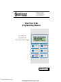
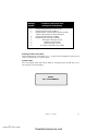
GLOBAL
ACKNOWLEDGE
SILENCE
RESET
TIME
SELECT
TIME SET
DISPLAY STEP
HOLD FOR
LAMP TEST
Local Acknowledge
www.PDF-Zoo.com
firealarmresources.com

Limitations of Fire Alarm Systems
While installing a fire alarm system may make lower insurance
rates possible, it is not a substitute for fire insurance!
Technical Publications PRECAUSM.P65 p1 11/10/99
An automatic fire alarm system
- typically made up of smoke de-
tectors, heat detectors, manual
pull stations, audible warning de-
vices, and a fire alarm control
with remote notification capability
can provide early warning of a
developing fire. Such a system,
however, does not assure protec-
tion against property damage or
loss of life resulting from a fire.
The Manufacturer recommends
that smoke and/or heat detectors
be located throughout a protected
premise following the recommen-
dations of the current edition of
the National Fire Protection Asso-
ciation Standard 72 (NFPA 72),
manufacturer's recommenda-
tions, State and local codes, and
the recommendations contained
in the Guide for Proper Use of
System Smoke Detectors, which
is made available at no charge to
all installing dealers. A study by
the Federal Emergency Manage-
ment Agency (an agency of the
United States government) indi-
cated that smoke detectors may
not go off in as many as 35% of
all fires. While fire alarm systems
are designed to provide early
warning against fire, they do not
guarantee warning or protection
against fire. A fire alarm system
may not provide timely or adequate
warning, or simply may not func-
tion, for a variety of reasons:
Smoke detectors may not sense
fire where smoke cannot reach
the detectors such as in chim-
neys, in or behind walls, on roofs,
or on the other side of closed
doors. Smoke detectors also
may not sense a fire on another
level or floor of a building. A sec-
ond floor detector, for example,
may not sense a first floor or
basement fire.
Particles of combustion or
"smoke" from a developing fire
may not reach the sensing cham-
bers of smoke detectors because:
• Barriers such as closed or par-
tially closed doors, walls, or
chimneys may inhibit particle
or smoke flow.
• Smoke particles may become
"cold", stratify, and not reach
the ceiling or upper walls
where detectors are located.
• Smoke particles may be blown
away from detectors by air out-
lets.
• Smoke detectors may be
drawn into air returns before
reaching the detector.
The amount of "smoke" present
may be insufficient to alarm
smoke detectors. Smoke detec-
tors are designed to alarm at vari-
ous levels of smoke density. If
such density levels are not cre-
ated by a developing fire at the
location of detectors, the detec-
tors will not go into alarm.
Smoke detectors, even when
working properly, have sensing
limitations. Detectors that have
photoelectronic sensing cham-
bers tend to detect smoldering
fires better than flaming fires,
which have little visible smoke.
Detectors that have ionizing-type
sensing chambers tend to detect
fast flaming fires betters than
smoldering fires. Because fires
develop in different ways and are
often unpredictable in their
growth, neither type of detector is
necessarily best and a given type
of detector may not provide ad-
equate warning of a fire.
Smoke detectors cannot be ex-
pected to provide adequate warn-
ing of fires caused by arson, chil-
dren playing with matches (espe-
cially in bedrooms), smoking in
bed, and violent explosions
(caused by escaping gas, im-
proper storage of flammable ma-
terials, etc.).
Heat detectors do not sense par-
ticles of combustion and alarm
only when heat on their sensors
increases at a predetermined rate
or reaches a predetermined level.
Rate-of-Rise heat detectors may
be subject to reduced sensitivity
over time. For this reason, the
rate-of-rise feature of each detec-
tor should be tested at least once
per year by a qualified fire protec-
tion specialist.
Heat detectors
are designed to protect property,
not life.
IMPORTANT!
Smoke detectors
must be installed in the same
room as the control panel and in
rooms used by the system for the
connection of alarm transmission
wiring, communications, signaling,
and/or power.
If detectors are
not so located, a developing fire
may damage the alarm system,
crippling its ability to report a fire.
Audible warning devices such
as bells may not alert people if
these devices are located on the
other side of closed or partly
open doors or are located on an-
other floor of a building. Any
warning device may fail to alert
people with a disability or those
who have recently consumed
drugs, alcohol or medication.
Please note that:
• Strobes can, under certain cir-
cumstances, cause seizures in
people with conditions such as
epilepsy.
• Studies have shown that cer-
tain people, even when they
hear a fire alarm signal, do not
respond or comprehend the
meaning of the signal. It is the
property owner's responsibility
to conduct fire drills and other
training exercise to make
people aware of fire alarm sig-
nals and instruct them on the
proper reaction to alarm sig-
nals.
• In rare instances, the sounding
of a warning device can cause
temporary or permanent hear-
ing loss.
A fire alarm system will not oper-
ate without any electrical power.
If AC power fails, the system will
operate from standby batteries
only for a specified time and only
if the batteries have been prop-
erly maintained and replaced
regularly.
Equipment used in the system
may not be technically compatible
with the control. It is essential to
use only equipment listed for ser-
vice with your control panel.
Telephone lines needed to
transmit alarm signals from a
premise to a central monitoring
station may be out of service or
temporarily disabled. For added
protection against telephone line
failure, backup radio transmission
systems are recommended.
The most common cause of fire
alarm malfunction is inadequate
maintenance. To keep the entire
www.PDF-Zoo.com
firealarmresources.com

Installation Precautions
Adherence to the following will aid in
problem-free installation with long-term reliability:
Technical Publications PRECAUSM.P65 p2 11/10/99
fire alarm system in excellent
working order, ongoing mainte-
nance is required per the
manufacturer's recommendations,
and UL and NFPA standards. At
a minimum the requirements of
Chapter 7 of NFPA 72 shall be
followed. Environments with
large amounts of dust, dirt or high
air velocity require more frequent
maintenance. A maintenance
agreement should be arranged
through the local manufacturer's
representative. Maintenance
should be scheduled monthly or
as required by National and/or
local fire codes and should be
performed by authorized profes-
sional fire alarm installers only.
Adequate written records of all
inspections should be kept.
WARNING -
Several different
sources of power can be con-
nected to the fire alarm control
panel.
Disconnect all sources of
power before servicing. Control
unit and associated equipment
may be damaged by removing
and/or inserting cards, modules,
or interconnecting cables while
the unit is energized. Do not at-
tempt to install, service, or oper-
ate this unit until this manual is
read and understood.
CAUTION -
System Reaccep-
tance Test after Software
Changes
To ensure proper sys-
tem operation, this product must
be tested in accordance with
NFPA 72-1996 Chapter 7 after
any programming operation or
change in site-specific software.
Reacceptance testing is required
after any change, addition or de-
letion of system components, or
after any modification, repair or
adjustment to system hardware
or wiring.
All components, circuits, system
operations, or software functions
known to be affected by a change
must be 100% tested. In addi-
tion, to ensure that other opera-
tions are not inadvertently af-
fected, at least 10% of initiating
devices that are not directly af-
fected by the change, up to a
maximum of 50 devices, must
also be tested and proper system
operation verified.
This system meets NFPA re-
quirements for operation at 0-49º
C/32-120º F and at a relative
humidity of 85% RH (non-con-
densing) at 30º C/86º F. How-
ever, the useful life of the
system's standby batteries and
the electronic components may
be adversely affected by extreme
temperature ranges and humidity.
Therefore, it is recommended that
this system and all peripherals be
installed in an environment with a
nominal room temperature of 15-
27º C/60-80º F.
Verify that wire sizes are ad-
equate for all initiating and indi-
cating device loops. Most de-
vices cannot tolerate more than a
10% I.R. drop from the specified
device voltage.
Like all solid state electronic
devices, this system may oper-
ate erratically or can be damaged
when subjected to lightning in-
duced transients. Although no
system is completely immune
from lightning transients and
interferences, proper grounding
will reduce susceptibility.
Over-
head or outside aerial wiring is
not recommended, due to an in-
creased susceptibility to nearby
lightning strikes.
Consult with the
Technical Services Department if
any problems are anticipated or
encountered.
Disconnect AC power and bat-
teries prior to removing or insert-
ing circuit boards. Failure to do
so can damage circuits.
Remove all electronic assem-
blies prior to any drilling, filing,
reaming, or punching of the en-
closure. When possible, make all
cable entries from the sides or
rear. Before making modifica-
tions, verify that they will not in-
terfere with battery, transformer,
and printed circuit board location.
Do not tighten screw terminals
more than 9 in-lbs. Over tighten-
ing may damage threads, result-
ing in reduced terminal contact
pressure and difficulty with screw
terminal removal.
Though designed to last many
years, system components can
fail at any time. This system con-
tains static-sensitive components.
Always ground yourself with a
proper wrist strap before handling
any circuits so that static charges
are removed from the body. Use
static suppressive packaging to
protect electronic assemblies
removed from the unit.
Follow the instructions in the
installation, operating, and pro-
gramming manuals. These in-
structions must be followed to
avoid damage to the control panel
and associated equipment. FACP
operation and reliability depend
upon proper installation by autho-
rized personnel.
FCC Warning
WARNING: This equipment
generates, uses, and can radi-
ate radio frequency energy
and if not installed and used in
accordance with the instruc-
tion manual, may cause inter-
ference to radio communica-
tions. It has been tested and
found to comply with the limits
for class A computing device
pursuant to Subpart B of Part
15 of FCC Rules, which is
designed to provide reason-
able protection against such
interference when operated in
a commercial environment.
Operation of this equipment in
a residential area is likely to
cause interference, in which
case the user will be required
to correct the interference at
his own expense.
Canadian Requirements
This digital apparatus does
not exceed the Class A limits
for radiation noise emissions
from digital apparatus set out
in the Radio Interference Reg-
ulations of the Canadian De-
partment of Communications.
Le present appareil numerique
n'emet pas de bruits radio-
electriques depassant les
limites applicables aux
appareils numeriques de la
classe A prescrites dans le
Reglement sur le brouillage
radioelectrique edicte par le
ministere des Communica-
tions du Canada.
www.PDF-Zoo.com
firealarmresources.com

415658 Rev A2 11/05/99
Table of Contents
Installation and Startup...................................................................................5
Introduction ....................................................................................................5
Inventory ........................................................................................................5
Program Installation .......................................................................................5
Getting Started ...............................................................................................5
Connecting an IBM-PC (or compatible) Computer to an LCD-80 ...................6
Starting the Program ......................................................................................8
Main Menu Options .........................................................................................9
1) Display from Disk File ...............................................................................9
2) Display From LCD-80................................................................................9
3) Display Sample File...................................................................................9
4) Copy Codes from Diskfile to LCD-80.........................................................9
5) Copy Codes from LCD-80 .........................................................................9
6) Display Zone Label from AFP-200/ID-200 File ..........................................9
7) Exit to DOS ...............................................................................................9
A) Change Serial Port switches ports from COM 1 to COM 2. ......................9
LCD-80 PROGRAMMING...............................................................................10
Initial Programming ......................................................................................10
The Submenu...............................................................................................10
Label Editing.................................................................................................12
Screen Navigation ........................................................................................12
Saving Programs..........................................................................................13
FILENAMES.................................................................................................14
Editing Programs..........................................................................................14
Loading Labels from a Disk File ...................................................................14
Uploading Labels from the LCD-80 ..............................................................15
Saving Labels to Disk...................................................................................15
Downloading Labels to the LCD-80 ..............................................................15
Display Zone Label from AFP-200/ID-200 DISK FILE ..................................15
Default Messages and System Labels .........................................................16
To restore default point labels ......................................................................16
Entering Custom Point Labels ......................................................................17
System Labels..............................................................................................17
www.PDF-Zoo.com
firealarmresources.com

5
15658 Rev A2 11/05/99
Installation and Startup
Introduction
This manual describes the use of the LCD-80 Programming Utility. Using this
utility,
the LCD-80 can be programmed directly from most IBM PC/XT/AT or compatible
computers, including lap-tops and portables, equipped with a serial port. LCD-80
program
files also can be created and stored on the PC, then downloaded to the
panel.
Note: This program will function only with an LCD-80 having software P/N
73323 or P/N 73448 or higher.
Before attempting to program an LCD-80 with the programming utility, the user should
have a knowledge of basic computer use and MS-DOS command structure. After
creating or modifying an LCD-80 program, the system must be thoroughly tested
with
the software installed and operational. For more information refer to
the LCD-80
Manual (Document 15037).
Inventory
The LCD-80 Off Line Programming Utility contains the following:
• Two low density floppy disks, one 5.25" (p/n 75279), one 3.5" (p/n 75280).
• Cable, 9-pin female to LCD-80 RS-232 connection (p/n 75267).
• Adapter, 9-pin male to 25-pin female (p/n 46029).
Program Installation
You can run the LCD-80 programming application directly either from a
floppy disk or
from a hard disk drive. To install on a hard drive, create a directory called
LCD-80 on
the drive. Copy the files from the floppy drive to this directory.
Getting Started
The LCD-80 Programming Utility can be used in two ways:
On-Line Connect a PC to the LCD-80 and transfer program files between the two
devices.
Off-Line Even when a PC is not connected to the LCD-80, the PC can still be used to
create or modify program files. The files can be stored on magnetic disk for later
transfer to the LCD-80.
www.PDF-Zoo.com
firealarmresources.com

615658 Rev A2 11/05/99
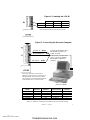
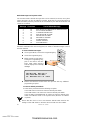
Connecting an IBM-PC (or compatible) Computer to an LCD-80
•Connect the LCD-80 to a 24 VDC Power Source as shown in Figure 1.
•Apply power and verify that a Ground Fault is not present. If a Ground Fault is
present, it
must
be removed before the PC is connected. Connecting a PC to
a system with a Ground Fault may result in damage to the PC, LCD-80 and
the Fire Alarm System.
•Remove power and connect the LCD-80 to the PC, as shown in Figure 2.
•Configure the LCD-80 for ACS Mode.
•Verify that the LCD-80 has Software P/N 73323, P/N 73448 or higher.
•Install the PK-1 Program Key on Connector P6 of LCD-80.
•Apply power to the LCD-80 and the PC.
•Transfer information between the PC and the LCD-80.
•Remove power to the LCD-80 and the PC.
•Disconnect the PC and remove the PK-1 Program Key.
•Install the LCD-80.
•Test the Fire Alarm System.
www.PDF-Zoo.com
firealarmresources.com

7
15658 Rev A2 11/05/99
MPS-24A MPS-24B AFP-200
Common (-) TB3-4 TB2-2 TB1-4
24 VDC (+) TB3-3 TB2-1 TB1-3
Note: Maximum LCD-80 current draw is 100 mA.
Figure 1: Powering the LCD-80
IBM-PC compatible
personal computer
EIA-232 TX Black Connect up/download cable
(NOTIFIER p/n 75267) to
COM1 or COM2.
If the PC has a 25 pin serial
port, a 9 to 25 pin adapter
(NOTIFIER p/n 46029) is
required.
EIA-232 RX Green
EIA-232 Reference Red
Figure 2: Connecting the Personal Computer
Note: Pin 4 (DTR) is connected to pin 6 (DSR) in the 9 pin connector housing.
LCD-80 Wire Color EIA Name 9 PIN Connector 25 PIN
Connector
1Green Tx D 3 2
6Red Signal Ground 5 7
7Black Rx D 2 3
No Connection -DTR 4 (Note 1) 20
No Connection -DSR 6 (Note 1) 6
Note: The LCD-80 does not have to be
physically connected to the PC while you are
editing the labels. The PC and the LCD-80
only need to be connected during the transfer
of files between the PC and the LCD-80.
www.PDF-Zoo.com
firealarmresources.com

815658 Rev A2 11/05/99
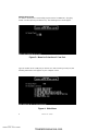
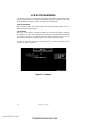
Starting the Program
Use DOS to Start-up the LCD-80 utility program named "LCD80.EXE," by typing
LCD80 and then pressing the Return key. The following menu should appear:
Type the number of the COM port you wish to use. After selecting a COM port, the
following "Main Menu" will appear on your computer screen.
Figure 3: Menu for Selection of Com Port
Figure 4: Main Menu
www.PDF-Zoo.com
firealarmresources.com

9
15658 Rev A2 11/05/99
Main Menu Options
1) Display from Disk File calls an LCD-80 label program stored on disk.
If the file is not in LCD-80 format, you will be informed by the message "NOT LCD-80
FILE."
Note: LCD-80 File is 5341 bytes long. The calculated checksum is 0.
To abort this function, use the ESC key. When the correct file name is entered on the
bottom of screen, the total number of bytes read from the file is displayed. An on-
screen menu will appear. You may choose to view or edit the file.
2) Display From LCD-80 reads labels stored in the LCD-80.
You will be prompted that the process is "COMPLETED" or that an "ERROR" has
been detected. When the process is completed, an on-screen menu will appear. You
may choose to view or edit the file.
3) Display Sample File calls sample labels file stored within LCD80.exe program.
To create new labels, use this selection as a template for your new file. The new file is
created by typing over the information displayed from the sample file. After making
the new file, remember to give it a new name and then save the file on a magnetic
disk.
4) Copy Codes from Diskfile to LCD-80 downloads program created on PC into
LCD-80 memory.
Use this selection to copy files you have stored on disk to an LCD-80. The file is
transferred directly without being displayed.
5) Copy Codes from LCD-80 to Disk File uploads program stored in LCD-80
memory to PC for editing.
In this option, you will be asked to enter a file name. The codes from LCD-80 memory
will be transferred to file without editing or viewing. You will be prompted when that
process is "COMPLETED" or that an "ERROR" has been detected.
6) Display Zone Label from AFP-200/ID-200 File extracts zone labels from AFP-
200/ID-200 file for downloading into LCD-80.
After selecting this option from the main menu, you will be prompted to enter the file
name. You can abort this option by pressing the ESC key. After the correct name has
been entered, an AFP-200 program stored on disk will be checked for compatibility,
otherwise you will receive the message "NOT AFP-200/ID-200 FILE." AFP-200/ID-
200 files are created and saved using the PK-200 off-line programming utility.
7) Exit to DOS leaves the LCD-80 programming utility.
A) Change Serial Port switches ports from COM 1 to COM 2.
www.PDF-Zoo.com
firealarmresources.com

10 15658 Rev A2 11/05/99
LCD-80 PROGRAMMING
This section discusses use of the LCD-80 Programming Utility to create and/or modify
LCD-80 program labels. For additional information about the capabilities of the LCD-
80 programming techniques, please refer the the LCD-80 manual.
Initial Programming
When initially creating an LCD-80 program with the programming utility, select "3)
Display Sample File" by typing 3.
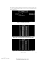
The Submenu
When you choose option 3)
Display Sample File
, the utility will display a submenu
(see Figure 5). In this screen, a submenu gives the option of programming the AIM for
20 character messages, 40 character messages, AFP-200 labels. In other screens,
the submenu displays the available options for modifying other parameters.
Use the Up and Down arrow keys and the Enter key, or enter the number of your
selection on the PC keyboard.
Figure 5: Submenu
www.PDF-Zoo.com
firealarmresources.com

11
15658 Rev A2 11/05/99
After selecting the message format (AIM, 20 character, 40 character, AFP200, select
"P" if you are programming Point labels or select "S" if you are programming System
labels. See Figure 6.
Figure 6: Point/System Labels
Figure 7A: Point Labels with 20 Character Message
Figure 7B: Point Labels with 40 Character Message
www.PDF-Zoo.com
firealarmresources.com

12 15658 Rev A2 11/05/99
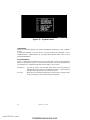
Label Editing
Labels are edited by typing over existing information appearing on your computer
screen.
A point label identifies a zone or device, and may be used for messages such as
"SUPERVISORY," PRE ALARM," etc. A system label indicates status such as: "ALL
SYSTEMS NORMAL."
Screen Navigation
There is a great deal of information to enter or edit in the screens of the programing
utility. To expedite this process, become familiar with the use of the following keys
and submenus to navigate through the various fields in each screen.
Arrow Keys
Use the up, down, left, and right arrow keys to move through the
different fields. After you have completed an entry in a field, pressing
the right arrow key will move you to the next field.
Esc Key
When you have finished programming a Point Label or System Label
screen, pressing the Esc key will bring up submenus.
Figure 7C: System Labels
www.PDF-Zoo.com
firealarmresources.com

13
15658 Rev A2 11/05/99
Saving Programs
After you have finished working in a screen, the application instructs you to press
the
Esc
key. Doing this from the System Code screen, for example, brings up
Figure 8.
P - POINT LABEL
S - SYSTEM LABEL
E - EXIT
P- Point Label Moves you to the Zone Label Code screen for editing.
S- System Label Returns user to the System Label screen.
E- Exit Choosing Exit brings up another submenu (Figure 9).
P - PRINT
S - SAVE
D - DOWNLOAD
M - MAIN MENU
P- Print Sends the completed program to a printer attached directly
to the PC.
Note: Do not make this choice if a printer is not
attached to the PC.
S- Save Saves your program to disk. The application will prompt you
to name the file. Name the file, press Enter, and the file will
be
saved to disk.
D- Download Downloads the program to an LCD-80 connected to the PC.
It is recommended that you save the program to disk before
down loading it.
Note: Do not make this choice if an LCD-80 is
not attached to the PC.
M- Main Menu Returns you to the main menu (without saving the pro-
gram.)
www.PDF-Zoo.com
firealarmresources.com

14 15658 Rev A2 11/05/99
FILENAMES
When the LCD-80 Programming Utility prompts you to enter a filename you should
enter the file location and file name including its extension. The program will use the
current drive and current directory unless a location is specified.
Examples:
AIRPORT :
Refers to the file “AIRPORT” in the current drive and current directory.
AIRPORT.JOB :
Refers to the file “AIRPORT.JOB” in the current drive and current
directory.
C:\LCD80\LABELS\AIRPORT.JOB :
Refers to the file “AIRPORT.JOB” in the sub-
directory called LABELS that is contained in the directory LCD80 on drive “C.”
The names you choose for files and extensions must comply with the following:
• Filename can have a maximum of eight characters.
• Extension can have a maximum of three characters.
• Filename must appear before the extension.
• A period must separate filename from extension.
• Contain only the letters A through Z, the numbers 0 through 9, and the
following special characters: underscore (_), caret (^), dollar sign ($), tilde (~),
exclamation point (!), number sign (#), percent sign (%), ampersand (&),
hyphen (-), braces ({}), parentheses ( ), at sign (@), apostrophe (’), and the
grave accent (‘). No other special characters are acceptable.
• Not contain spaces, commas, backslashes, or periods (except the period that
separates the name from the extension).
• Not be the following reserved filenames: CLOCK$, CON, AUX, COM
n
(where
n
= 1— 4), LPT
n
(where
n
= 1 — 3), NUL, and PRN.
Editing Programs
Use Main Menu option
"1) Display From Diskfile,"
to call up an existing LCD-80
program stored on disk. The application will prompt you to enter the file name. To
make the file available for editing, enter the file name and then press the Enter key.
Loading Labels from a Disk File
First determine the name and location of file to be loaded.
From the Main Menu, choose "1) DISPLAY FROM DISKFILE."
On the bottom of the screen, a prompt will ask for the name of the file to be displayed.
Type in the file name including its extension. If the file does not exist, you will be
prompted to enter a new name. You can return to the Main Menu by pressing the
"
Esc
" key.
www.PDF-Zoo.com
firealarmresources.com

15
15658 Rev A2 11/05/99
Uploading Labels from the LCD-80
Either one of these options can be chosen from the Main Menu:
"2) DISPLAY FROM LCD-80" In Option 2, the codes will be transferred to PC
memory. If Process is completed, follow the screen menu, the file could be dis-
played for editing or viewing.
"5) COPY CODES FROM LCD-80 TO DISK FILE" In Option 5, you will be asked to
enter file name, then the codes from LCD-80 memory will be transferred to file
without editing or viewing. If the process is completed successfully, you will be
given the message "COMPLETED." Otherwise, you will be given the message
"ERROR."
During Upload of labels from the LCD-80, a number will be incremented at the bottom
of the screen. When you are done editing labels on a screen, press the "Esc" key.
You will then see a menu. Choose "Exit" if you wish to reach the menu for choosing
"
print,
" "
save,
" or "
download.
"
Saving Labels to Disk
We recommend saving edited labels to disk prior to printing or downloading. To save
the label data, choose "Save" from the menu. You will be asked to type a file name
and then press "
Enter.
" While the labels are being saved to disk, a number will be
incremented at the bottom of the screen. When the process of saving your file to disk
is complete, you should see the message: "Save file filename is complete." Press the
"Enter" key to continue.
Downloading Labels to the LCD-80
Labels could be downloaded to LCD-80 memory by:
1) Transferring directly from LCD-80 label program file using Option "4) COPY
CODES FROM DISK FILE TO LCD-80"; or
2) When LCD-80 program file is displayed on screen: Exit Edit Mode and select
"DOWNLOAD".
While the labels are being downloaded to the LCD-80, a number will be incremented
at the bottom of the screen. When downloading to the LCD-80 is complete, you
should see the message: "DOWNLOAD TO LCD-80 IS COMPLETE."
Display Zone Label from AFP-200/ID-200 DISK FILE
After selecting this option from main menu, you will be prompted to enter a
filename.
If you do not wish to enter a
filename
, press the Esc key. After entering a valid
filename, an AFP-200/ID-200 program stored on disk will be checked to determine if
it is an AFP-200/ID-200 file. If it is not, you will be given the message "NOT AFP-200/
ID-200 FILE."
Note: AFP-200/ID-200 file is 10,449 bytes long and the calculated checksum is 0.
You can now edit these labels for use with an LCD-80. After editing, the new file can
be saved as an LCD-80 file and downloaded to an LCD-80.
www.PDF-Zoo.com
firealarmresources.com

16 15658 Rev A2 11/05/99
Default Messages and System Labels
The LCD-80 contains default messages that can be restored (en masse) at any time.
These messages can also be edited as needed. Note that any custom messages or
labels that were previously entered will be overwritten by the default information and
cannot be recovered.
Message
1
2
3
4
5
6
7
8
9
Characters
40
20
40
20
20
20
20
20
20
Text of Default Message
"FIRE ALARM SYSTEM REMOTE ANNUNCIATOR"
"ALL SYSTEMS NORMAL"
"COMMUNICATIONS FAIL"
"FIRE ALARM IN SYSTEM"
"TROUBLE IN SYSTEM"
"RETURN TO NORMAL"
"ACKNOWLEDGE"
"SIGNAL SILENCE"
"SYSTEM RESET"
AM2020/AFP1010 Note: When the LCD-80 is used in conjunction with an AM2020/
AFP1010 combination fire and security panel, the "FIRE" in default messages 1 and 4
must be removed.
✓✓
✓✓
✓Release the DISPLAY STEP switch and proceed with any additional
programming required.
To restore default point labels:
Use the above procedure with the following exception:
Push TIME SET to restore 20-character default point labels.
Push TIME SELECT to restore 40–character default point labels.
Push GLOBAL ACKNOWLEDGE to restore 20-character default point
labels for AIM-200 mode in the System 5000 (Revision 6 software
required).
Ensure that the choice of 20 or 40-character default labels matches the
settings on the SIZE SELECT switches SW-5 and SW-6 on the LCD-80.
To restore default messages:
✓✓
✓✓
✓If in Program Mode, remove the Programming Key.
✓✓
✓✓
✓Insert the Programming Key.
✓✓
✓✓
✓Within several seconds after in-
serting the Programming Key,
push in and hold in the DIS-
PLAY STEP switch until the
LCD-80 displays the following
message:
T R A N S FE R DE F A U L T
C U S T OM M E S S A GE S
TO NONVOLATI LE RAM
www.PDF-Zoo.com
firealarmresources.com

17
15658 Rev A2 11/05/99
Message
Number
1
2
3
4
5
6
7
8
9
Conditions under which each
message will be displayed.
Standard display banner for the LCD-80.
Displayed under normal conditions.
Displayed when communications between LCD-80
and the control panel have been interrupted.
Displayed under all alarm conditions.
Displayed under all trouble conditions.
Messages 6 through 9 are not
displayed on the LCD-80.
These messages are sent
to a printer connected to the LCD-80.
Entering Custom Point Labels
From the Main Menu, select option 1, 2, or 3. Then a menu will appear to give you the
choice of editing Point or System Labels.
System Labels
Once in Program mode, the LCD-80 waits for commands from the EIA-232 circuit.
The LCD-80 screen will display:
READY
FOR PROGRAMMING
www.PDF-Zoo.com
firealarmresources.com

18 15658 Rev A2 11/05/99
Notes
www.PDF-Zoo.com
firealarmresources.com

19
15658 Rev A2 11/05/99
Notes
www.PDF-Zoo.com
firealarmresources.com

Limited Warranty
NOTIFIER® warrants its products to be free from defects in materials and
workmanship for eighteen (18) months from the date of manufacture, under normal
use and service. Products are date stamped at time of manufacture. The sole and
exclusive obligation of NOTIFIER® is to repair or replace, at its option, free of charge
for parts and labor, any part which is defective in materials or workmanship under
normal use and service. For products not under NOTIFIER® manufacturing date-
stamp control, the warranty is eighteen (18) months from date of original purchase
by NOTIFIER®'s distributor unless the installation instructions or catalog sets forth
a shorter period, in which case the shorter period shall apply. This warranty is void
if the product is altered, repaired or serviced by anyone other than NOTIFIER® or
its authorized distributors or if there is a failure to maintain the products and systems
in which they operate in a proper and workable manner. In case of defect, secure
a Return Material Authorization form from our customer service department. Return
product, transportation prepaid, to NOTIFIER®, One Fire-Lite Place, Northford,
Connecticut 06472-1653.
This writing constitutes the only warranty made by NOTIFIER® with respect to its
products. NOTIFIER® does not represent that its products will prevent any loss by
fire or otherwise, or that its products will in all cases provide the protection for
which they are installed or intended. Buyer acknowledges that NOTIFIER® is not
an insurer and assumes no risk for loss or damages or the cost of any inconvenience,
transportation, damage, misuse, abuse, accident or similar incident.
NOTIFIER® GIVES NO WARRANTY, EXPRESSED OR IMPLIED, OF
MERCHANTABILITY, FITNESS FOR ANY PARTICULAR PURPOSE, OR
OTHERWISE WHICH EXTEND BEYOND THE DESCRIPTION ON THE FACE
HEREOF. UNDER NO CIRCUMSTANCES SHALL NOTIFIER® BE LIABLE FOR
ANY LOSS OF OR DAMAGE TO PROPERTY, DIRECT, INCIDENTAL OR
CONSEQUENTIAL, ARISING OUT OF THE USE OF, OR INABILITY TO
USE NOTIFIER® PRODUCTS. FURTHERMORE, NOTIFIER® SHALL NOT BE
LIABLE FOR ANY PERSONAL INJURY OR DEATH WHICH MAY ARISE IN THE
COURSE OF, OR AS A RESULT OF, PERSONAL, COMMERCIAL OR INDUSTRIAL
USE OF ITS PRODUCTS.
This warranty replaces all previous warranties and is the only warranty made by
NOTIFIER®. No increase or alteration, written or verbal, of the obligation of this
warranty is authorized.
"NOTIFIER" is a registered trademark.
Technical Publishing Document WARNSM-E1.P65 11/24/1999
One Fire-Lite Place
Northford, CT 06472
Phone: (203) 484-7161
FAX: (203) 484-7118
www.PDF-Zoo.com
firealarmresources.com
-
 1
1
-
 2
2
-
 3
3
-
 4
4
-
 5
5
-
 6
6
-
 7
7
-
 8
8
-
 9
9
-
 10
10
-
 11
11
-
 12
12
-
 13
13
-
 14
14
-
 15
15
-
 16
16
-
 17
17
-
 18
18
-
 19
19
-
 20
20


Notifier PK-LCD-80 Programmable Fire Alarm Control Panels Owner's manual
- Category
- Fire protection
- Type
- Owner's manual
Ask a question and I''ll find the answer in the document
Finding information in a document is now easier with AI