Viper FANG 20 Owner's manual
- Category
- Floor Machine
- Type
- Owner's manual
This manual is also suitable for


CONGRATULATIONS on your purchase of a Viper product, and welcome to the V.I.P.
family. We appreciate your business and will do every-thing in our power to keep you
happy with your purchase for many years to come.
As part of the V.I.P. family, you are entitled to the best protection by one of the most
comprehensive warranties in the industry.
Thank-you for purchasing Viper products!
Tom VanderBie, CEO
TABLE OF CONTENTS
SAFETY PRECAUTIONS 3
MACHINE COMPONENTS 4
MACHINE SET UP 5
MACHINE INSTALLATION 5-6
MACHINE OPERATION 6
TANK DRAINING 7
BATTERY CHARGING 7-8
PREVENTATIVE MAINTENANCE 8-9
MACHINE STORAGE 9
BASIC TROUBLESHOOTING 10
PARTS BREAKDOWNS AND LISTS 11-31
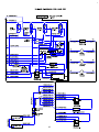
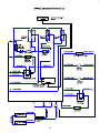
WIRING DIAGRAM 32-33
2

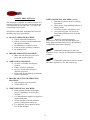
SAFETY PRECAUTIONS
This machine is intended for commercial use. It is
constructed for use in an indoor environment and
is not intended for any other use. Use only with
recommended accessories.
All operators shall read, understand and exercise
the following safety precautions:
1) DO NOT OPERATE MACHINE:
x Unless trained and authorized.
x Unless you have read and understand
the operators manual.
x In flammable or explosive areas.
x If not in proper operating condition.
x In outdoor areas.
2) BEFORE OPERATING MACHINE:
x Make sure all safety devices are in
place and operate properly.
3) WHEN USING MACHINE:
x Go slow on inclines and slippery
surfaces.
x Follow all safety guidelines.
x Be very careful when using the
machine in reverse.
x Report and fix any damage to machine
prior to operating it.
4) BEFORE LEAVING OR SERVICING
MACHINE:
x Stop machine on level ground.
x Turn machine off.
5) WHEN SERVICING MACHINE:
x Read operators manual thoroughly
prior to operating or servicing this
machine.
x Use manufacturer supplied or approved
replacement parts.
x Secure machine with wheel blocks
prior to jacking the machine up.
x Use approved jack or hoist to safely
elevate the machine.
WHEN SERVICING MACHINE: (con’t)
x Disconnect batteries prior to working
on machine.
x Wear gloves when handling batteries or
battery cables.
x
Avoid any contact with battery acid.
x Avoid moving parts. Do not wear
loose fitting clothing while servicing
machine.
: Batteries emit hydrogen gas.
Explosion or fire can result from hydrogen gas.
Keep sparks and open flames away! Keep battery
compartment open when charging.
: Flammable materials can cause an
explosion or fire. Do not use flammable materials
in tanks.
: Flammable materials or reactive metals
can cause explosion or fire. Do not pick up.
3

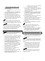
MACHINE COMPONENTS
1. Vacuum ON/OFF switch
2. Brush ON/OFF switch
3. Battery level meter
4. Solution ON/OFF switch
5. Solution control knob
6. Recovery tank drain hose
7. Squeegee assembly
8. Brush lift foot pedal
9. Solution tank level sight tube
10. Console adjustment levers
11. Rear solution fill
12. Circuit breakers
13. Squeegee lift lever
14. Control housing
15. Solution tank
16. Transport wheels
17. Scrub head
18. Scrub head skirt
19.
Protective rollers
20. Front sol
ution fill
21. Recovery tank
22. Recovery tank lid
23. Operating triggers
24. Main power ON/OFF switch
25. Reverse switch
26. Speed control knob
20
21
22
23
14
13
11
15
16
1718
19
13
2 3 4
12
11
10
9
8
5
6
1
7
24
4
3
26
25
1
12
2
4

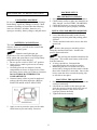
MACHINE SET UP &INSTALLATION
UNCRATING MACHINE
Be sure and check packing carton for any damage.
Immediately report any damage to carrier. Check
contents of package to ensure that the following
items are included: Machine, batteries (x2),
squeegee assembly, battery charger, and pad driver.
BATTERY CONNECTIONS
The batteries are already in the machine upon
delivery; however, you will need to connect the
cables to the battery posts.
: Batteries emit hydrogen gas.
Explosion or fire can result from hydrogen gas.
Keep sparks and open flames away! Keep battery
compartment open when charging.
1. Be sure power switch is in the “off” position.
2. Open recovery tank to gain access to battery
compartment.
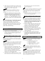
3. Carefully place the two batteries into the
compartment as shown in figure below. Place
the battery brace at the rear of the two batteries.
DO NOT DROP BATTERIES INTO
COMPARTMENT!
4. Connect battery cables to posts in numbered
order as shown in drawing below. (RED to
POSITIVE and BLACK to NEGATIVE)
5. Apply a coat or protective spray on the cable
connections to prevent battery corrosion.
MACHINE SET UP
PRE-OPERATION CHECKS
1. Sweep or dust mop the surface to be cleaned.
2. Check battery meter to make sure batteries are
fully charged. (see BATTERY CHARGING)
3. Check that squeegee is properly installed.
4. Check that brush / pad is properly installed.
INSTALLING PAD DRIVER OR BRUSH
1. Ensure that the machine is turned off
2. Lower brush head assembly to the floor by
stepping on the foot pedal and pushing pedal
forward.
3. Tilt the machine backward to access the drive
motor hub.
: Remove the squeegee assembly prior to
tilting the machine backwards. It makes the
process faster and easier.
: Do not keep the machine tilted back for
a long time. This could cause battery acid to leak
from the batteries.
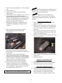
4. If using a pad driver, first attach the
appropriate pad to the pad driver surface.
5. Mount the pad driver or brush to the drive
motor hub by lining up the three studs with the
three holes in the drive motor hub. Once in the
holes, rotate the driver toward the spring clip
to lock driver into place.
MOUNTING THE SQUEEGEE
1. Pull back on the squeegee lift lever to raise the
squeegee bracket up.
2. Loosen the two knobs on the squeegee and
slide the squeegee into the slots at the rear of
the squeegee bracket. (the wheels on the
squeegee point to the back)
3. Tighten the knobs securely.
.
5

FILLING THE SOLUTION TANK
1. The Fang 20 / 20T can be filled in two
different locations:
a. Front fill area for use with a hose or a
bucket.
b. Rear fill area for use with a hose only.
2. Determine which fill area you would like to
use to fill the machine with water.
3. Fill solution tank with up to 13 gallons of
water. (water temperature should not exceed
140° F) The clear tube in the back left of the
machine has gallon markers to help determine
the water level in the solution tank
: If you are filling the solution tank with a
bucket, make sure the bucket is clean. This will
prevent debris from clogging the lines or solenoid.
: Do not put any flammable materials
into solution tank. This can cause an explosion or
a fire. Only use recommended cleaning chemicals.
Contact your janitorial supply distributor for
recommendations on proper chemicals.
MACHINE OPERATION
: Do not operate machine unless you
have read and understand this manual.
1. Set control housing to a comfortable operating
height by squeezing together the two thumb
levers directly underneath the housing. (see
machine components, item #10)
2. Lower squeegee assembly to the floor by
releasing the lift lever from its locked position.
(see machine components, item #13)
3. Lower brush head assembly to the floor by
stepping on the foot pedal and pushing pedal
forward. (see machine components, item #8)
4. Turn main power to “on” position.(see
machine components,item#24)
5. Turn brush motor to “on” position. (see
machine components, item #2)
6. Turn vacuum motor switch to “on” position.
(see machine components, item #1)
7. Turn the solution switch to “on” position. (see
machine components, item #4)
a. Solution will not begin to flow until the
operating triggers are pulled.
8. The Fang 20T is self-propelled.The speed can
be controlled by a dial located on the right side
of the control housing.(see machine
components,item #26)
9. The Fang 20T has reverse.In order to activate
reverse,there is a toggle switch located on the
left side of the control housing.(see machine
components,item #25)
10. To begin scrubbing, pull on one or both of the
red operating triggers. (see machine
components, item #23) When these triggers are
pulled, the brush will begin to spin and the
solution will begin to flow.The Fang 20T will
propel itself.
11. The Fang 20 Begin scrubbing by moving the
machine forward.
: Do not keep the machine in the same
position with the pad / brush spinning, or you
could cause damage to the floor.
12. Adjust amount of solution flow by turning the
solution control knob. Turn to the right for
more solution, or turn left for less solution.
(see machine components, item #5)
WHILE OPERATING MACHINE
1. Occasionally look through the clear recovery
tank lid to see if there is any foam build-up. If
excessive foam is found, add defoamer to the
recovery tank.
: Foam must not enter the float shut-off
screen, or damage can occur to the vacuum motor.
Foam will not activate the machines float shut-off
device.
2. Occasionally view the clear tube at the back
left of the machine to check the amount of
cleaning solution that is left in the machine.
3. Occasionally check the battery level meter.
(see machine components, item #3) When
meter is in the red, recharge the batteries.
: When battery meter is in the red, do
not continue to operate the machine. Battery
damage may result.
6

4. If the squeegee assembly leaves streaks on the
floor, raise the squeegee off the floor and wipe
the blades down with a damp cloth.
: Do not use your fingers to wipe or
remove debris from the blades, as injury may
occur.
5. When the solution tank runs empty, turn off
the brush switch, solution switch and raise the
brush head. Keep the squeegee down and
continue to vacuum until all the dirty water is
picked up. (see TANK DRAINING section to
learn how to drain recovery and solution tanks)
: The brush motor is circuit breaker protected
to protect it from damage. If this breaker trips, it
can’t be reset immediately. You must first
determine what caused the breaker to trip, and
allow the motor to cool down before you can reset
the breaker. The breaker is located on the back
panel of the control housing.
TANK DRAINING
1. Turn the power off on the machine
2. With the squeegee and brush head in their “up”
position, transport machine to approved area
for draining tank(s).
DRAINING THE RECOVERY (DIRTY) TANK
: Any time scrubbing is completed, or when
refilling solution tank, the recovery tank should be
drained and cleaned.
: If the recovery tank is not drained when
the solution tank has been refilled, foam or water
may enter the float shut-off mechanism and cause
damage to the vacuum motor.
1. Remove the drain hose from the holder, and
place the drain hose over the floor drain. Twist
off the drain hose plug to begin the draining
process. In order to completely empty the
recovery tank, hinge opens the recovery tank
and let it rest on the support stand.
2. Clean the recovery tank after every use. Use a
fresh water hose to rinse out the recovery tank.
Be careful not to spray water into the float
shut-off mechanism.
: If you are storing the machine for any period
of time, always leave the clear recovery tank lid
off the tank so the tank can dry completely and
smell fresh.
3. Replace the drain hose plug tightly as soon as
you are done draining the tank.
DRAINING THE SOLUTION (CLEAN) TANK
: Any time scrubbing operation is completed,
the solution tank should be drained and cleaned.
1. Pull down on the clear tube (back left of the
machine) to remove it from the hose barb. This
will allow the solution to flow freely into a
bucket or floor drain.
2. Rinse the solution tank with clean water after
every use. This will help prevent chemical
buildup and clogging of the solution lines.
3. With clean water in solution tank, turn
machine power on, solution switch “on” and
pull the operating triggers. This will allow the
clean water to flush through and clean the
solution plumbing.
4. Once tank is rinsed, flushed and drained,
reconnect the clear tube to the hose barb. Be
sure the tube is pushed all the way up on the
hose barb.
BATTERY CHARGING
: Use only approved chargers with the
following specifications:
x Automatic shut off circuit
x Deep cycle charging
x Output current of 10 – 20 amps
x Output voltage of 24 volts
: For the best machine performance, keep
batteries charged at all times. Do not let them sit
in a discharged condition.
: Batteries are dangerous! Batteries emit
hydrogen gas and an explosion or fire can result.
Keep sparks and fire away from batteries at all
times. When charging the machine, make sure the
battery compartment is left open.
7

1. Place charger and machine in a well ventilated
area.
2. Turn machine off.
3. Open recovery tank up, exposing battery
compartment
4. Check fluid level in each battery cell. Do not
charge batteries unless fluid is slightly
covering the battery plates. Do not overfill the
batteries. Overfilling may cause the batteries to
overflow during charging due to expansion.
Replace the caps prior to charging.
5. Plug approved charger into grounded wall
outlet before plugging the charger into the
machine.
6. Plug charger into red charger receptacle
located in the front left of the battery
compartment.
7. Flip up the recovery tank “kick stand” and
gently lay the recovery tank down until it rests
on the stand.
8. The charger will automatically begin to
charger the batteries, and it will automatically
shut down once the batteries are fully charged.
9. Upon completion of charging, first unplug the
charger from the wall outlet, and then
disconnect the charger from the machine.
10. Check the battery level after charging is
complete. If fluid level is low, add distilled
water to bring the fluid level up to the bottom
of the sight tubes. Replace the caps and wipe
the batteries down with a towel.
PREVENTATIVE MAINTENANCE
: Before performing any maintenance on
the machine, be sure that the power is turned off,
or the batteries are disconnected!
: Repairs are to be completed by
Authorized Service Centers only. Any repairs
completed by unauthorized persons will void the
warranty.
DAILY MAINTENANCE
1. Remove pad driver / brush and clean with
approved cleaner.
2. Drain recovery and solution tanks completely
and rinse out with clean water. Visually check
the recovery tank for debris and clean out as
necessary.
3. Raise squeegee assembly off floor and wipe it
down with a damp towel. Be sure to store the
squeegee in the up position.
4. Remove the float shut-off assembly and rinse it
out with clean water.
5. Clean machine with an approved cleaner and a
damp towel.
6. Recharge batteries.
WEEKLY MAINTENANCE
1. Check fluid level in batteries.
2. Check batteries for loose or corroded cables.
3. Keep battery tops clean from corrosion.
MONTHLY MAINTENANCE
1. Check machine for leaks and loose fasteners.
2. Lubricate all grease points and pivot points
with silicon spray and approved grease.
3. Place machine over a floor drain. Flush
solution system by pouring 3 gallons of hot
8

water and approved alkaline detergent into the
solution tank and running machine (with
solution control on) for 45 seconds. Turn
machine off and let it sit overnight. Then next
day, drain the remaining solution and rinse the
solution tank out with clean water.
VACUUM MOTOR MAINTENANCE
1. Contact your local Viper Distributor for any
motor maintenance.
2. Vacuum motor should have the brushes
checked every 250 hours. Brushes should be
replaced when they are worn to a length of
10mm or less.
BATTERY MAINTENANCE
: For the best machine performance, keep
batteries charged at all times. Do not let them sit
in a discharged condition.
: Batteries are dangerous! Batteries emit
hydrogen gas and an explosion or fire can result.
Keep sparks and fire away from batteries at all
times.
: Whenever servicing batteries, be sure
to wear protective gloves. Avoid contact with
battery acid at all times!
1. Always follow the battery charging directions
as outlined in the BATTERY CHARGING
section of this manual.
2. Keep battery tops and terminals free from
corrosion. A strong solution of baking soda
and water is the best way to keep the batteries
corrosion free. DO NOT ALLOW THE
BAKING SODA / WATER SOLUTION TO
ENTER THE BATTERY CELLS.
3. Use a wire brush with the baking soda solution
to properly clean the battery posts and
connections.
4. Check battery connections for wear and loose
terminals. Replace if necessary.
MACHINE STORAGE
1. Always store the machine indoors.
2. Always store the machine in a dry area.
3. Always store the machine in its upright
position.
4. Always store the machine with the pad driver /
brush raised off the floor.
5. Always store the machine with the squeegee
assembly raised off the floor.
6. If storing in an area which may reach freezing
temperatures, be sure to drain all fluids from
the machine prior to storage. Any damage
caused by freezing temperatures will not be
covered by the warranty.
7. Drain the recovery tank and remove the clear
on the top of the recovery tank so that it can
“breathe” during storage.
8. Drain the solution tank of all fluid.
9

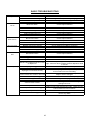
PROBLEM CAUSE SOLUTION
No power Bad batteries Replace batteries
Batteries need to be charged Charge batteries (see Battery Charging)
Loose battery cable Tighten loose cable(s)
Batteries not connected properly Follow battery installation instructions
Brush motor does
not run
Bad brush switch Contact Viper Distributor
Brush circuit breaker has tripped Check brush motor for obstructions and reset breaker
Rectifier has burned out Contact Viper Distributor
Bad wiring Contact Viper Distributor
Bad brush motor Contact Viper Distributor
Carbon brushes worn out Contact Viper Distributor
Bad solenoid Contact Viper Distributor
Vacuum motor
does not run
Bad vacuum switch Contact Viper Distributor
Bad wiring Contact Viper Distributor
Bad vacuum motor Contact Viper Distributor
Carbon brushes worn out Contact Viper Distributor
Short run time Batteries need to be charged Charge batteries (see Battery Charging)
Batteries need maintenance See Battery Maintenance in this manual
Bad cell in battery(s) Replace batteries
Bad charger Replace charger
Little or no solution
flow
Bad solution switch Contact Viper Distributor
Clogged solution solenoid Contact Viper Distributor
Clogged solution filter Remove filter and clean
Solution line obstructed Remove solution line and clean
Solution flow adjustment knob in need
of adjustment
Increase flow by twisting solution adjustment knob to the
right. Decrease flow by twisting solution adjustment knob
to the left.
Poor water pick up Squeegee clogged Clean debris off squeegee with damp towel
Squeegee blades worn Install new squeegee blades
Squeegee not mounted correctly
Confirm that the squeegee assembly is securely fastened
to the machine and not loose fitting.
Vacuum hoses have a hole or are loose
Check hose connections and make sure they are firm.
Replace hose if damaged.
Vacuum hose may be clogged Check hose for debris and remove any clog.
Drain hose stopper is loose Tighten drain plug.
Batteries need to be charged Charge batteries (see Battery Charging)
Vacuum motor is loose
Tighten vac motor mounting screws. Do not overtighten or
damage will occur.
Recovery tank lid is loose Confirm the clear recovery tank lid is securely in place.
Recovery tank inlet hole is clogged
Drain recovery tank and tilt tank on side. Check the inlet
hole for debris and remove debris.
Recovery tank is full Drain recovery tank.
Float shut off is clogged
Remove float shut off from inside recovery tank and
remove any debris.
BASIC TROUBLESHOOTING
10


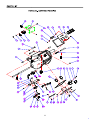
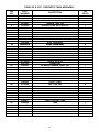
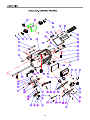
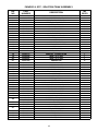
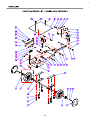
DIA
NO
PART
NUMBER
DESCRIPTION
NO
REQ'D
1
VF81713
BUSHING 2
2 VF14122 WASHER,PLAIN,M10XM20X2 2
3
VF14121
SCREW,M10X65 2
4
VF13502
NUT,LOCK,M6 10
5
GT13032
WASHER,PLAIN,M6 2
VF81781
DIODE,400V 3
VF81781-X
DIODE WITH ENDS 3
7
VF81726A
SOLENOID,24V 2
8
VF81734
BREAKER,CIRCUIT,35 AMP 2
9
VF83149
LABEL,CIRCUIT BREAKER 1
10
VF82108
HOUSING,CONTROL 1
11
VF14078
SCREW,M3X10 6
12
VA50477
WASHER,PLAIN,M3XM10X1 6
13 VF81718
LIGHTS,BATTERY CAPACITY 1
14
VF13495
SCREW,M6X16 4
15
VF82313
GASKET 1
16
VF81719
SPACER 6
17
VF82102A
PANEL,SWITCH 1
18
VF82103A
LABEL,SWITCH 1
19
VF81721
SWITCH,LIGHTED ROCKER 3
20
VF14200
SCREW,M6X16 12
21
VF81709
PIN,HANDLE LOCK 2
22
VF81716
SPRING 1
23
VF81710
PIN,HANDLE ADJUSTMENT 2
24
VF81744B
STRAIN RELIEF,CORD 1
25
VF82312
GASKET 1
26
VF82085
SERIAL TAG 1
27
GV40239
COVER 1
28
VF83148
LABEL,CIRCUIT BREAKER 1
29
VF82303A
PANEL,CONTROL HOUSING 1
30
VF81703
BATTERY CAPACITY,CONTROL BOARD 1
31
VF82107BD
HANDLE,RIGHT 1
32
VF81711
BOLT,SHOULDER M8XM15XM6 2
33
VF81712
SPRING 1
34
VF13491
SCREW,M4X12 1
35
VF13514A
WASHER,PLAIN,M8XM16.5X1 2
36
VF82106BD
HANDLE,LEFT
1
37 VF14212
SCREW,M3X25 2
38 VF13511
WASHER,TOOTH,M3 2
39 VF44203
SWITCH ASSEMBLY 1
40 VF81707
BRACKET,SWITCH 1
41 VV13652
NUT,LOCK,M3 2
42 VF81714
TUBE,HANDLE,ADJUSTMENT 1
43 VF82153
SWITCH,KEY 1
44 VF82160
LABEL,KEY SWITCH 1
45 VF99012
BREAKER,CIRCUIT,12 AMP 1
FANG20 - CONTROL HOUSING
6
12


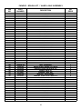
DIA
NO
PART
NUMBER
DESCRIPTION
NO
REQ'D
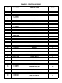
FANG 20 & 20T - RECOVERY TANK ASSEMBLY
1
VF82010 CLEAR COVER, RECOVERY TANK
1
2
VF82083 DECAL, BATTERY WARNING
1
3
VF82009 ELBOW ADAPTOR, FLOAT
1
4
VV13607 WASHER, LOCK, M6
13
5
VF13533 WASHER, PLAIN, M6 X M16 X 2
7
6
VF14233 SCREW, M6 X 20
4
7
VF81504 FLOA
T
1
8
VF82002 RECOVERY TANK
1
9
VF13528 WASHER, TOOTH, LOCK, M6
2
10
VF13495 SCREW, M6 X 16
2
11
VF82028 CABLE
1
12
VF81509 PLUG, EXPANSION
1
13
VF81510 9
STRAP DRAIN HOSE
1
13
VF81510
-
9
STRAP
,
DRAIN
HOSE
1
14
VF81510-2 SLEEVE, DRAIN HOSE
1
15
VF81510A DRAIN HOSE ASSEMBLY
1
16
VF82115 DECAL, BATTERY INSTALLATION
1
17
VF82318 HOOK, CABLE
4
18
VF82326 MESH COVER, CABLE
1
19
VV10113 CLAMP, 2"
2
20
VF14225A SCREW, M6 X 40
4
21
VF81723 CONNECTOR
1
22
VF82331 ON BOARD CHARGER, 9AMP, 24V
1
23
VF82332A KIT,CHARGER REPLACEMENT
1
24
VV13601 WASHER, LOCK, M5
4
25
VF13532 WASHER, PLAIN, M5 X M11 X 2
4
26
VV20501
SCREW M5 X 14
4
26
VV20501
SCREW
,
M5
X
14
4
27
VF82331A KIT, ON BOARD CHARGER
1
28
VF82332 CLAMP, CHARGER
2
29
VF82320 CLAMP, CABLE
2
30
VF13502 NUT, LOCK, M6
3
31
VF82310 STUD
3
32
ZD53000
MOTOR, VACUUM, 2 STAGE, 24VDC
1
ZD53000
MOTOR,
VACUUM,
2
STAGE,
24VDC
33
VF13521 NUT,M6
3
34
VF81503 SEAT
1
35
VF14200 SCREW, M6 X 16
9
36
GT13032 WASHER, PLAIN, M6 X M16 X 1.5
9
37
VF82011 HINGE, RECOVERY TANK
1
38
VF82082 LOGO
1
39
VA13477 SCREW, SELF-TAPPING, ST, M4 X 16
4
40
VV13664 WASHER, PLAIN, M4 X M12 X 1
4
41
VF82010A RUBBER HINGE
1
42
VF82010B GASKET
1
43
VF82010X KIT,LID
1
14

15

DIA
NO
PART
NUMBER
DESCRIPTION
NO
REQ'D
FANG 20T - CONTROL HOUSING
1
VF81713 BUSHING
2
2
VF13491 SCREW, M4 X 12
7
3
VF14122 WASHER, PLAIN, M10 X M20 X 2
2
4
VF14121 SCREW, M10 X 65
2
5
VF13502 NUT, LOCK, M6
10
6
GT13032 WASHER, PLAIN, M6
6
VF81781 DIODE, 400V
3
VF81781 X
DIODE WITH ENDS
3
7
VF81781
-
X
DIODE
WITH
ENDS
3
8
VF81726A SOLENOID, 24V
3
9
VF81734 BREAKER, CIRCUIT, 35 AMP
2
10
VF83149 LABEL, CIRCUIT BREAKER
1
11
VF82301 HOUSING, CONTROL
1
12
VF14078 SCREW, M3 X 10
6
13
VF82305 LABEL, SPEED CONTROL
1
14
VA50477
W
ASHER, PLAIN, M3 X M10 X 1
6
15
VF81718 LIGHTS, BATTERY CAPACITY
1
16
VF82313 GASKET
1
17
VF81719 SPACER
6
18 VF13495 SCREW, M6 X 16
4
19
VF82302A PANEL, SWITCH
1
20
VF82304A LABEL, SWITCH
1
21
VF81721 SWITCH, LIGHTED ROCKER
4
22
2
22
VF14200 SCREW, M6 X 16
1
2
23
VF81730 KNOB, SPEED CONTROL
1
24
VF81709 PIN, HANDLE LOCK
2
25
VF81716 SPRING
1
26
VF81710 PIN, HANDLE ADJUSTMENT
2
27
VF81729 POTIENTIOMETER, 4.7K
1
28
VF82316 PLATE
1
29
VF81739-20T
SPEED CONTROL BOARD
1
29
VF81739-20T
SPEED
CONTROL
BOARD
1
30
VF82315 SERIAL TAG
1
31
GV40239 COVER
1
32
VF83148 LABEL, CIRCUIT BREAKER
1
33
VF82303A PANEL, CONTROL HOUSING
1
34
VF81703 BATTERY CAPACITY, CONTROL BOARD
1
35
VF82312 GASKET
1
36
VF99012 BREAKER, CIRCUIT, 12 AMP
1
37
VF82107BD HANDLE, RIGHT
1
38
VF81711 BOLT, SHOULDER, M8 X M15 X M6
2
39
VF81712 SPRING
1
40
VF13514A WASHER, PLAIN, M8 X M16.5 X 1
2
41
VF82106BD HANDLE, LEFT
1
42
VF14212 SCREW, M3 X 25
2
43
VF13511 WASHER, TOOTH, M3
2
44
1
44
VF44203 SWITCH ASSEMBL
Y
1
45
VF81707 BRACKET, SWITCH
1
46
VV13652 NUT, LOCK, M3
2
47
VF81714 TUBE, HANDLE,ADJUSTMENT
1
48 VF82153 SWITCH, KEY
1
49 VF82160 LABEL,KEY SWITCH
1
50 VF81744B STRAIN RELIEF, CORD
1
51
VF81722
SWITCH TOGGLE
1
51
VF81722
SWITCH
,
TOGGLE
1
16


DIA
NO
PART
NUMBER
DESCRIPTION
NO
REQ'D
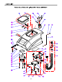
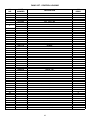
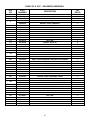
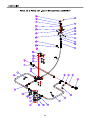
1 VF81405BD GRIP, HANDLE 1
2 VA13477 SCREW, SELF-TAPPING, ST, M4 X 16 3
3 VV13664 WASHER, PLAIN, M4 X M12 X 1 1
4 VF81507 STRAP, PLUG, REAR FILL 1
5 VV13604 SCREW, M8 X 20 6
6 VF13519 WASHER, LOCK, M8 6
7 VF81509 PLUG, EXPANSION 1
8 VF14535 WASHER, PLAIN, M8 X M20 X 2 8
9 VF81406 BUSHING 1
10 VF81404 SUPPORT, RECOVERY TANK 1
11 VF82029A BRACKET, VAC TUBE 1
12 VF82032 SPRING 1
13 VF82030 ADAPTER, TUBE 1
14 VF82031A GASKET, TUBE ADAPTER 1
15 VF82123 DECAL 1
16 VF82070 LABEL, LEFT 1
17 VV13652 NUT, LOCK, M3 2
18 VF82114 BRACKET, CHARGE PLUG 1
19 VF82402 WIRE, #6 X 600 1
20 VF82401 WIRE, #6 X 600 1
21 VF81723 CONNECTOR 2
22 VF13511 WASHER, TOOTH, M3 2
23 VF14244 SCREW, M3 X 20 2
24 VF13495 SCREW, M6 X 16 7
25 VV13607 WASHER, LOCK, M6 9
26 GT13032 WASHER, PLAIN, M6 X M16 X 1.5 7
27 VF81715 STANDOFF 2
28 VF82067 BRACKET 1
29 VF14232 SCREW, M6 X 10 2
30 VF82078 SCREEN, FILL 1
31 VF13543 SCREW, SELF-TAPPING, ST, M4 X 16 2
32 VF13544 SCREW, SELF-TAPPING, ST, M4 X 10 6
33 VA13483 WASHER, PLAIN, M4 X M9 X 0.8 7
34 VF82081 PLUG, FILL SCREEN 1
35 VF82079 COVER, FILL SCREEN 1
36 VF82001A SOLUTION TANK 1
37 VF82071 LABEL, RIGHT 1
BAT105I BATTERY, 105 A/H, 12V 2
BAT130I BATTERY, 130 A/H, 12V 2
39 VF82076 PLATE 1
40 VF82072 SPACER, BATTERY 1
VF81724 CAP, BATTERY, BLACK 2
VF81724R CAP, BATTERY, RED 2
42 VF82403 CABLE, BATTERY 1
43
VF14234
SCREW, M8 X 16 2
44
VF13513
NUT, M8 2
45 VF81408 PLATE, LOCK 2
38
41
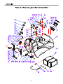
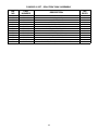
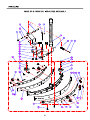
FANG20 & 20T - SOLUTION TANK ASSEMBLY
18

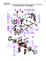
DIA
NO
PART
NUMBER
DESCRIPTION
NO
REQ'D
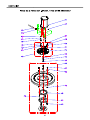
46 VF81416 HOSE BARB 2
47 VF82161 CLAMP (16-25) 1
48 VF82061B TUBING 1
49 VF14230 SCREW, M5 X 15 3
50 VV13601 WASHER, LOCK, M5 3
51 VF13532 WASHER, PLAIN, M5 X M11 X 2 3
52 VF81202 PLATE, SQUEEGEE, LOCK 1
53 VF14235 SCREW, M8 X 35 1
54 VF48216 WASHER, LOCK 1
55 VF82050 HANDLE, SQUEEGEE, LIFT 1
56 VF82050A BUSHING 1
57 VF14248 SCREW, M8 X 100 1
58 VA13516 WASHER, PLAIN, M10 X M30 X 1.5 1
FANG20 & 20T - SOLUTION TANK ASSEMBLY
19

Page is loading ...
Page is loading ...
Page is loading ...
Page is loading ...
Page is loading ...
Page is loading ...
Page is loading ...
Page is loading ...
Page is loading ...
Page is loading ...
Page is loading ...
Page is loading ...
Page is loading ...
-
 1
1
-
 2
2
-
 3
3
-
 4
4
-
 5
5
-
 6
6
-
 7
7
-
 8
8
-
 9
9
-
 10
10
-
 11
11
-
 12
12
-
 13
13
-
 14
14
-
 15
15
-
 16
16
-
 17
17
-
 18
18
-
 19
19
-
 20
20
-
 21
21
-
 22
22
-
 23
23
-
 24
24
-
 25
25
-
 26
26
-
 27
27
-
 28
28
-
 29
29
-
 30
30
-
 31
31
-
 32
32
-
 33
33


Viper FANG 20 Owner's manual
- Category
- Floor Machine
- Type
- Owner's manual
- This manual is also suitable for
Ask a question and I''ll find the answer in the document
Finding information in a document is now easier with AI
Related papers
-
Viper FANG 20T Owner's manual
-
-
-
-
-
-
-
Viper AS530R Use And Maintenance
-
-
Other documents
-
Ice i28BT Operator's & Parts Manual
-
-
 VANMAR VMS22T User manual
-
B-Tech BT7017 User manual
-
 Truvox International Orbis eco User manual
-
 Bright Solutions BSL1610SE Owner's manual
-
Tennant T3 User manual
-
Nobles 608349 User manual
-
 Triple S Cougar 17 Owner's manual
-
Minuteman 988737UMS User manual


